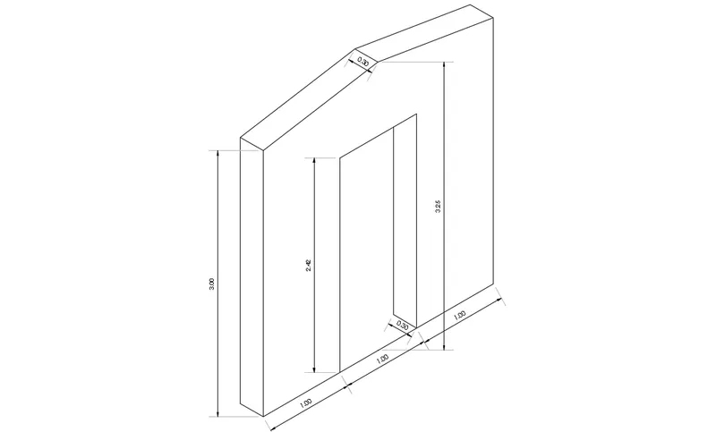
Creating a Floor plan, Footing detail and Isometric view using AutoCad
1) AIM : Create cross section of load bearing wall over spread footing.
Introduction : we design the cross section using autocad.we provide screenshots of footing in it.
Procedure :
- first choose units and limits before creating any figure.
for units, Type command - "UN"
for limits, Type command - "LIM"
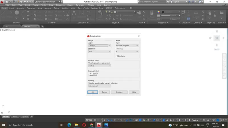
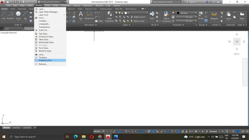
- first selct line and using line create first rectangle for footing with proper dimensions
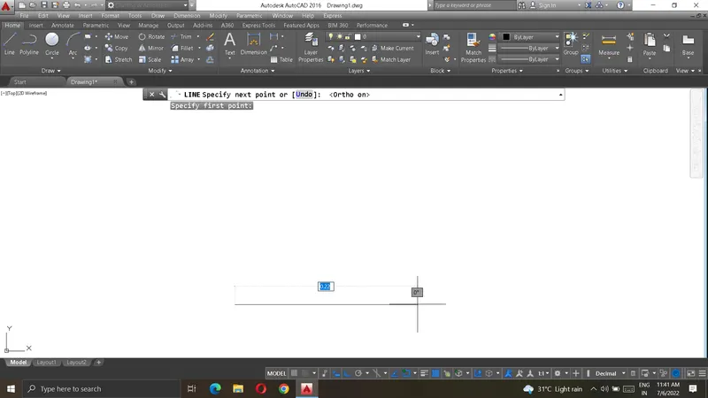
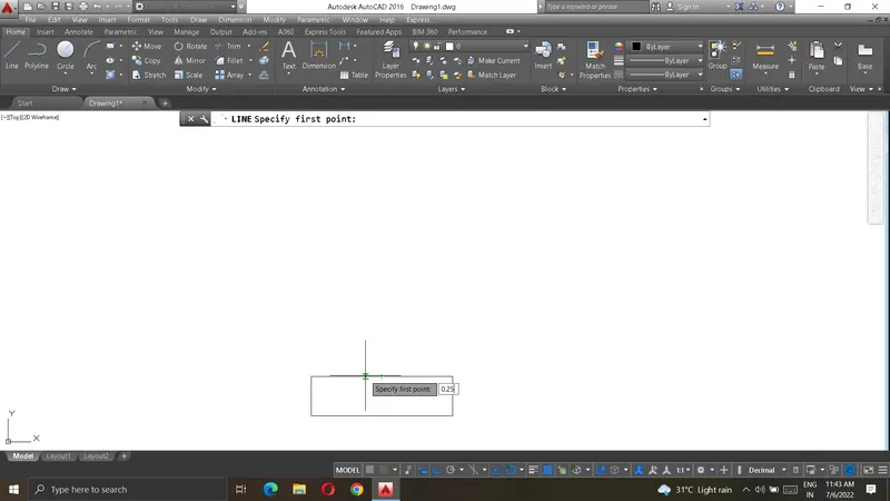
- using line draw tool,trimmodify tool,offset we creating cross section of footing along with wall.
Steps:
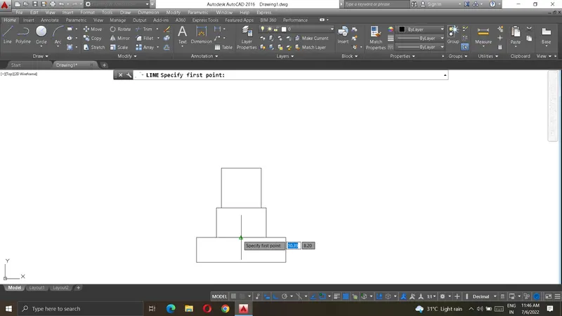
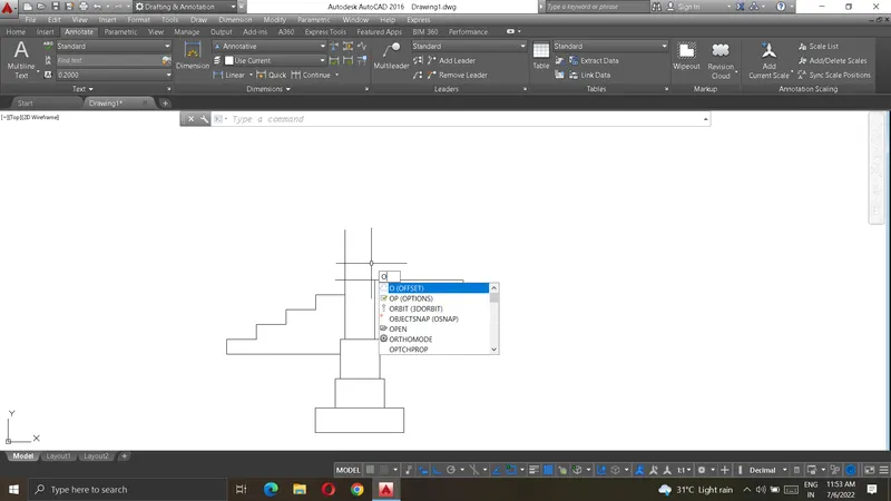
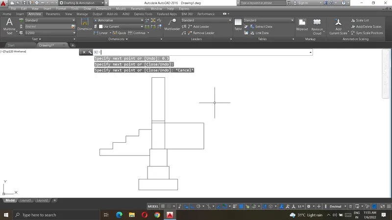
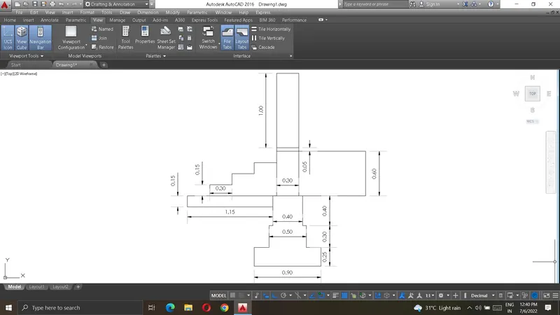
- final result:
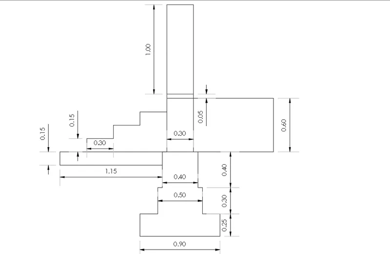
2)
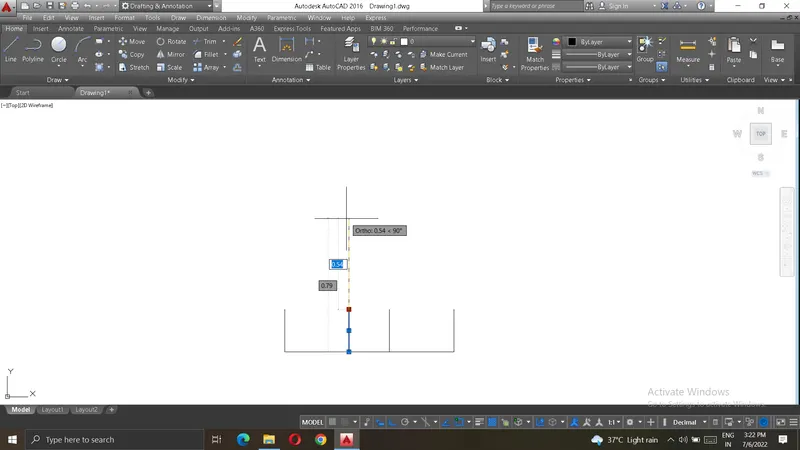
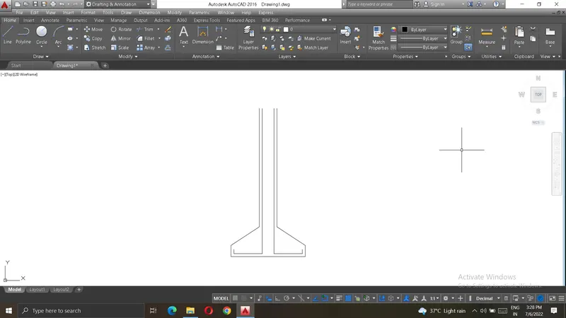
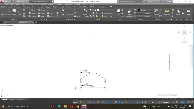
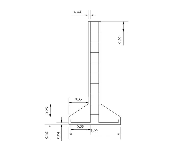
AIM : Create cross section of lsolated footing.
Introduction : we design the cross section using autocad.we provide screenshots of footing in it.
Procedure :
- first choose units and limits before creating any figure.
for units, Type command - "UN"
for limits, Type command - "LIM"
- first selct line and using line create first rectangle for footing with proper dimensions
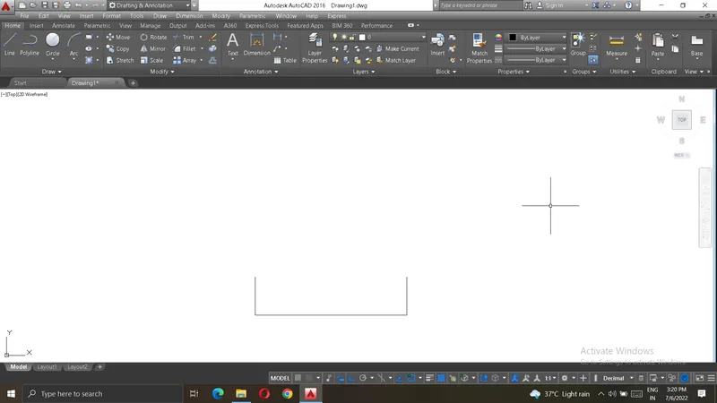
- using line draw tool,trimmodify tool,offset we creating cross section of footing.
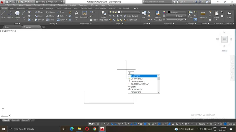
Steps:

- final result:
3)
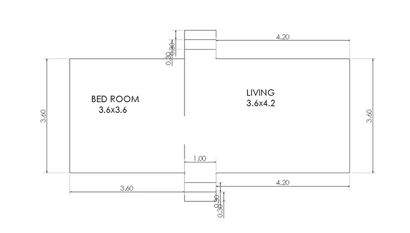
AIM : Create a line diagram of two bedroom building.
Introduction : we create a plan using autocad and we provide screenshots of steps in autocad for better undersanding
Procedure :
- first choose units and limits before creating any figure.
for units, Type command - "UN"
for limits, Type command - "LIM"
- first selct line and using line create first rectangle for footing with proper dimensions
- using line draw tool,trimmodify tool,offset to create a plan of building
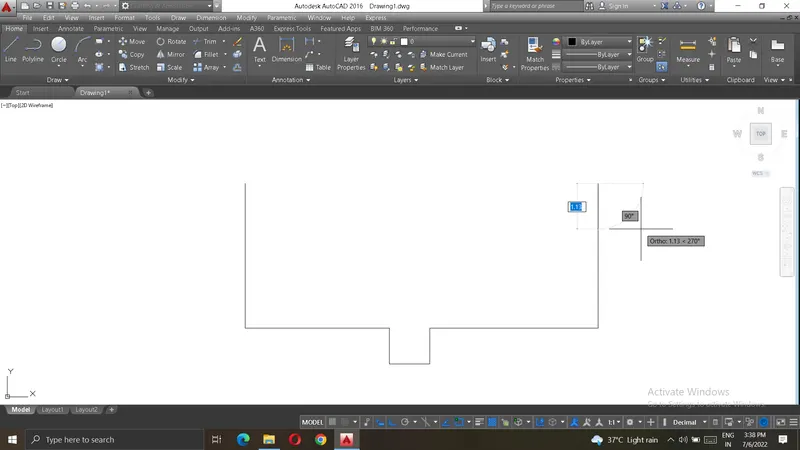
Steps:
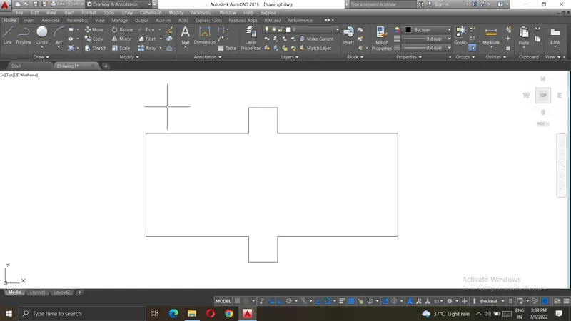
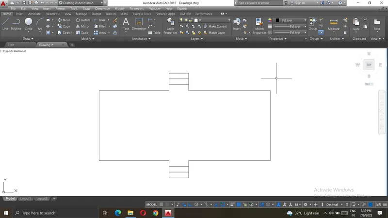
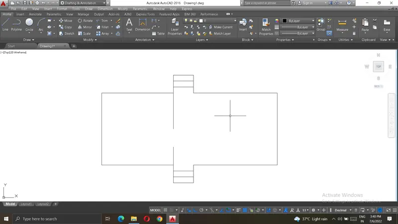
- final result:
4)
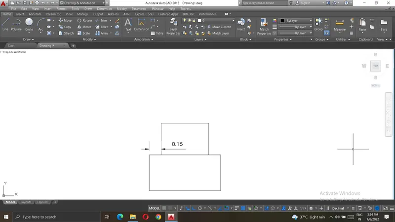
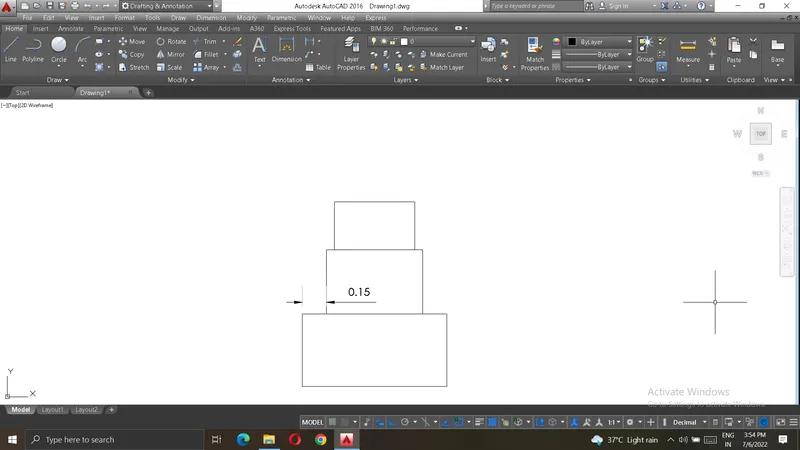
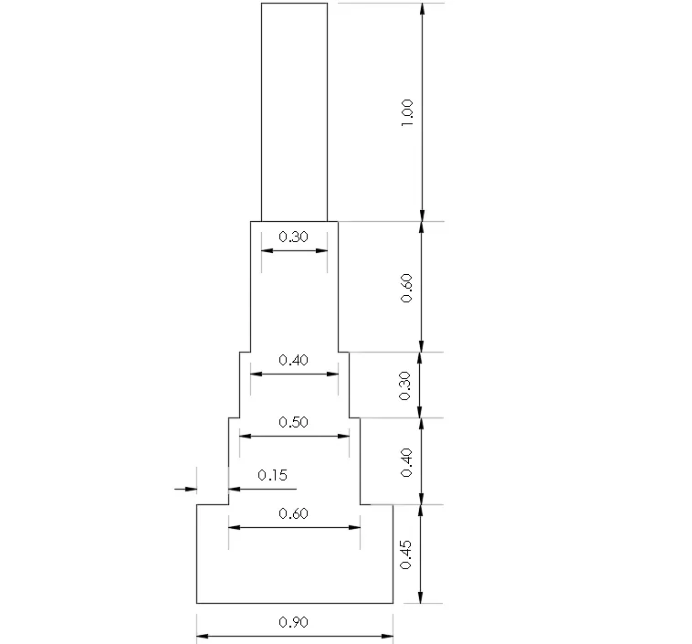
AIM : Create cross section of load bearing wall over footing.
Introduction : we design the cross section using autocad.we provide screenshots of footing in it.
Procedure :
- first choose units and limits before creating any figure.
for units, Type command - "UN"
for limits, Type command - "LIM"
- first selct line and using line create first rectangle for footing with proper dimensions
- using line draw tool,trimmodify tool,offset we creating cross section of footing along with wall.
Steps:
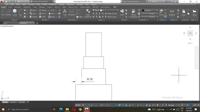
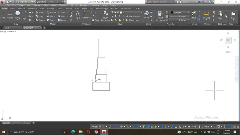
- final result:
5)
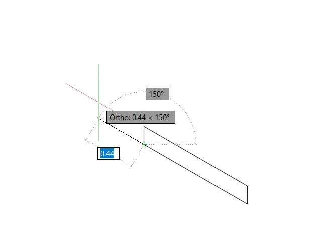
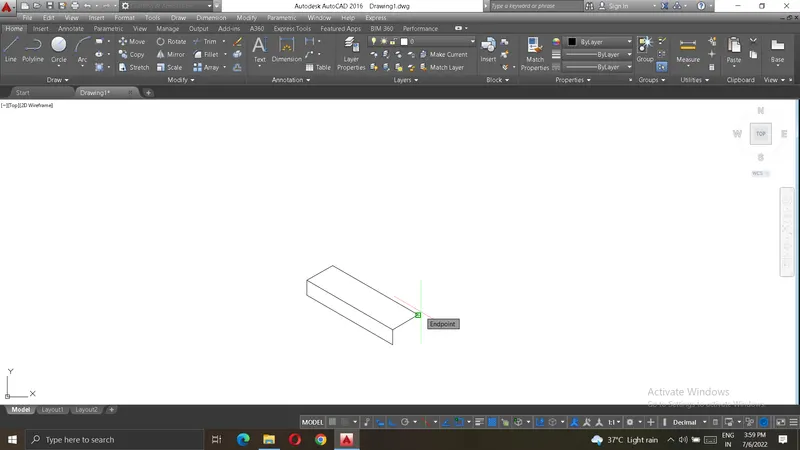
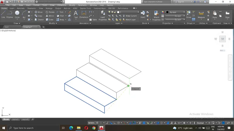
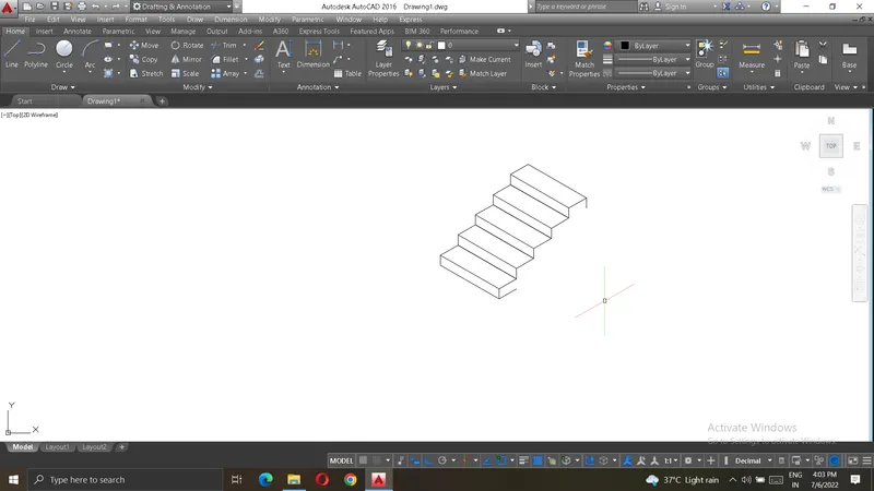
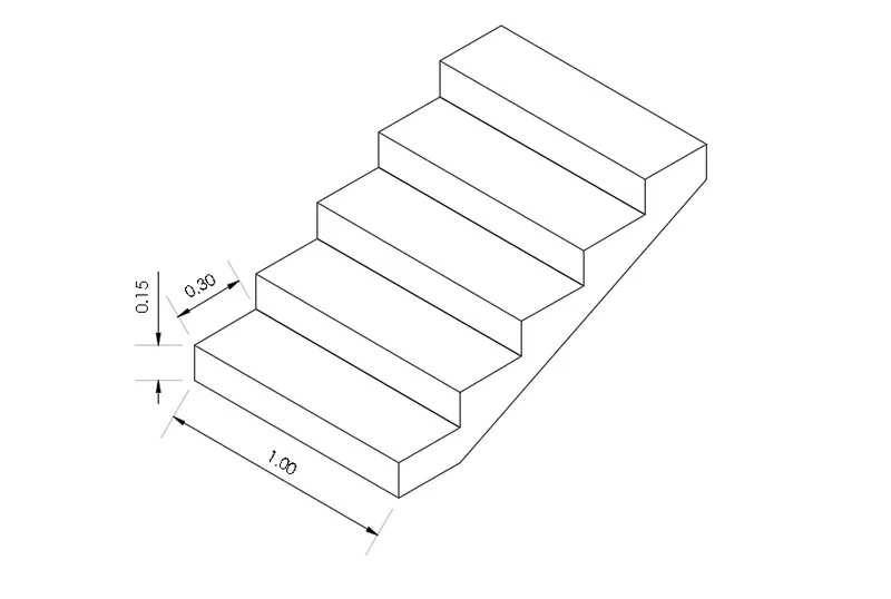
AIM : Create isomatric view of steps
Introduction : create isomatric view of steps using autocad
Procedure :
- first choose units and limits before creating any figure.
for units, Type command - "UN"
for limits, Type command - "LIM"
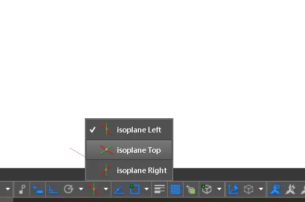
- first isodraft and orthomode on after that choose line and start creating steps.
Steps:
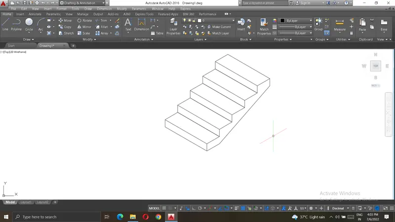
Result:
6)
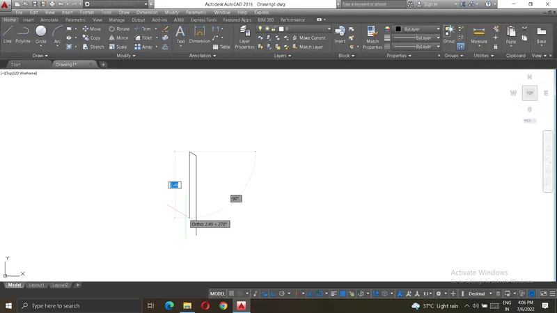
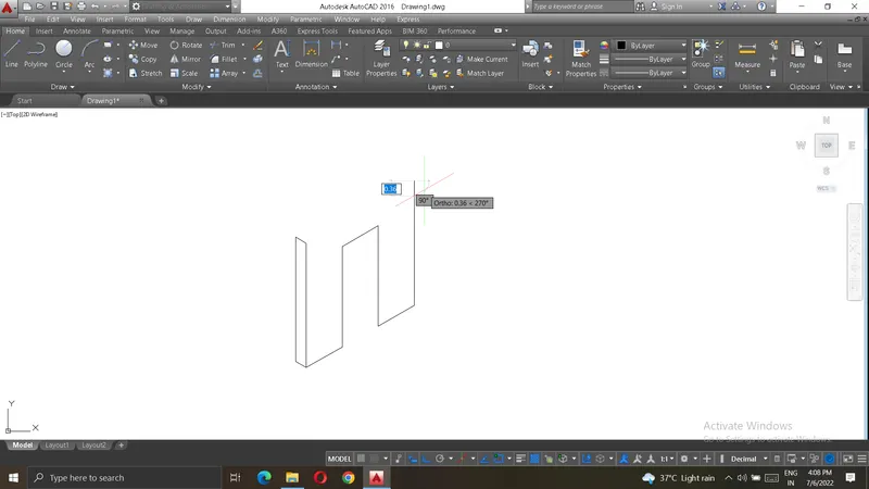
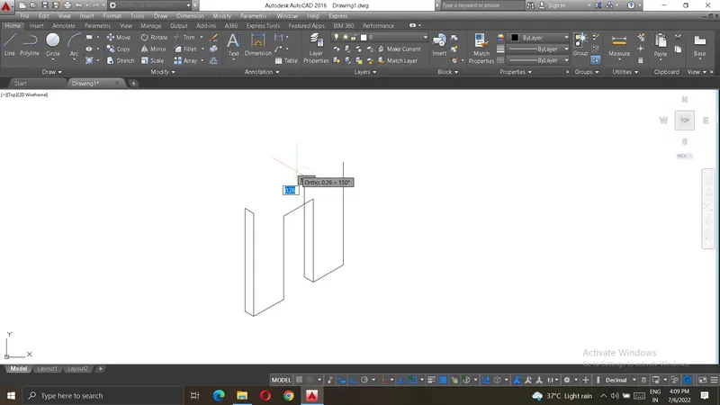
AIM : Create isomatric view of wall with door opening
Introduction : create isomatric view of wall with door opening using autocad
Procedure :
- first choose units and limits before creating any figure.
for units, Type command - "UN"
for limits, Type command - "LIM"
- first isodraft and orthomode on after that choose line and start creating steps.
Steps:
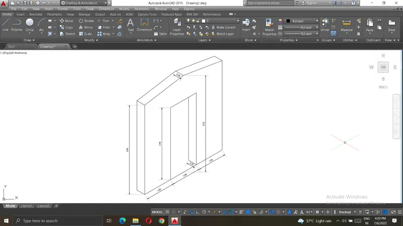
Result: