Week 1 Challenge
1)
1.1) Steps involved to upload a .std file through web mail?
i) Select STAAD Import from the backstage.
ii) The Import from STAAD.Pro dialog opens.
iii) Click on General settings to browse and select a STAAD.Pro (*.std) file to import.
iv) Select Use Mapping File in Section Mapping settings, and then click on browse and select a mapping file to import.
v) Set the catalog type and catalog instance assignments for the imported member types.
vi) This data is used by AECOsim Building Designer to rebuild the members' structural data as defined in the structural member catalogs.
vii) In Steel settings, select a section definition that is to be designated as the Default Section Name.
viii) This section definition is applied to imported members whose section data is not available in AECOsim Building Designer.
ix) Check Verify to scan the imported file for unknown sections.
x) The Unknown Sections dialog appears providing an opportunity to write the unknown sections to the active XML section
definition file before importing.
xi) In Revision Tracking, check Use Design History. Design History tracks changes to a DGN file.
Viewing details about the revision by using the controls on this tool.
xii) Click Import.
xiii) The update design dialogue appears. Review detailed information about each imported member and
select which ones you want to import before accepting them into the target DGN file.
xiv) Click Update to complete the import process.
xv) The structure is updated.
1.2) Name the different materials that can be designed using STAAD Pro.
i) We can Assign different materials to our model
A) AS a Concrete
B) As a Steel member
C) AS a Timber
D) As a Stainless Stell
E) AS a Aluminium
ii) To assign this type of material
iii) Click on Material
iv) Selelct Isotropic material
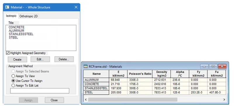
v) Select the material which you have to assign to the model .
vi) Click on Assign to view option or you can select respective members and Click on assign to Selected beams option
1.3) Is it possible to capture images in STAAD Pro? If yes how?
i) Yes it is possible to capture the images in Staad Pro
ii) For that Click on View tab
iii) Click on Camera option
iv) Select the view which you want to take .
1.4 ) Name the three ways by which you can create a model.
i) There are different ways which we can create model .
ii) Open the Staad Software .
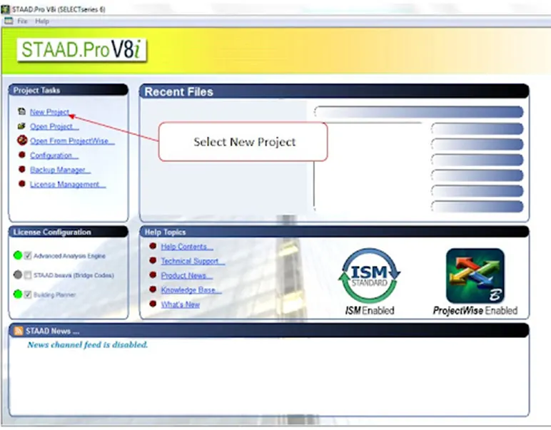
iii) Click on New Project
iv) Once you click on New project a following dialog box will open
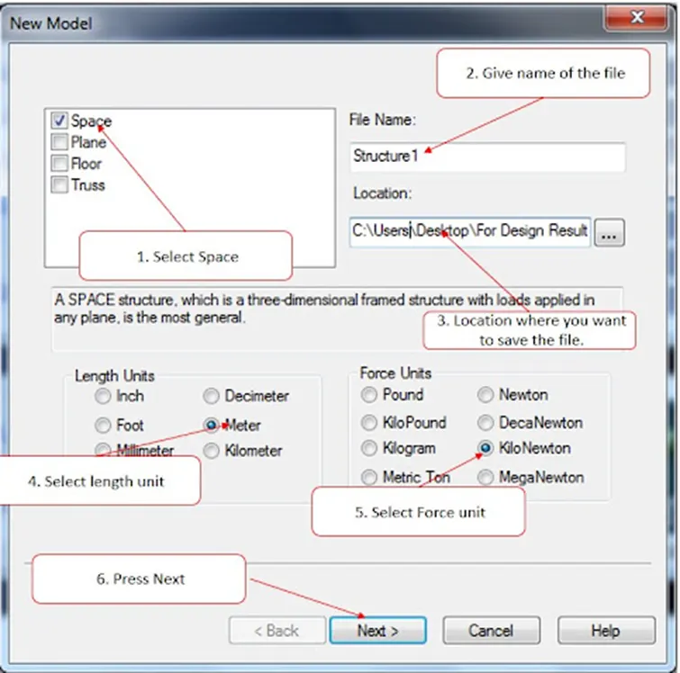
v) Once you select Space , a following dialog box will open
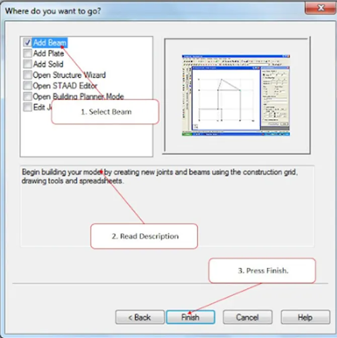
vi) Here you can select Add beam , Add Plates etc
vii) Once you select on that A modal space will open as shown below .
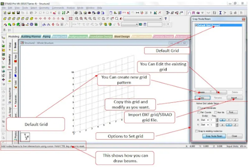
viii) Now Structural Wizard -
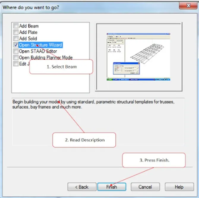
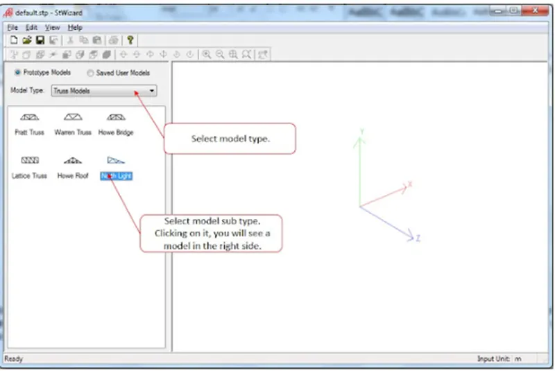
i) Once you clikc on that it will take you to some default model in which you can edit the data
ix) Staad Editor -
i) If you very good with Staad pro or once you have very handy experience with software
ii) You can use this option to create a model
iii) Staad Editor you have to directly enter the input like coding .
1.5) Write the steps followed to assign properties in a model.
i) Once you create a geometry next step is to assign the material properties .
ii) After Defining all the property
iii) Select the Property
iv) Select the respective members and Click on Assign to selected Views .
v) Similarly assign all the property to other members
vi) You can check by using Missing property tool check in any property is missing .
vii) Once all the properties are assign now you can assign material such as concrete , steel , timber etc .
2)
2.1) Name any six design parameter involved in RCC design.
Following are the parameters are required in RCC Design -
1) Clear Cover - It allows you to spcify clear cover to outermost reinforement .
2) CLB and CLT - They are used to provide separate cover at top and bottom reinforcement .
3) Depth - They are used to specify limiting depth .
4) FC - Compressive strength of Concrete - This is an most imp parameters to take into consideration .
5) Fy Main - Yield Strength of steel reinforcement . - This is used to specify the yield strength of steel
6) MAX main and MAX sec = This is used to specify the diameters of bars which you are going to use.
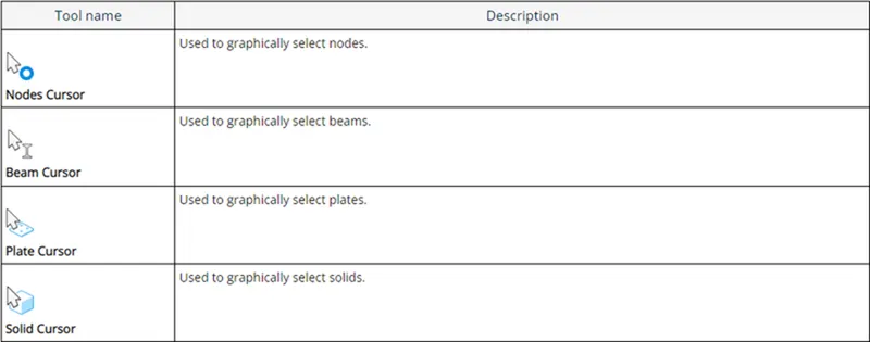
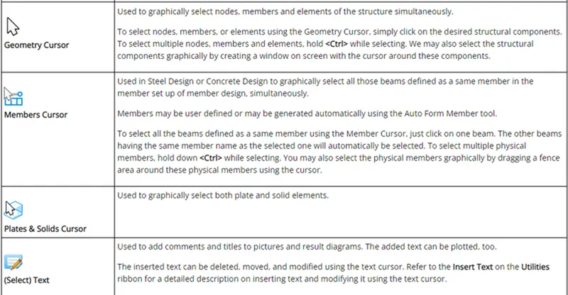
2.2) What are the different cursor types available in STAAD Pro -
2.3) How will you generate different views for a model? State the steps involved.
i) We can create different views as per our convienent
ii) For that Select the view whichever you want
iii) Top View , Front view etc
iv) If you want to select particular element only
v) Select the element whichever you want
vi) Click on View tab
vii) Under View tab - There is an option called as Selected View only
viii) So you can see the selected view only which is helpful in Complex structres .
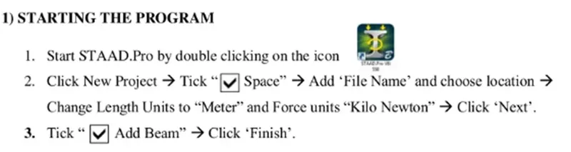
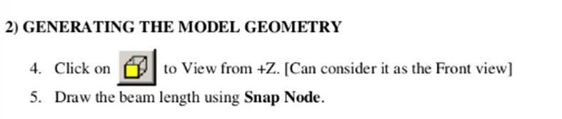
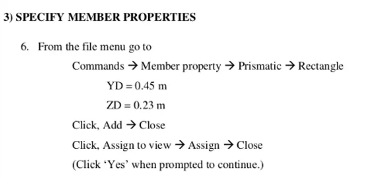
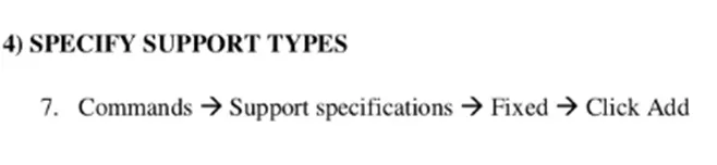
2.4) Explain the procedure to define a “Simply Supported” condition in STAAD Pro -
2.5) Name any five topics that you will include while creating DBR.
i) In DBR we can include following topics
1) Introduction - Which covers scope and structure of this note
2) Structural Layout - It covers brief description about structural framing system adopted for project showing plan and section of
building
3) Loads and Loads Combination - It covers brief description about loads and loads combination considered in design
4) Analysis and Design methodology - It describes the approach for structural analysis and design
5) Quality Annexure plan - It covers the quality control aspects followed in design and preparation of drawings .
2.6) Describe the term “Multi material design” of STAAD Pro.
i) After Analysis structure has to be designed to carry loads acting on it considering a certain Factor of safety
ii) In India structures are designed by using various Indian codes for both concrete and steel structures .
iii) The design in staad pro supports over 70 international codes and over 20U.S codes in 7 languages
iv) After designing the structure it is again analyzed and results of analysis for each beam and column is shown in
output file .
3)
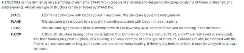
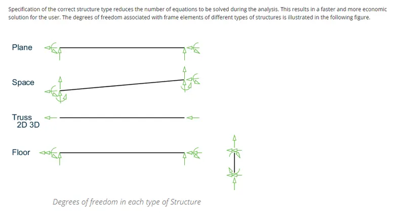
3.1) Name the structure systems in STAAD Pro? Explain each system?
3.2) Explain the coordinate system adopted in STAAD Pro software.
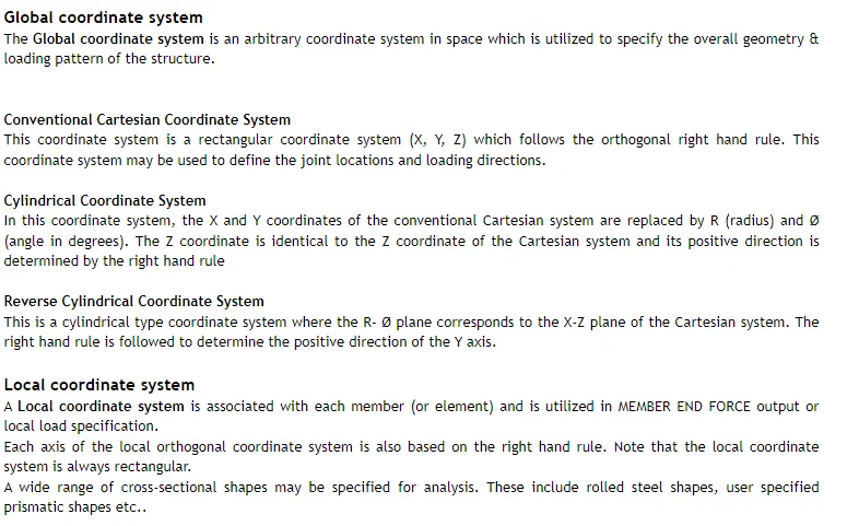
i) Staad Pro uses two types of coordinate system
A) Global Coordinate System -
B) Local Coordinate System -
3.3) Elaborate DBR and its uses -
i) DBR is nothing but Daily Basis Report
ii) To specify the and compile data required for analysis and design of structural elements of the project
iii) It clearly depicts the assumptions and specification that are being used to develop the construction documents for a project
iv) It will also avoid the scop creep that can derail the project schedule and lead to budget overruns
v) It basically transform the WHAT into HOW .
vi) When a particular employee joins the new company in midway of project this DBR will help him in understanding the
project current situation
vii) All the specification and poperties , material etc all the information is akready mentioned in DBR
viii) So he need not have to go to highr authority everytime .
ix) DBR will help him in that situation
3.4) Explain the different types of analysis options in STAAD pro.
1) Perform Analysis -
i) This is a Linear static 1st Order differential analysis
ii) This type of analysis is used for Building of primary loads cases
iii) Perform analysis is used to design every single elements .
2) P - Delta Analysis -
i) This is 2nd Order analysis
ii) In which it governs secondary load cases such as Seismic Analysis
iii) As name suggests it calculate the moment with respect to apply load and calculate deformation under
apply loads
3) Perform Cable Analysis
i) This analysis is used whenever we have cable element in our model
ii) Cable analysis is generally used for Crane loading or incase of Lifting Analysis
4) Non Liner Analysis -
i) This is an type of Static Non linera analysis
ii) This type of ananlysis is not applicable for Solid structures
iii) Non Linera Ananlysis does not considered plastic hing moment developed in structure .
5) Perform Pushover Analysis
i) This type of analysis is used to study the seismic analysis
ii) Under this Analysis Deformation of structure is also studied .
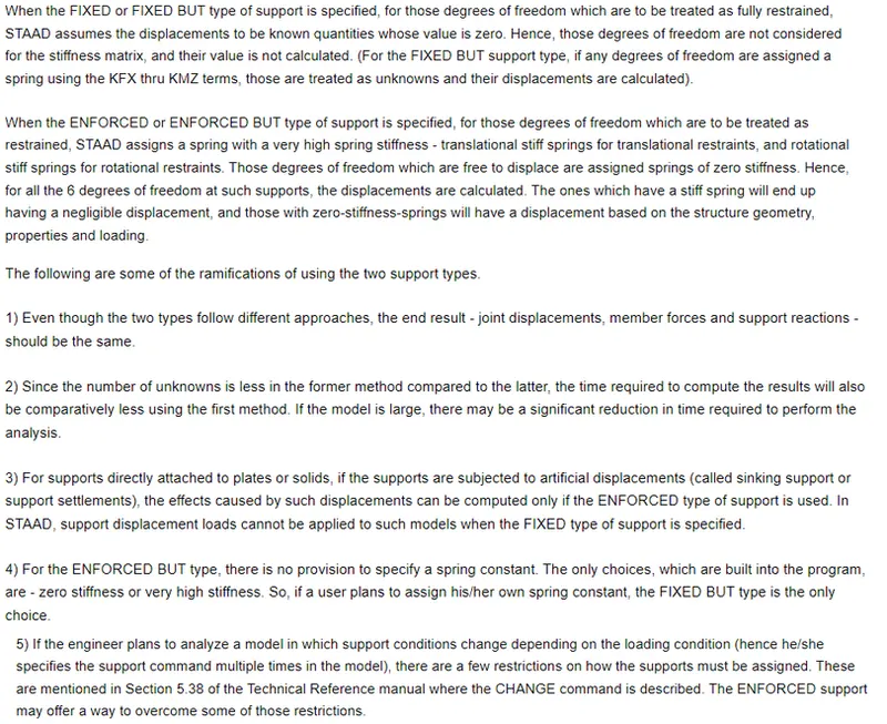
3.5) Explain the difference between Fixed and Fixed But condition
i) Difference between Fixed and Fixed but condition
Practical -
Aim - To create an Staad Model with given section Properties .
Procedure -
Step 1)
i) open the Staad Pro Software
ii) Click on New Project
iii) Click on Add beam .
Step 2)
i) Once you click on Add beam
ii) A Snap beam Node will occure
iii) Where we can draw the beams
Step 3)
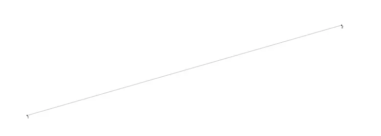
i) Select Node Cursor and draw the 1st node ( 0,0,0)
ii) Command - Cntrl + C and draw the 2nd node at a distance of 16 m ( 16 ,0,0)
Step 4)
i) Now we have to assign the supports
ii) Click on Supports
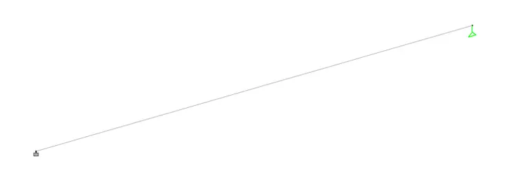
iii) Select Node 1 - Set Support Condition as Fixed
iv) Select Node 2 - Set Support Condition as Roller Support
Step 5)
i) Now we have to assign the material properties
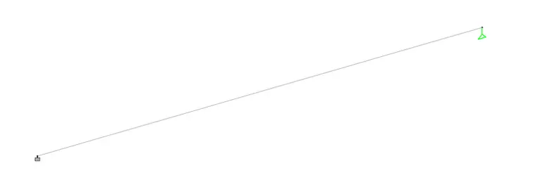
ii) Click on Material - Define - Rectangle - Enter Dimensions beam - ( 230mm x 500mm)
iii) Select the beam and Click on Assign to selected beam
iv) Define the material as concrete .
Step 6)
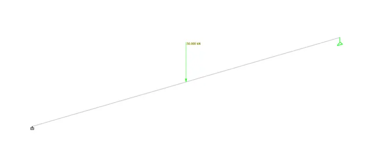
i) Now we have to assign Point load at the center .
ii) Right Click on the screen - Click on Insert Node - Select Midpoint
iii) A node is added to the center
iv) Click in Define load cases
v) Name it as Dead Load
vi) Again Define load Cases
vii) Name it as Live load
viii) Assign self weight under Dead load case
ix) Click on Live load - Select Nodal Load - Enter the vales as (-50) Kn ( GY )
Step 6)
i) Now click on Run Ananlysis
ii) Select Go to Post Processing Mode
iii) Where you can see the Results
iv) Click on Beam stresses
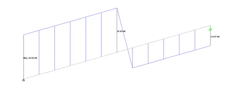
v) Where you can see the Shear Force and Bending moment
A) Shear Force
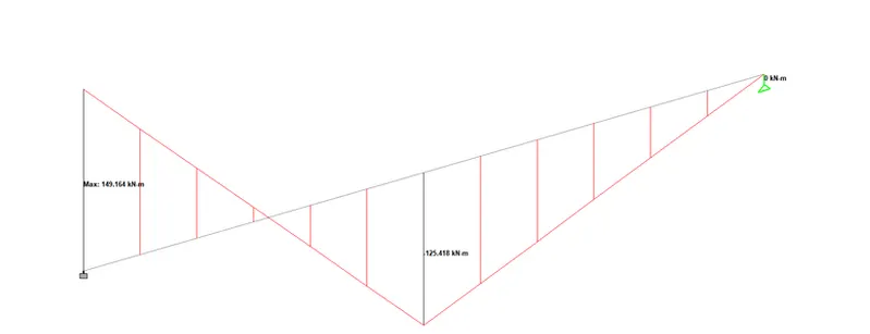
B) Bending moment
Results -
i) A model is created successfully in Staad Pro
ii) Shear Force and Bending moment diagram is obtained with the help of software .