Week 1 Challenge
1.1 – mail > compose > attach the .std file> import the .std file
1.2 – the different material that can be designed in the staad.pro are concrete, steel , stainless steel, and aluminum.
1.3 – yes, take picture command.
1.4 – the three ways you can create a model are analytical, physical and building.
1.5 – go to properties tab> define> rectangular> YD and ZD.
2.1 – the six design parameters are ultimate tensile strength of steel -FU, yield strength of steel – FY, allowable compression- main, max allowable deflection -DFF, max allowable depth DMAX, minimum deflection DMIN.
2.2 – the tree different cursor types available in STAAD.PRO beam cursor, plate cursor, solid cursor, node cursor.
2.3 – goto view tab> select different views.
2.4 – supports> create support> select fixed support> and assign it to the beam member.
2.5 – topics to include while creating DBR are introduction of project, structural plan, loads and loads combinations, material properties and analysis and design specifications.
2.6 – the term “multi material design” refers to that the STAAD.PRO can be used in different materials such as steel, concrete, aluminum, timber, composite structure.
3.1 – the structure system in staad.pro are plane, space, frame, truss.
3.2 - there are two coordinate system in STAAD.PRO they are global coordinate system and local coordinate system. The GLOBAL coordinate system is an arbitrary coordinate system in space which is utilized to specify the overall geometry & loading pattern of the structure. A LOCAL coordinate system is associated with each member (or element) and is utilized in MEMBER END FORCE output or local load specification.
3.3 Before starting any project, a critical and vital element is a well-defined design basis (also called design requirements or basis of design) in addition to a well-defined scope of work (SOW). If not appropriately defined and documented, it results in scope changes, delay in the project timeline, impact on the project budget, and sometimes a total disaster. A concise and complete design basis document makes the basis of a quality design product and a successful project.
3.4 – the different types of analysis options in STAAD.PRO are perform analysis, p delta analysis, pushover analysis, non linear analysis, buckling analysis. Etc.
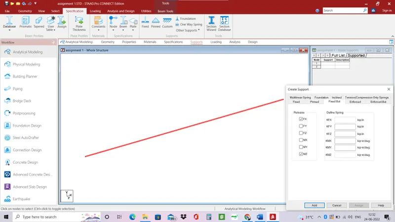
3.5 – in fixed condition all six degrees of freedom is restrained and in fixed but condition we can release some degree of freedom as required.
Practical.
- Open STAAD.PRO software.
- Select analytical and metric system
- Go to geometry tab> grids> beam grids.
- Edit the beam grid to get the required number with respect to 16.
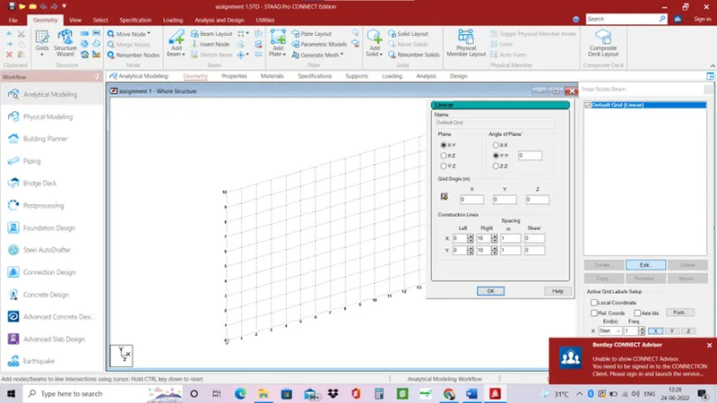
- Draw the beam.
- Now assign the material and size of the beam.
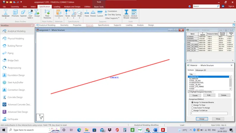
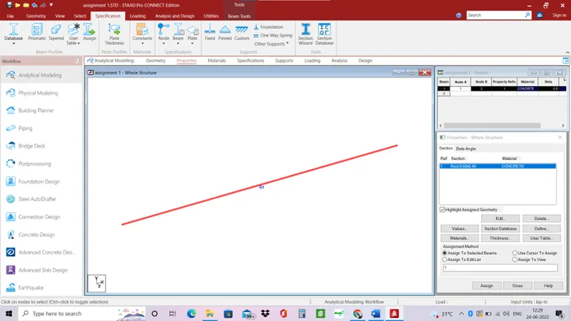
- Add supports to the beam.
- One end fixed and one end roller.
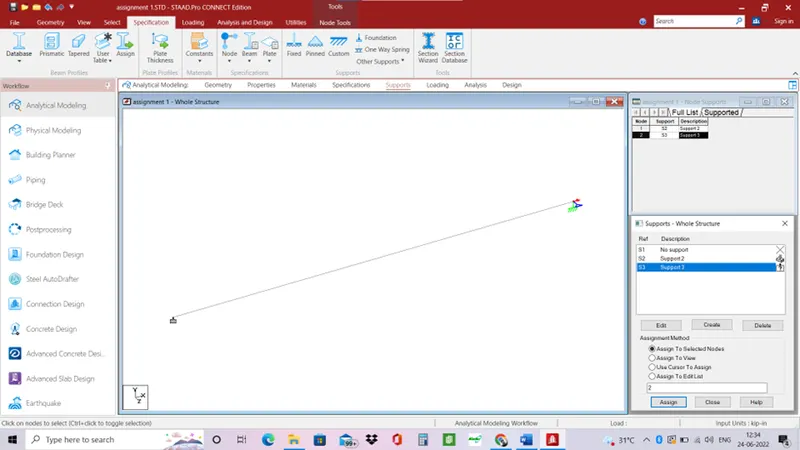
- Now add point load.
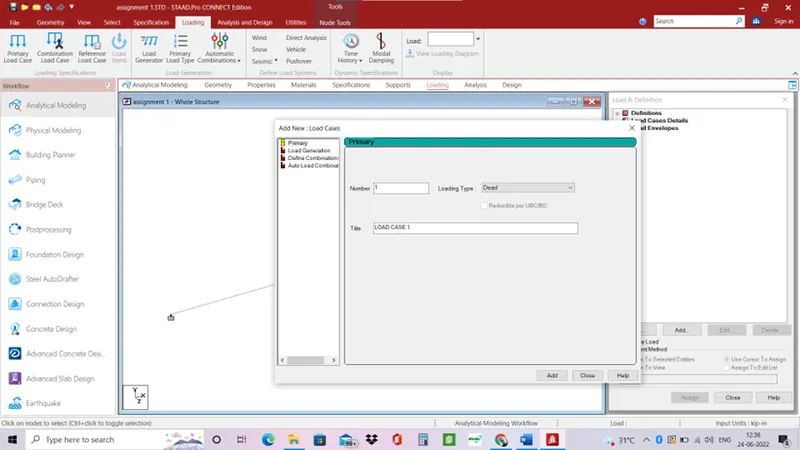
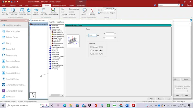
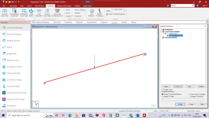
- Run analysis of the model.
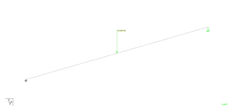
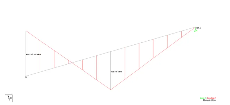
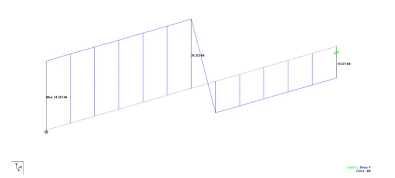
- Shear force diagrams and bending moment diagrams.