Creation of geometries by Coordinate system methods using AutoCad
Aim: -
To Create the geometries from P1 to P2 using all the coordinates system methods. With line and circle tool to create the geometries.
Procedure: -
Geometries P1 and P2 are drawn in all the coordinates system. Rest of the geometries are similar.
For P1
Using relative coordinate system:
- In command bar type ‘line’ or ‘L’ for selecting line tool.
- Specify the first point as 2,1 in the command bar.
- Specify the next command as @6,0 in the command bar.
- Specify the next command as @0,1 the command bar.
- Specify the next command as @-5,1 in the command bar.
- Specify the next command as @0,4 in the command bar.
- Specify the next command as @5,0 in the command bar.
- Specify the next command as @0,1 in the command bar.
- Specify the next command as @-6,0 in the command bar.
- Press ‘C’ in the command bar to close the geometry.
Using relative polar coordinate system:
Here we use angles and distance to the next point.
- In command bar type ‘line’ or ‘L’ for selecting line tool.
- Specify the first point as 2,1 in the command bar.
- Specify the next command as @6<0 in the command bar.
- Specify the next command as @1<90 the command bar.
- Specify the next command as @5<180 in the command bar.
- Specify the next command as @4<90 in the command bar.
- Specify the next command as @5<0 in the command bar.
- Specify the next command as @1<90 in the command bar.
- Specify the next command as @6<180 in the command bar.
- Press ‘C’ in the command bar to close the geometry.
Using direct distance system method:
Direct distance entry enables you to draw an object, such as a line, by pointing in a particular direction with the cursor and entering a distance at the command line.
- Specify the first point as 2,1 in the command bar.
- In command bar type ‘line’ or ‘L’ for selecting line tool.
- Then point the cursor in +x axis and enter distance 6
- Then point the cursor in +y axis and enter distance 1.
- Then point the cursor in - x axis and enter distance 5.
- Then point the cursor in +y axis and enter distance 4.
- Then point the cursor in + x axis and enter distance 5.
- Then point the cursor in +y axis and enter distance 1.
- Then point the cursor in – x axis and enter distance 6.
- Press ‘C’ to close the geometry.
Result: -
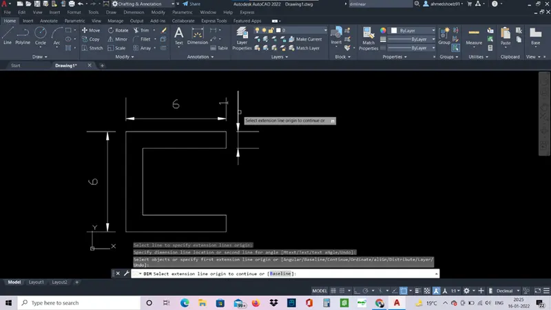
For P2
Using relative coordinate system:
- In command bar type ‘line’ or ‘L’ for selecting line tool.
- Specify the first point as 2,1 in the command bar.
- Specify the next command as @3,0 in the command bar.
- Specify the next command as @0,4 the command bar.
- Specify the next command as @1,0 in the command bar.
- Specify the next command as @0,-4 in the command bar.
- Specify the next command as @3,0 in the command bar.
- Specify the next command as @-2,7 in the command bar.
- Specify the next command as @3,0 in the command bar.
- Press ‘C’ in the command bar to close the geometry.
Using relative polar coordinate system:
Here we use angles and distance to the next point.
- In command bar type ‘line’ or ‘L’ for selecting line tool.
- Specify the first point as 2,1 in the command bar.
- Specify the next command as @3<0 in the command bar.
- Specify the next command as @4<90 the command bar.
- Specify the next command as @1<0 in the command bar.
- Specify the next command as @4<270 in the command bar.
- Specify the next command as @3<0 in the command bar.
- Specify the next command as @7<106 in the command bar.
- Specify the next command as @3<180 in the command bar.
- Press ‘C’ in the command bar to close the geometry.
Using direct distance system method:
Direct distance entry enables you to draw an object, such as a line, by pointing in a particular direction with the cursor and entering a distance at the command line.
- Specify the first point as 2,1 in the command bar.
- In command bar type ‘line’ or ‘L’ for selecting line tool.
- Then point the cursor in +x axis and enter distance 3
- Then point the cursor in +y axis and enter distance 4.
- Then point the cursor in + x axis and enter distance 1.
- Then point the cursor in - y axis and enter distance 4.
- Then point the cursor in + x axis and enter distance 3.
- Then point the cursor in +x axis and enter distance 7.
- Then point the cursor in – x axis and enter distance 3.
- Press ‘C’ to close the geometry.
Result: -
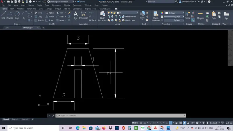
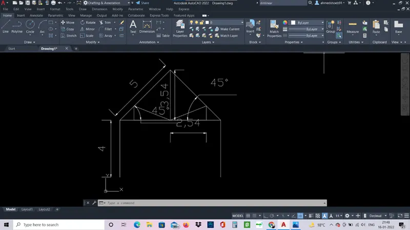
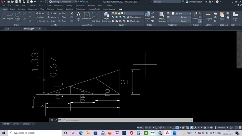
Similarly P4, P5, P7, P8, P9 , P10, profile wood, queen post truss and mono pitch is designed.
P4
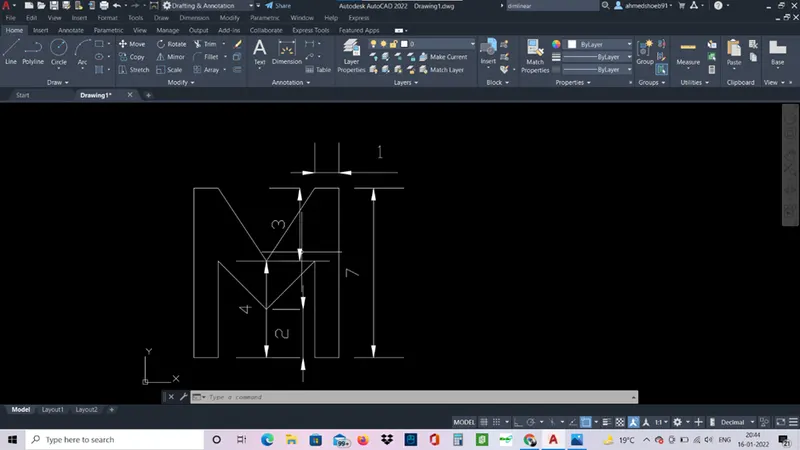
P5
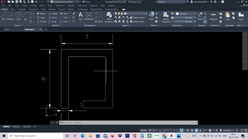
P7
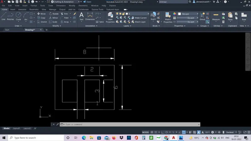
P8
P9
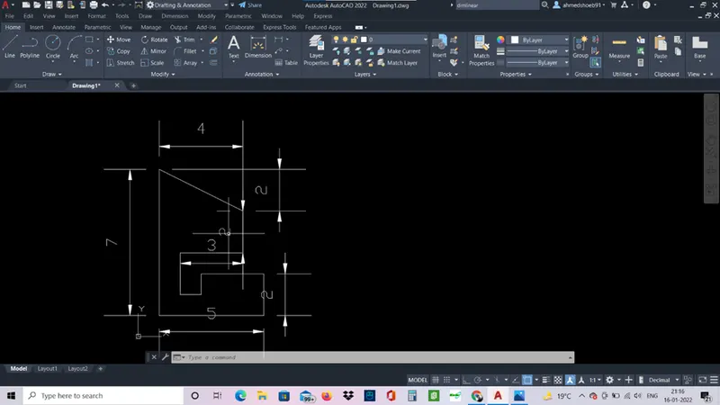
P10
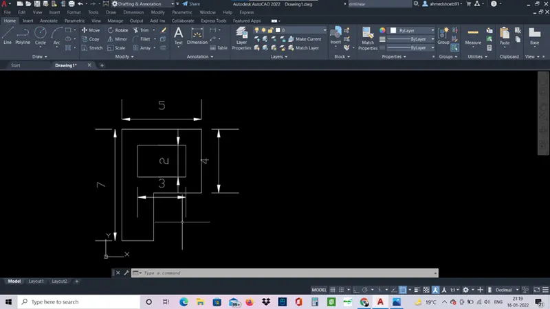
Wood-profile
Here circle command is used,
In command bar type circle and press starting point of circle as 5,4.
A circle will start and enter radius as 2 then a 2 unit radius circle will be drawn.
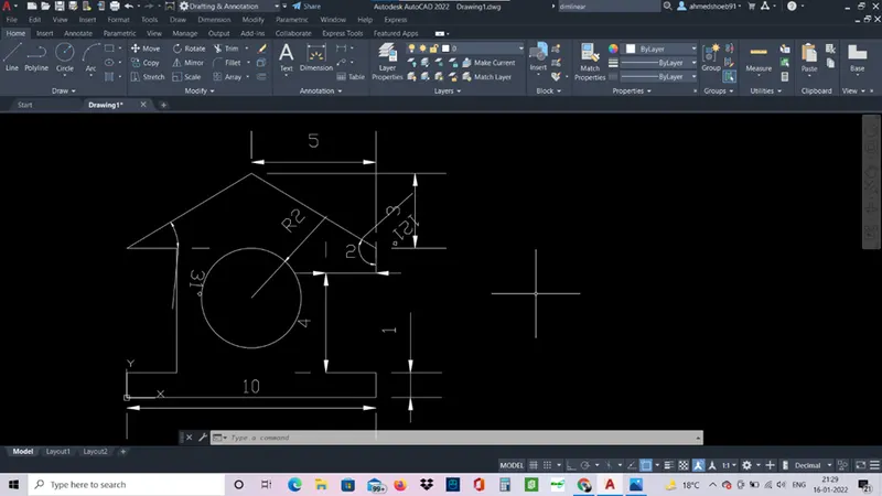
Queen post truss
Mono pitch
Results:
All the given geometries are drawn using line tool and circle tool. And all coordinate system are used to draw the geometries.