Creating a Floor plan, Footing detail and Isometric view using AutoCad
Aim: -
To create a floor plan, footing detail and isometric views using AutoCAD.
Procedure:-
Commands used here are
- Line
- Polyline
- Offset
- Mirror
- Trim
- Isometric snap
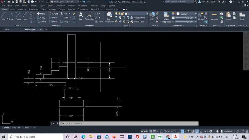
For C1 cross section of load bearing wall
- Enter line command and specify a starting point.
- Using distance relative method plot the line of a distance 0.9.
- Use the midpoint of the line and create a line of 2.7 vertically
- Use the offset command and give the relevant offset both vertically and horizontally.
- Trim the excess lines that are not required.
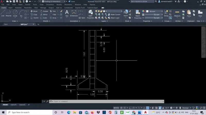
For C2 isolated footing
- Enter line command and specify a starting point.
- Here the geometry is in symmetry so mirror tool can be used.
- Start a line and give a length of 0.5 in horizontally.
- Give the dimensions using offset tool and trim the excess lines.
- After the geometry is finished used the mirror tool and select the base of the footing.
- Mirror the geometry to complete the diagram. In Keep the source object, press yes.
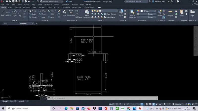
For C3 line diagram of two building
- Use the relative line command to plot the lines.
- For steps use the offset option
- Use the Mtext option to write text.
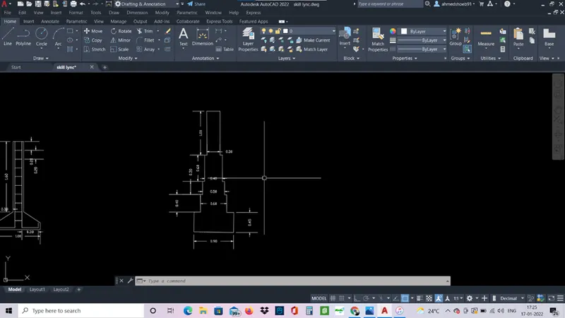
For C4 C.S of load bearing wall
- Here line command is used to start the line.
- Draw the vertical line of 0.9
- Use the offset to give the vertical distance.
- Trim the excess line.
For C5 isometric views of steps.
- Select the isometric drafting on and use the line option.
- Start a line and give a distance of 1 units in left direction.
- See that ortho mode is on ease of use.
- Give the relevant distance of 1 step. You can change the direction of the isometric drafting by F5 key.
- Use the copy tool and select the base of the step and copy as given.
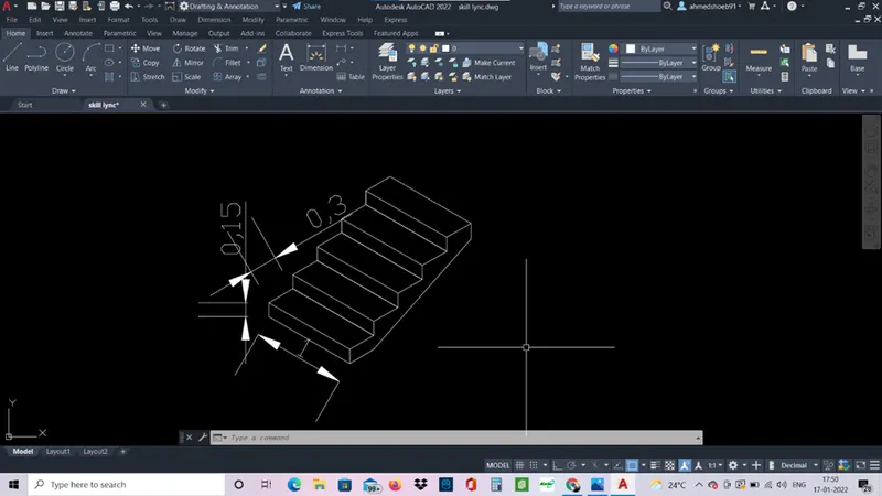
For C6 isometric view of gable wall.
- Same as steps, isometric draft is used to create the gable wall geometry.
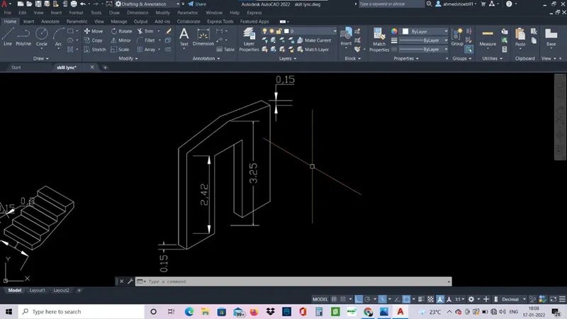
Result:-
Here we use different commands such as offset, mirror, trim, polyline to create 2d geometries. And for 3d view isometric drafting is used.