Drafting of various geometries using Chamfer, Fillet tool in AutoCad
Aim: - to draw given sketches in AutoCAD.
Procedure: -
Tools used: - line, circle, mirror, copy, fillet, trim and rotate.
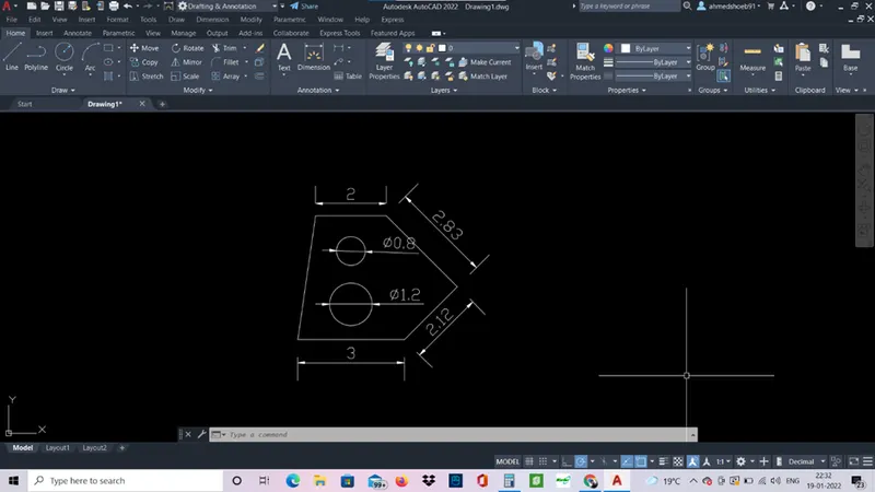
Sketch 1
- Open new file and set units to decimal and precision to 0.00.
- Use command line and draw a line of 3 units horizontally. Then @2.12<45 , @2.83<135. Then 2 units line horizontally. Then press “c” to close the geometry.
- Command offset- select 3m line and give offset of 1m and 2.50m.
- Command circle – at 1m offset draw a circle of dia 1.2 and at 2.5 draw a circle of dia 0.8m.
- Erase the excess lines.
Sketch 2
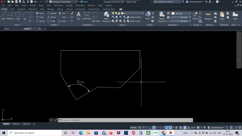
- Units- architectural.
- Command line- select a random point and draw a line of 8’. The at right end @-1.9<270. Use the relative coordinate system for ease. Draw line of 2’10” @225 angle. complete the drawing by using line command.
Sketch 3
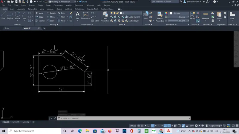
- Units- engineering.
- Command line- 5’ in x direction. 3’3” vertically. 2’6 ½ in x direction. At 5’ line in the right end erect a line of 1’6”. Now close the geometry.
- Command offset- make an offset of 5’ line at 1’6”. And offset of 3’3’’ line at 1’30’’.
- Command circle- make a circle at the intersection of offset line for a dia of 1’6”.
- Erase the excess lines.
Sketch 4
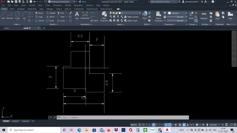
- Units- decimal.
- Command line- select orthomode on and polar tracking on for ease. Start making lines of given dimensions in given directions.
Sketch 5
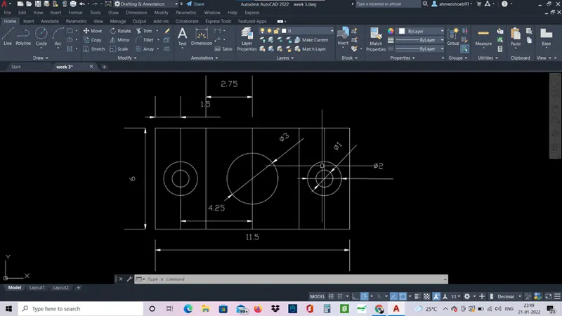
- Units- decimals.
- Command line – make a rectangle of 11.5 x 6 using line command.
- Command offset – select 6m line and make an offset of 1.5 twice on both left and right side. Then make an offset of 2.75 in the middle.
- Command circle- make a circle on the first offset of dia 1 and 2 at midpoint of the line. In the center line make a circle of dia 3 at midpoint.
- Command copy – copy the 1 and 2 dia circle to the point as shown in the sketch.
Sketch 6
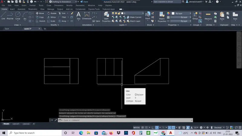
- Units – decimal.
- Command line – make a line of 2 units in horizontal and 1.5 in vertical. Make a rectangle for first figure.
- Command offset – make an offset of 0.5 twice vertically and once horizontally.
- Command trim – trim the excess lines.
- Command line – make a line of 1.5 units in horizontal and 1.5 in vertical. Make a square for second figure.
- Command offset – make an offset of 0.5 twice horizontally and once vertically from the bottom.
- Command trim – trim the excess lines.
- Command line – make a line of 2 units in horizontal and 1.5 in vertical. Make a rectangle for first figure.
- Command offset – make an offset of 0.5 once vertically and once horizontally. Join the offset lines diagonally.
- Command trim – trim the excess lines as shown in the figure.
Sketch 7
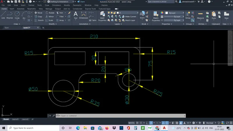
- Units- decimal.
- Command line- draw a line of 210 m in x direction. 75m in -y direction and 100m in -y direction.
- Draw circle with center at 100 and 75m line with radius of 35 and 25 respectively. Make two more circles of dia 50 and 30 at 100m and 75 m line respectively.
- Use the offset tool to give offset of 20m from left and draw a rectangle of 70 x 30m then make a copy of the rectangle at a distance of 30m.
- Use the fillet tool and give the radius of 35,20,6 and 15.
Sketch 8
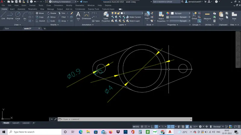
- Units- decimal
- Command circle- draw a concentric circles of dia 5 and 4. Use the line command and draw line of 4.275 from the midpoint of the circle. Draw a circle of dia 0.9 and radius of 0.9.
- Command line- draw a tangent line of 5 dia circle and 0.9 radius circle.
- Mirror – mirror the geometry and trim the excess lines.
Sketch 9
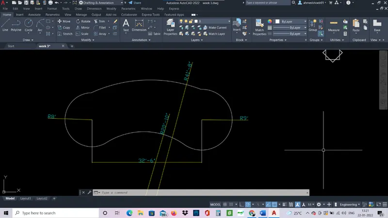
- Units- architectural
- Draw a line of 32’6”. Draw a circle radius 8 and 9 on left and right side of the line.
- Use the fillet tool and give a radius of 41’8’’ at top and 20’10” at the bottom.
- Trim the excess lines.
Sketch 10
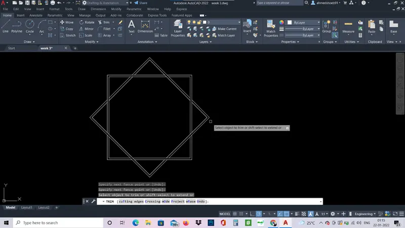
- Units- decimal
- Make a rectangle of dimension 10x 10. Use the offset tool and give a small offset of 0.5 .
- Copy the rectangle and rotate it to 45 degrees. Move the rotated rectangle in the centre.
- Trim the geometry as required.
Sketch 11
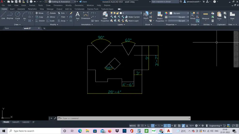
- Units- architectural.
- Command line- make a line of 3’ and move the cursor according to the the geometry and make lines of 4’6”, 4’6” 1’2”,5’, 1’2”, 4’6”, 4’6”,3’, 9’, 20’4”, 9’ to close the geometry.
- Use the offset tool and make an offset of 2’8” and 3’7” of the top line.
- Make an angle of 90 degrees and 60 degrees respectively.
- Draw a square of 3’ in the center and rotate it 45 degrees.
- Trim the excess lines.
Results: -
The given sketches are drawn in AutoCAD using different tools accurately.