Week 1 Challenge
1)
AIM:
To find out the most efficient truss in carrying gravity loads among truss A and truss B
EXPLANATION:
- So the given trusses are observed to be pratt truss and howe truss respectively
PRATT TRUSS:
- In this type of truss, the diagonal members are arranged such that they are in tension and there is an effective use of material. That is they are designed to resist tensile forces only. Whereas the vertical members are in compression and are designed on such a way that they resist buckling
- Typical pratt truss with its compression and tension members and also zero force members are shown in below figure
HOWE TRUSS:
- These type of trusses are completely opposite to that of pratt truss. If we observe the pratt truss upside down we will visaualize the pratt truss as howe truss.
- Here the position of the diagonal members switched as compared to geometry and the diagonal members here are in compression and the vertical members are in tension.
- Typical howe truss with its compression , tension and zero force members are shown in below figure.
- So when the application of gravity loads is concerned, as buckling occurs in compression members and that being the diagonal members in howe truss it effects the truss negatively. Inorder to prevent that we need to thicken the diagonal members which inturn impacts the economy of the truss. This problem is not seen in case of pratt truss.
- Also the number of zero force members are more in pratt truss which inturn helps in increasing its stability over howe truss.
RESULT:
- So here the truss A i.e pratt truss is most efficient when the gravity loads are applied when compared to that of the truss B i.e howe truss.
2)
AIM:
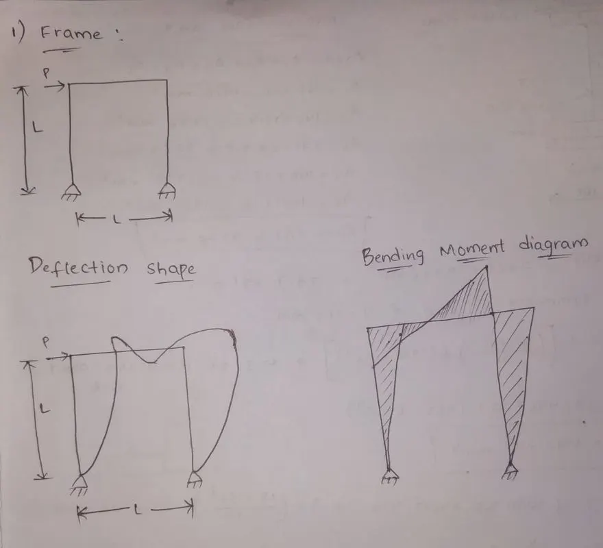
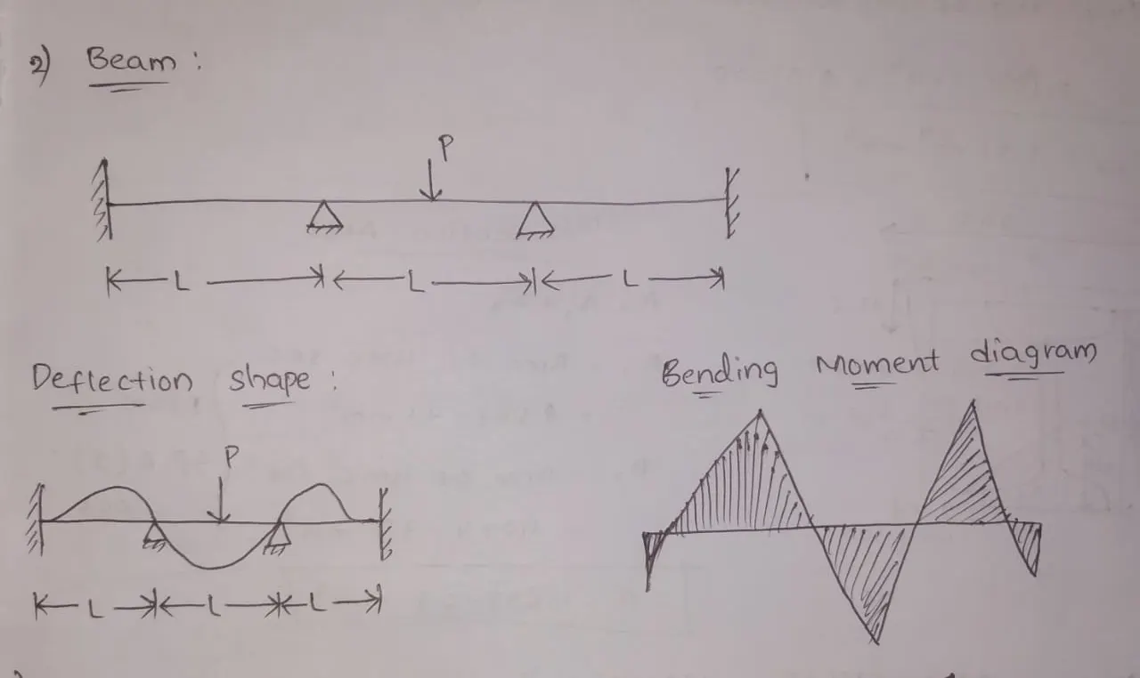
To draw the deflection shape & Bending Moment Drawing under given load conditions for the beams and frames shown below.
Deflection shape & Bending Moment Drawing :
1. FRAME 1:
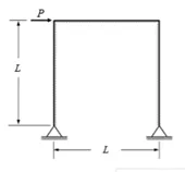
Deflection shape & Bending Moment Drawing:
2. BEAM 1:
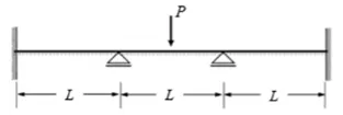
Deflection shape & Bending Moment Drawing:
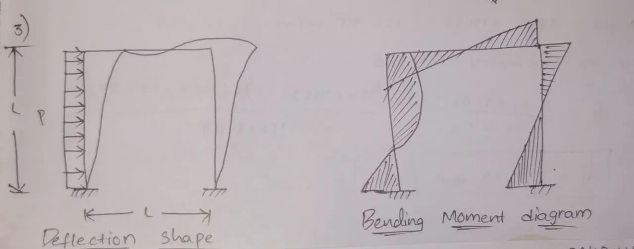
3. FRAME 2:
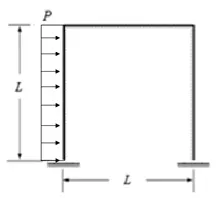
Deflection shape & Bending Moment Drawing:
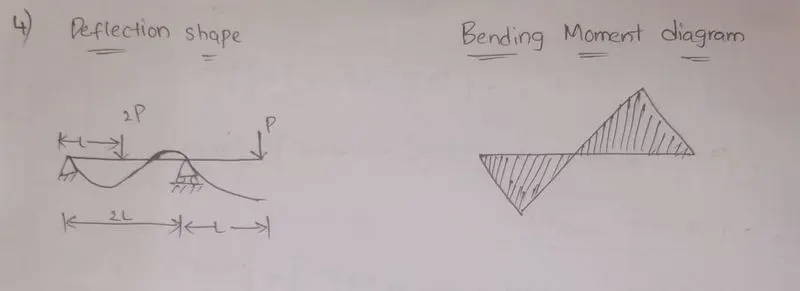
4. BEAM 2:
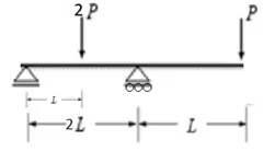
Deflection shape & Bending Moment Drawing:
RESULT:
Deflection shape & Bending Moment Drawings for various beams and frames are drawn above through qualitative approach.
3)
AIM:
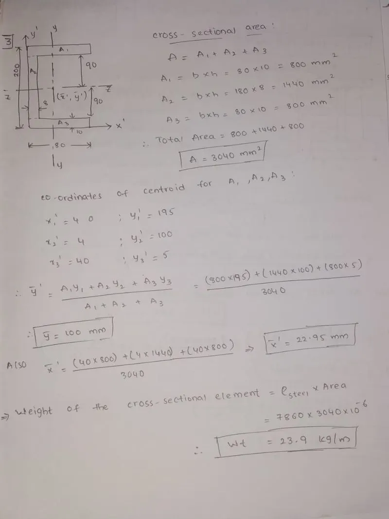
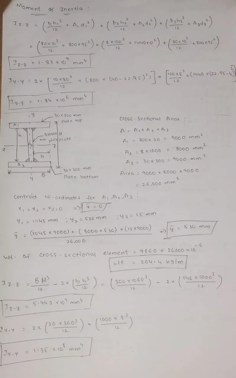
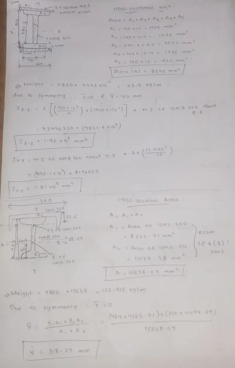
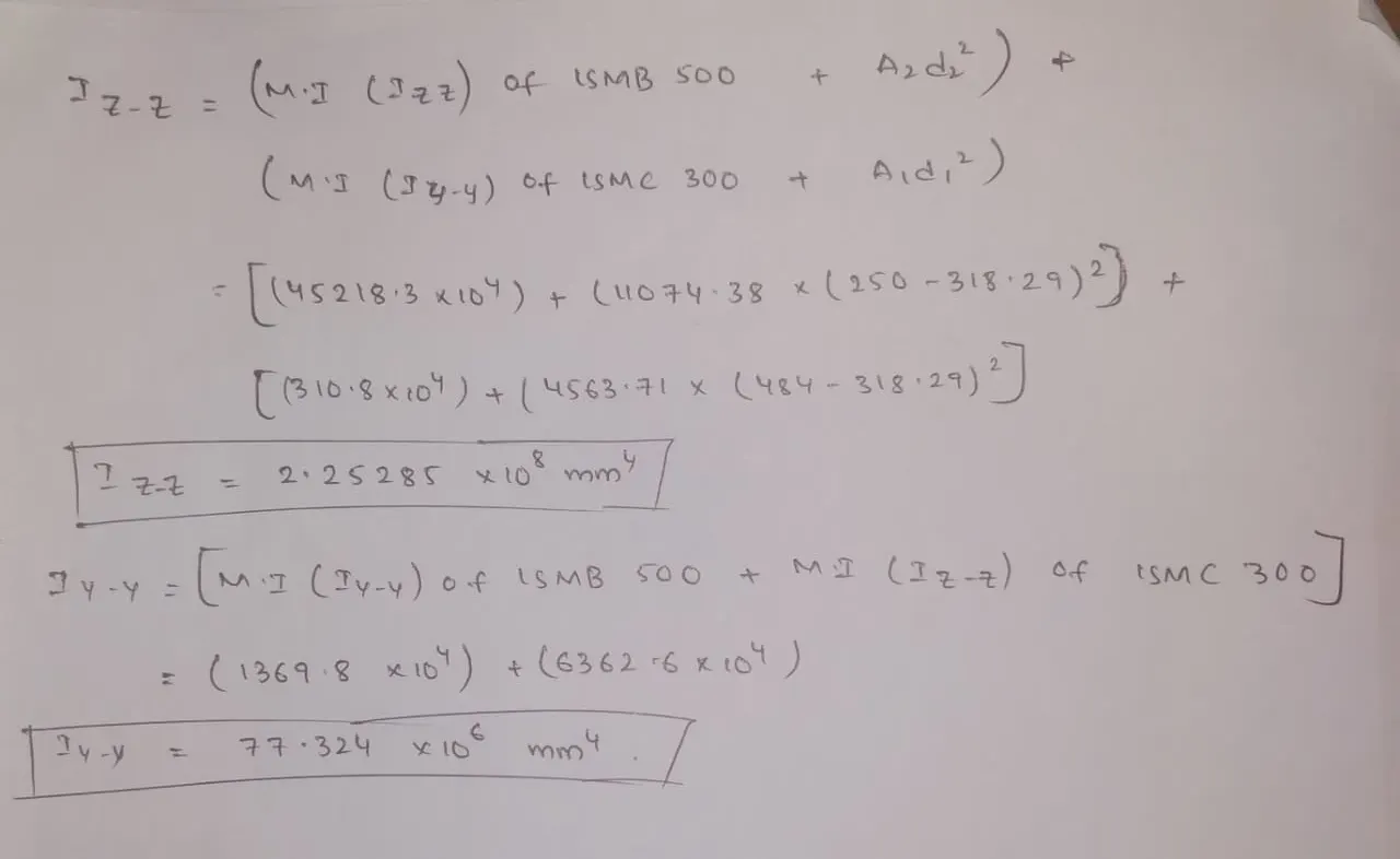
To determine moment of inertia, weight and cross sectional area of the sections
PROCEDURE:
RESULT:
The moment of inertia , weight and cross section area of the sections has been determined succesfully
FIG 1:
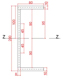
Moment of Inertia ( IZ ) = 1.834133 * 10^7 mm^4
Moment of Inertia ( IY ) = 1.843244 * 10^6 mm^4
Cross sectional area = 3040 mm^2
Weight = 23.8944 kg/m
FIG 2:
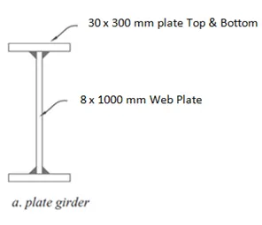
Moment of Inertia ( IZ ) = 5.442 * 10^9 mm^4
Moment of Inertia ( IY ) = 1.35043 * 10^8 mm^4
Cross sectional area = 26000 mm^2
Weight = 204.36 kg/m
FIG 3:
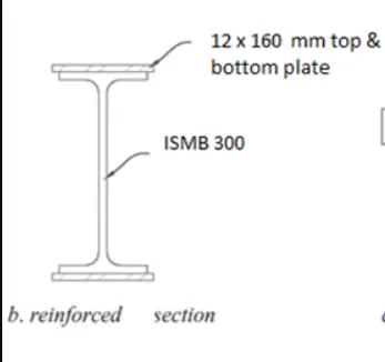
Moment of Inertia ( IZ ) = 1.91712 * 10^8 mm^4
Moment of Inertia ( IY ) = 1.8093 * 10^7 mm^4
Cross sectional area = 9376 mm^2
Weight = 73.695 kg/m
FIG 4:
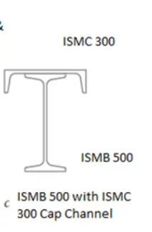
Moment of Inertia ( IZ ) = 2.25285 * 10^8 mm^4
Moment of Inertia ( IY ) = 77.324 * 10^6 mm^4
Cross sectional area = 15638.09 mm^2
Weight = 122.915 kg/m
4)
AIM:
To calculate the load on interior beam, Exterior beam, Interior Girder and exterior girder having Floor Load of 10kN/m2 for the floor framing below.
PROCEDURE:
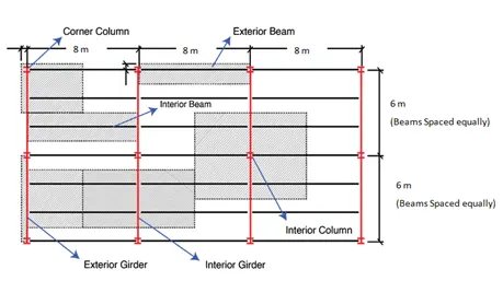
We know that, tributary width = ( distance to adjacent beam to the right / 2) + ( distance to the adjacent beam to the left / 2)
Whereas tributary area = tributary width x span of the beam
Therefore we have,
Load on Interior beam = 10 x 2 x 8 = 160 KN
Load on Exterior beam = 10 x 1 x 8 = 80 KN
Load on Interior Girder = 10 x 4 x 8 = 320 KN
Load on Exterior Girder = 10 x 4 x 4 = 160 KN
RESULT:
Hence, the load on interior beam, Exterior beam, Interior Girder and exterior girder are calculated as shown above
5)
AIM:
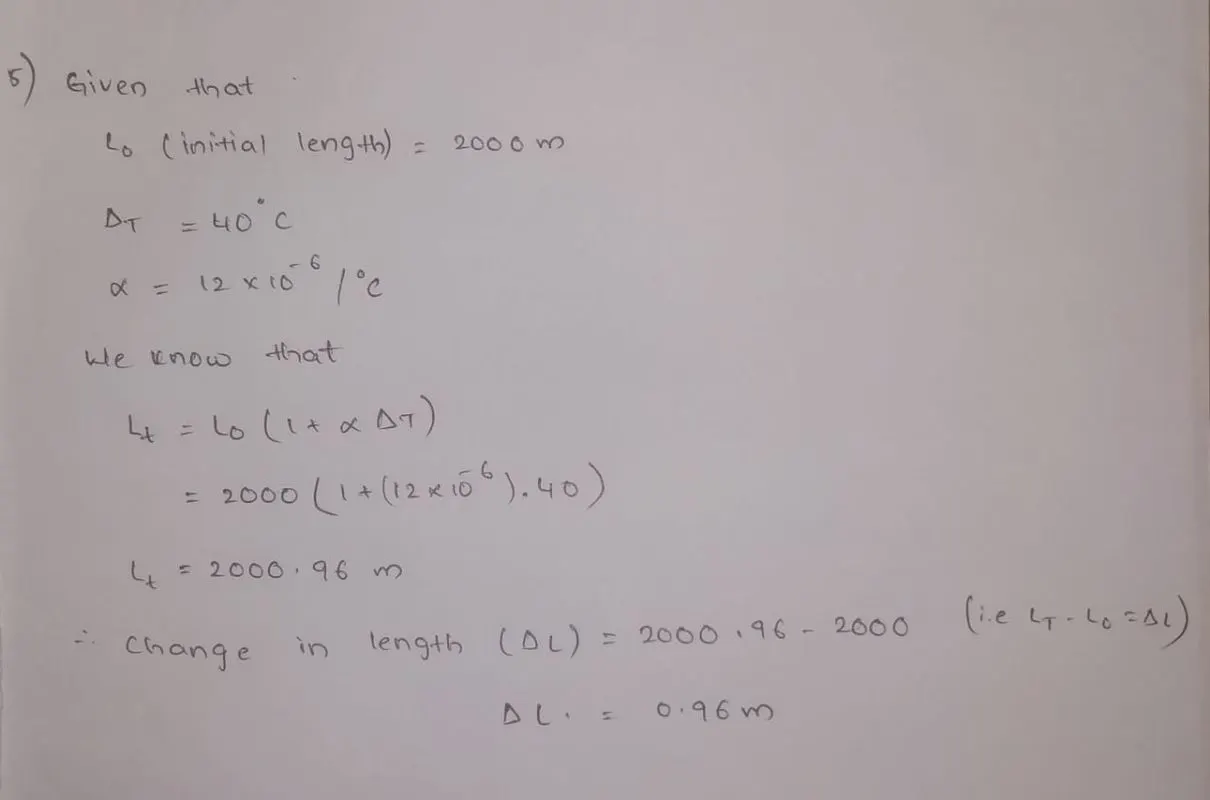
To calculate the length difference and the total length due to temperature difference.
PROCEDURE:
RESULT:
Initial length = 2000 m
Final length = 2000.96 m
Length difference = 0.96 m