Week 1 Challenge
Solution.1)
Aim: To find out the most efficient truss out of the given two, to carry the gravity loads.
Explanation:
- If we observe the given types of trusses, we find that the Truss A is "Pratt Truss" and Truss B is "Howe Truss".
- Pratt Truss - In Pratt Truss, the diagonal members are arranged so that they only develop tensile forces. As Such, they can be designed to resist tension only. The vertical members in a Pratt Truss develop compression forces, this means they will typically be more robust and capable of resisting buckling.
- The tension and compression members are in shown in below figure.
Fig.1. Pratt Truss, members in compression, tension and zero force members are shown
- Howe Truss - Howe Trusses are opposite of Pratt Trusses in terms on geometry. If we observe the Pratt truss, upside down we will visualize the Pratt truss as Howe Truss. The switch in position of the diagonal members has very important structural effect as now the diagonal members are in compression and vertical members are in tension.
Fig.2. Howe Truss, members in compression, tension and zero force members are shown
- This lead to one problem that may occur on applying gravity loads. This problem is buckling of Diagonal members in compression. To prevent the buckling of Diagonal members, thicker diagonal elements has to be used which effects the cost, but it does not happen in case of Pratt Truss.
- Also, the number of zero force members are more in Pratt Truss, it is more efficient than Howe Truss to carry the gravity loads.
Result: Hence, we can say that Truss A (Pratt Truss) is more efficient than Truss B (Howe Truss) to carry gravity loads.
Solution.2:
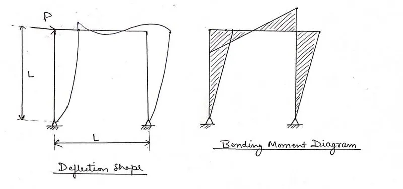
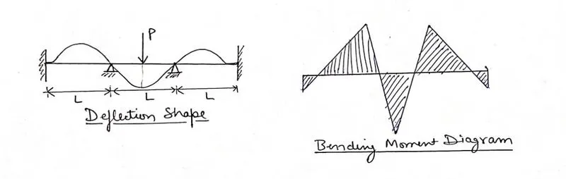
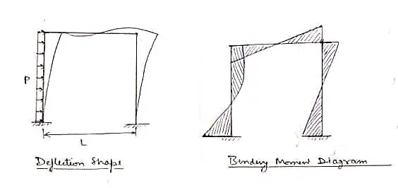
Aim: To draw the deflection of given frame and beams under given loading conditions.
Bending Moment and Deflection Shape:
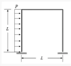
1. Given Frame:
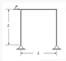
Deflection Shape and Bending Moment Diagram
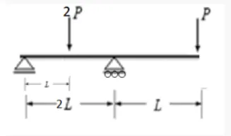
2. Given Beam:
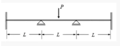
Deflection shape and Bending Moment Diagram:
3. Given Frame:
Deflection shape and Bending Moment Diagram:
4. Given Beam:
Deflection shape and Bending Moment diagram:
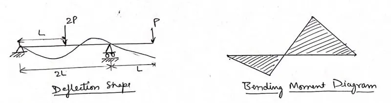
Result: Deflection shape and Bending Moment Diagram for given frames and beams under various loading conditions are drawn.
Solution.3)
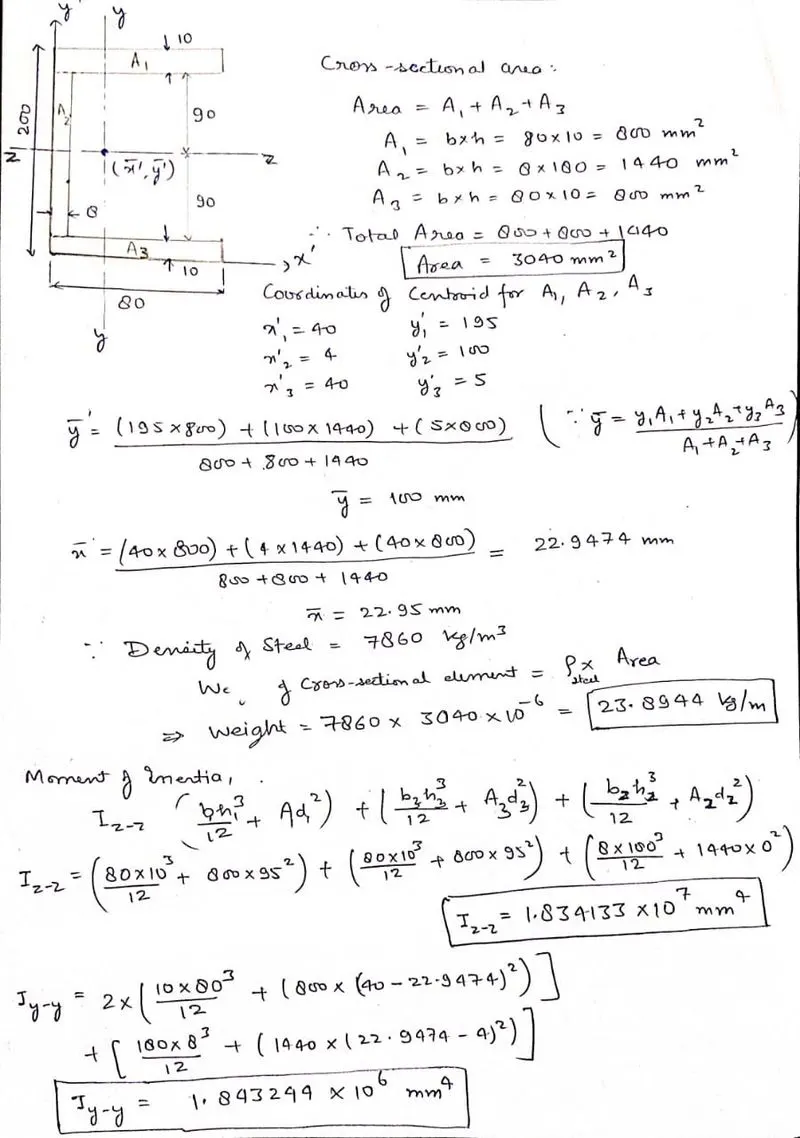
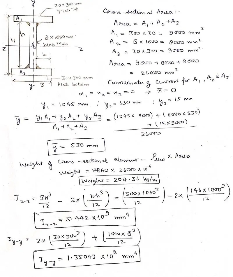
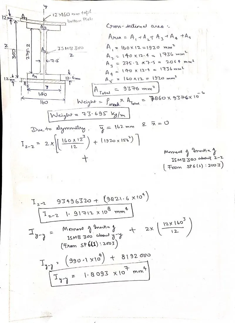
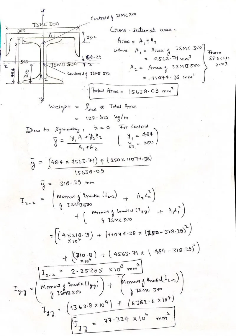
Aim: To determine the Moment of Inertia, Weight and Cross-Sectional area of section.
Procedure: Below is the calculation of Moment of Inertia, Cross section Area and Weight of the section.
Result: Moment of Inertia, Cross Section Area and Weight of the Section has been obtained succesfully
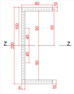
Moment of Inertia (Iz) = 1.834133 * 10^7 mm^4
Moment of Inertia (Iy) = 1.843244 * 10^6 mm^4
Cross Sectional Area = 3040 mm^2
Weight = 23.8944 kg/m
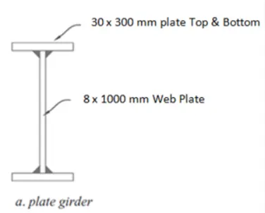
Moment of Inertia (Iz) = 5.442 * 10^9 mm^4
Moment of Inertia (Iy) = 1.35043 * 10^8 mm^4
Cross Sectional Area = 26000 mm^2
Weight = 204.36 kg/m
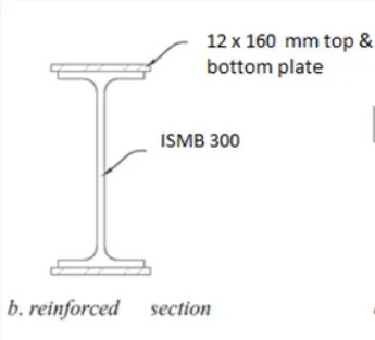
Moment of Inertia (Iz) = 1.91712 * 10^8 mm^4
Moment of Inertia (Iy) = 1.8093 * 10^7 mm^4
Cross Sectional Area = 9376 mm^2
Weight = 73.695 kg/m
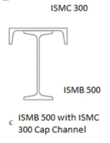
Moment of Inertia (Iz) = 2.25285 * 10^8 mm^4
Moment of Inertia (Iy) = 77.324 * 10^6 mm^4
Cross Sectional Area = 15638.09 mm^2
Weight = 122.915 kg/m
Solution:4)
Aim: To Calculate the load on Interior beam, Exterior beam, Interior Girder and Exterior Girder having Floor Load of 10kN/m^2.
Procedure:
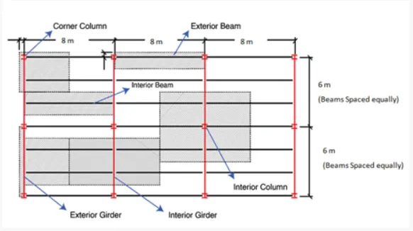
Since, we know that Tributary Width = (Distance to adjacent beam on right)/2 + (Distance to Adjacent beam on left)/2
Tributory Area = Tributary Width x Span of Beam
Hence,
For Interior Beam = 2 x 8 x 10 = 160 kN
For Exterior Beam = 1 x 8 x 10 = 80 kN
For Interior Girder = 4 x 8 x 10 = 320 kN
For Exterior Girder = 4 x 4 x 10 = 160 kN
Result: Hence the load on the Interior Beam, Exterior Beam, Interior Girder and Exterior Girder are calculated as above.
Solution. 5 )
Aim: To Calculate the difference in length and total length due to Temperature Difference.
Procedure:
Given that, Initial Length = 2000 m ; `Delta`T = 40 degree C ; `alpha`= 12 x `10^-6` per degree C
Since, we know that `Lt = Lo(1+alpha.deltaT)`
Putting the values in the above equatio
We get, `Lt = 2000(1+12*10^-6*40)`
Hence, Final Length = 2000.96 m
Change in Length = 0.96 m
Result: Change in Length = 0.96 m and Final Length = 2000.96 m