Vehicle Dynamics - Springs & Anti-roll Bar Selection for a 4WD Sedan Car
AIM: To Select springs and anti-roll bars, and set up swing arm geometry to meet targets for ride frequency, roll gradient and pitch gradient, for a 4WD Sedan car.
OBJECTIVES: Deliver the following-
1. Spring rates (front and rear)
2. Roll bar diameters (front and rear)
3. Rear ride frequency and flat ride plot (at 65 mph)
4. Anti characteristics (front and rear - in terms of percentages and instant center locations)
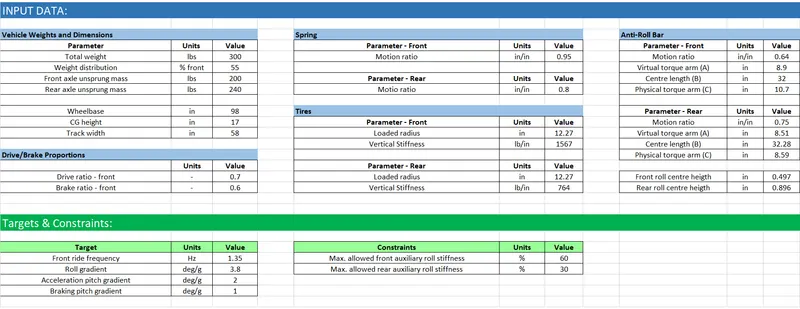
GIVEN DATA:
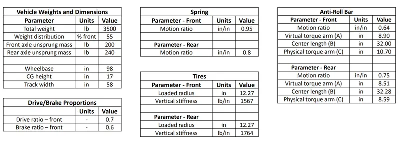
Targets & Constraints-
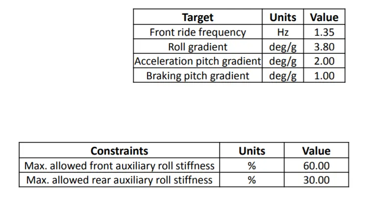
SOLUTION:
1. Ride Analysis:
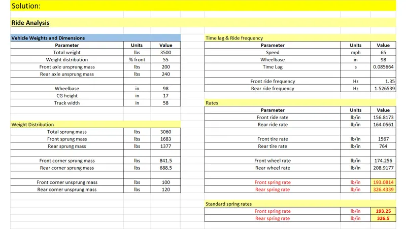
i) From the given weight distribution percentage, the corner weights were calculated.
ii) Vehicle speed was taken as 65mph, and the time lag betweeen the front and rear bump was calculated. Time lag was calculated using the formula shown below,
`t_l = (speed)/(wheelbase) = V/(WB)`
iii) The front ride frequency was set to the target value and the rear frequency was calculated using the time lag.
`f_(r_r) = 1/(1/(f_(r_f)) - t_l)`
where,
`f_(r_f) ->` Front ride frequency (Hz)
`f_(r_r) ->` Rear ride frequency (Hz)
iv) All the rates were calculated using the following formulae-
(Tire rates of both front and rear wheels are given.)
Ride rate,
`k_r = 4pi^2*f_r^2*m_s*(0.454/175.127)`
where,
`m_s ->` corner sprung mass (lbs)
and the additional ratio is the conversion factor for converting N/m to lb/in when the mass is in lbs.
Wheel rate,
`k_w = (k_t*k_r)/(k_t-k_r)`
where,
`k_t ->` Tire rate (lb/in)
Spring rate,
`k_s = k_w/(MR^2)`
where,
`MR ->` Motion Ratio (in/in)
v) The final spring rates were rounded up to the standard values. (standard values are in the increaments of 0.25)
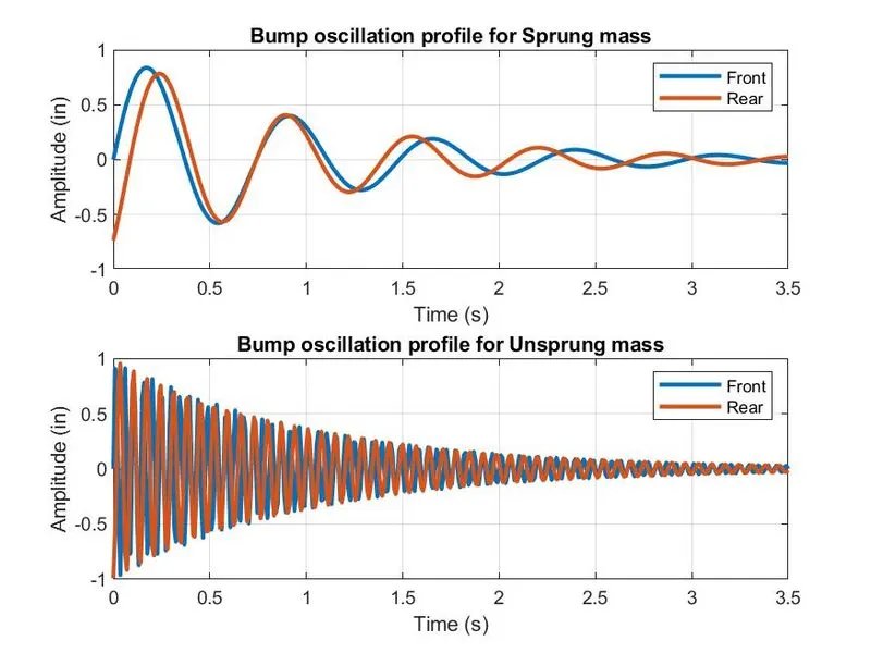
vi) Bump Oscillation Profile
A MATLAB script was used to plot the bump oscillaton profile for the given system.
MATLAB code:
clear all
close all
clc

%weights in lbs per corner
Ws_front = 841.5;
Ws_rear = 688.5;
Wu_front = 100;
Wu_rear = 120;

WB = 98;  %wheel base in inches
V = 65;   %speed of vheicle in mph

%motion ratios
MR_f = 0.95;
MR_r = 0.8;

%time lag in sec
tl = (WB)/(V*17.6);

%recommended natural frequencies at half load
fs_front = 1.35;
fs_rear = 1/((1/fs_front)-tl);

%rates in lb/in
%tire rates
kt_front = 1567;
kt_rear = 764;
%ride rates
kr_front = (((fs_front*2*pi)^2)*(Ws_front*0.453592))/175.126835;
kr_rear = (((fs_rear*2*pi)^2)*(Ws_rear*0.453592))/175.126835;

%wheel rates
kw_front = (kt_front*kr_front)/(kt_front-kr_front);
kw_rear = (kt_rear*kr_rear)/(kt_rear-kr_rear);

%spring rates
ks_front = kw_front/(MR_f)^2;
ks_rear = kw_rear/(MR_r)^2;

%unsprung mass frequencies
fu_front = (1/(2*pi))*((kw_front+kt_front)*1000/Wu_front)^0.5;
fu_rear = (1/(2*pi))*((kw_rear+kt_rear)*1000/Wu_rear)^0.5;

%plotting the graphs
%time range in sec
time = linspace(0,3.5,400);

i = 1;
for t = linspace(0,3.5,400)
    As_front(i) = exp(-t)*sin(2*pi*fs_front*t);
    As_rear(i) = exp(-t)*sin(2*pi*fs_rear*(t-tl));
    Au_front(i) = exp(-t)*sin(2*pi*fu_front*t);
    Au_rear(i) = exp(-t)*sin(2*pi*fu_rear*(t-tl));
    i=i+1;
end

figure(1)
subplot(2,1,1)
plot(time,As_front,'linewidth',2)
hold on
plot(time,As_rear,'linewidth',2)
title('Bump oscillation profile for Sprung mass')
xlabel('Time (s)')
ylabel('Amplitude (in)')
legend('Front','Rear')
grid on

subplot(2,1,2)
plot(time,Au_front,'linewidth',2)
hold on
plot(time,Au_rear,'linewidth',2)
title('Bump oscillation profile for Unsprung mass')
xlabel('Time (s)')
ylabel('Amplitude (in)')
legend('Front','Rear')
grid on

saveas(1,'bump_profile','jpeg')
Plot:
2. Roll Analysis:
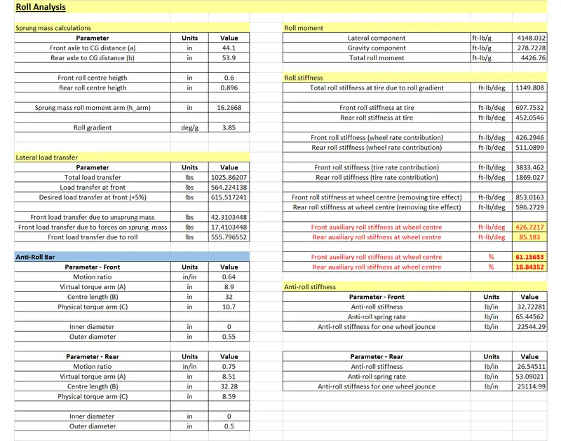
i) The CG distance from front and rear is calculated using the weight distribution.
Front axle to CG distance,
`a = (m_(s_r)* WB)/m`
Rear axle to CG distance,
`b = (m_(s_f)*WB)/m`
where,
`WB ->` wheelbase (in)
`m ->` Total sprung mass (lbs)
`m_(s_f) ->` Front sprung mass (lbs)
`m_(s_r) ->` Rear sprung mass (lbs)
ii) Sprung mass roll moment arm length,
`h_(arm) = h - (Z_(RC_f)*b + Z_(RCr)*a)/(WB)`
where,
`h ->` CG height (in)
`Z_(RC_f) ->` Front Roll Centre height (in)
`Z_(RC_r) ->` Rear Roll Centre height (in)
iii) The lateral load transfer is calculated using the following procedure-
Total load transfer,
`LT_(lat) = (W*h)/T`
where,
`W ->` Total weight (lbs)
`T ->` Trackwidth (in)
Load transfer at front is needed to be 5% more for achieving understeer.
`LT_f = LT_(lat)*(%W_f + 5)/100`
Front load transfer due to unsprung mass,
`LT_u = (m_(u_f)*r_t)/T`
where,
`m_(u_f) ->` Front unsprung mass (lbs)
`r_t ->` tire radius (in)
Front load transfer due to forces on sprung mass,
`LT_s = (m_(s_f)*Z_(RC_f))/T`
where,
`m_(s_f) ->` Front sprung mass (lbs)
Front load transfer due to roll,
`LT_(phi) = LT_f - LT_s -LT_u`
iv) The roll moment has two components, lateral component and gravity component.
Lateral component,
`M_(phil) = m_s*h_(arm)`
where,
`m_s ->` Total sprung mass (lbs)
Gravity component,
`M_(phig) = m_s*h_(arm)*(phi)/A_y *pi/180`
where,
`phi/A_y ->` Roll gradient (deg/g)
Total roll moment,
`M_(phi) = M_(phil) + M_(phig)`
v) Roll stiffness
Total roll stiffness due to roll gradient,
`k_phi = M_phi/phi`
Front roll stiffness at tire,
`k_(phif) = (LT_phi*T)/phi`
Rear roll stiffness at tire,
`k_(phir) = k_phi - k_(phif)`
Roll stiffness due to wheel rate contribution,
`k_(phiw) = k_w* (TW^2)/2`
Roll stiffness due to tire rate contribution,
`k_(phit) = k_t*(TW^2)/2`
Roll stiffness at wheel centre (removing tire effect),
`k_(phiWC) = (k_(phit)*k_phi)/(k_(phit) - k_phi)`
Auxiliary roll stiffness,
`k_(arb) = k_(phiWC) - k_(phiw)`
% auxiliary roll stiffness,
`%k_(arb) = (k_(arb)*100)/k_phi`
vi) Anti-roll stiffness calculations-
Anti-roll stiffness `=(500000*D_o^4)/(0.4422*A^2B+ 0.2264*C^3)`
Anti-roll stiffness for one wheel jounce `=(500000*(D_o^4 - D_i^4))/(0.4422*A^2B+ 0.2264*C^3)*MR^2*(TW^2)/2`
where,
`D_o, D_i ->` Outer and Inner diameter of anti-roll bar respectively
`A ->` Virtual torque arm length
`B ->` Centre length
`C ->` Physical torque arm length
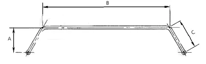
vii) We need a solid anti-roll bar, hence we set the inner diameter to zero. The outer diameter value was altered till we get a good anti-roll stiffness.
3. Pitch Analysis:
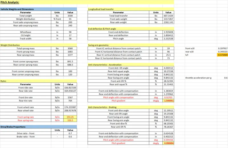
i) First, the longitudinal load transfer is determined which gives the front and rear axle weight.
Total load trasnfer,
`LT_(lon) = (W*h)/(WB)`
where,
`W ->` Total weight (lbs)
Front axle weight,
`W_f = (%Front * W)/100 -LT_(lon)`
Rear axle weight,
`W_r = (%Rear * W)/100 + LT_(lon)`
ii) Once we know the load transfer, we can calculate the front and rear end deflections. The pitch angle can be determined from the deflections.
End deflection,
`z = (LT_(lon))/(2*k_w)`
Pitch angle,
`theta = arctan((z_f + z_r)/(WB))`
where,
`z_f, z_r ->` Front and Rear end deflection respectively
iii) The side view swing arm geometry for both front and rear is set up using ballpark values while achieving the target values.
iv) The anti characteristics define the resistance of the vehicle against pitching motion.
Acceleration-
Front Anti-lift angle,
`theta_(AL) = arctan((IC_(V_f) - r_t)/(IC_(H_f)))`
where,
`IC_(V_f) ->` Front IC vertical distance from contact patch
`IC_(H_f) ->` Front IC horizontal distance from contact patch
`r_t ->` Tire radius
Rear Anti-squat angle,
`theta_(AS) = arctan((IC_(V_r) - r_t)/(IC_(H_r)))`
`IC_(V_r) ->` Rear IC vertical distance from contact patch
`IC_(H_r) ->` Rear IC horizontal distance from contact patch
Swing arm angle,
`theta_s = arctan(h/(WB))`
% Front anti-lift `= (theta_(AL)*phi_d*100)/theta_s`
% Rear anti-squat `= (theta_(AS)*(1-phi_d)*100)/theta_s`
where,
`phi_d ->` Drive ratio
Braking-
Front anti-dive angle,
`theta_(AD) = arctan((IC_(V_f))/(IC_(H_f)))`
Rear anti-squat angle,
`theta_(AS) = arctan((IC_(V_r))/(IC_(H_r)))`
% Front anti-dive `= (theta_(AD)*phi_b*100)/theta_s`
% Rear anti-squat `= (theta_(AL)*(1-phi_b)*100)/theta_s`
where,
`phi_b ->` Braking ratio
v) The end deflections with compensation for both the cases (acceleration & braking) are calculated
`z_(comp) = (z*(100-%(anti-parameter)))/100`
where,
`z ->` can be front or rear end deflection for the corresponding anti-parameter
vi) The pitch angle with compensation is calculated. For pitch gradient, we consider throttle acceleration per g to be 0.6. The final pitch gradient is calculated.
All the parameters are optimised to achieve the target pitch gradient values.
The calculations were done in an excel sheet.
Excel sheet (sanpshots):
The excel file can be found in the following Google drive link-
Excel sheet (drive link): ( https://drive.google.com/file/d/13sufMVUBweBO9IM8w-FPdlcFbWUA-cx1/view?usp=sharing )
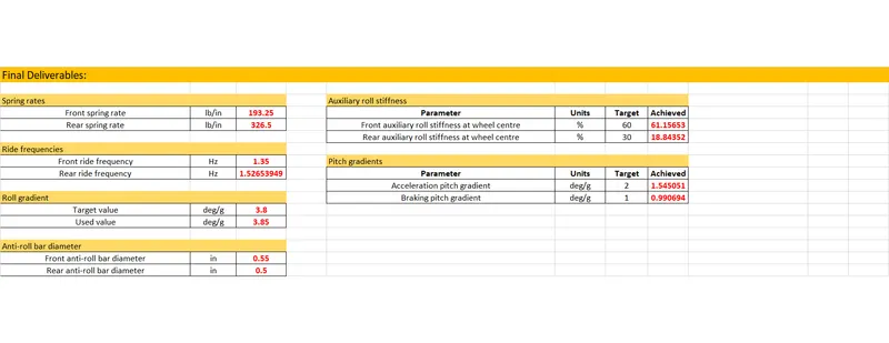
FINAL DELIVERABLES:
| Spring rates | |||
| Front spring rate | lb/in | 193.25 | |
| Rear spring rate | lb/in | 326.5 | |
| Ride frequencies | |||
| Front ride frequency | Hz | 1.35 | |
| Rear ride frequency | Hz | 1.52653949 | |
| Roll gradient | |||
| Target value | deg/g | 3.8 | |
| Used value | deg/g | 3.85 | |
| Anti-roll bar diameter | |||
| Front anti-roll bar diameter | in | 0.55 | |
| Rear anti-roll bar diameter | in | 0.5 | |
| Auxiliary roll stiffness | |||
| Parameter | Units | Target | Achieved |
| Front auxiliary roll stiffness at wheel centre | % | 60 | 61.15653 |
| Rear auxiliary roll stiffness at wheel centre | % | 30 | 18.84352 |
| Pitch gradients | |||
| Parameter | Units | Target | Achieved |
| Acceleration pitch gradient | deg/g | 2 | 1.545051 |
| Braking pitch gradient | deg/g | 1 | 0.990694 |
CONCLUSION: The springs and anti-roll bars were selected which met the targets and were all in the given limits.