Vehicle Dynamics - Final Project - Design of ARB to meet target roll gradient and Selection of K&C parameter to meet the target Understeer Budget
The excel file link is as follows :
https://drive.google.com/file/d/1hOziM_YhsHSHBXvX2V9lySka3kb6s30R/view?usp=sharing
Objective of the project :
The aim of the project is to select anti-roll bar diameters to meet the target roll gradient and also to selection appropriate kinematic and compliance parameters to meet the target understeer budget.
Introduction :
The first objective in the project is the selection of the anti-roll bars for a lightweight sports car . The constriant for maximum auxillary roll stiffness are specified under the vehicle level targets. The anti-roll bars have to selected such that they would provide this required auxillary roll stiffness for given spring rates. Then the tire-stiffness values are plotted to study the variation of the stiffness values ( cornering stiffness, camber stiffness, aligning moment stiffness) with the normal load. Finally the understeer budget is prepared based on the kinematic and compliance characteristics, tire stiffness values and the roll gradient of the car. Further the effect of all these individual parameters is studied inorder to achieve a net understeer effect on the vehicle.
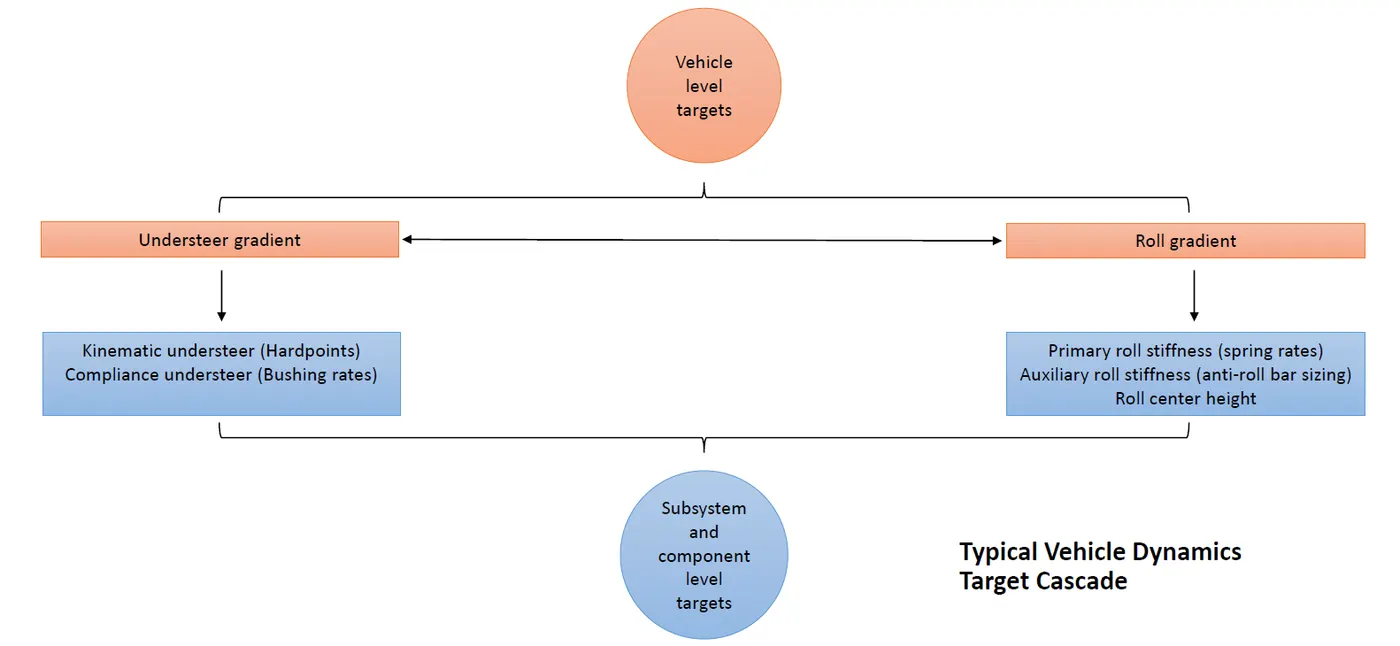
The below flow chart depicts a typical vehicle dynamics target cascade.
The deliverables in the project are as follows :
- Roll bar diameters
- Primary and secondary roll stiffness at the wheel center.
- Auxillary roll stiffness percentage.
- Tire stiffness plots
- Understeer budget sheet.
The Target and Constraints are as follows :
| Target parameters | Units | Target |
| Roll Gradient | deg/g | 3.5 - 3.8 |
| Understeer Gradient at tires | deg/g | Maximum possible |
| Parameter (constriant range) | Front | Rear |
| Auxillary roll stiffness front (%) | 60 | 25 |
| Auxillary roll stiffness rear(%) | 20 | 0 |
| Roll steer front (%) | 6.5 | 3 |
| Roll steer rear (%) | -4 | -8 |
| Roll camber front (%) | 90 | 80 |
| Roll camber rear(%) | 65 | 50 |
| Lateral force compliance steer front (deg/KN) | 0.05 | 0.008 |
| Lateral force compliance steer rear (deg/KN) | 0.04 | 0.015 |
| Lateral force compliance camber front (deg/KN) | 0.3 | 0.1 |
| Lateral force compliance camber rear (deg/KN) | 0.4 | 0.15 |
| Aligning torque compliance steer front (deg/100Nm) | 0.4 | 0.2 |
| Aligning torque compliance steer rear (deg/100Nm) | 0.1 | 0.06 |
Roll Analysis :
From the springs rates the primary roll stiffness at the front and rear is calculated. Based on the roll gradient target given , the roll stiffness contribution due to anti-roll bar is calculated. It must be made sure that the percentage of auxillary roll stiffness( Anti-roll bar) is within the constraint limits. If not the primary roll stiffness has to be tuned, which is done by changing the spring rates, but while keeping the target of the front ride frequency in check. Then based on the auxillary stiffness, the anti-roll bar diameter is calculated.
When a vehicle encounter a corner, a lateral load transfer occurs due to the lateral acceleration experienced during cornering. The load transfer is the shifting of the total normal load around the vehicle during cornering. In otherwords its the `deltaW` by which the vertical load on the outer tyres increased and reduced from the inner tyres while cornering.
The total lateral load transfer = `TotalLLT=(δW)/A_y = (W⋅h)/t`
In this case the total load transfer calculated to be 1025.086 lbs. To induce an understeer into the vehicle, we add an extra 5% to the front side. Hence the total load transfer to the front is calculated to be 666.36 lb/g
The total load transfer cannot be changed much one the vehicle is built. This might include changing the CG height and trackwidth. But instead of that inorder to improve the handling of the car, the focus can be shifted towards the different components of the lateral force and the lateral load distribution between the front and the rear. The total load transfer has three components - lateral load transfer due to unpsrung mass. lateral load transfer from direct lateral force and lateral load transfer due to body roll.
Lateral load transfer due to unsprung mass : This component of the lateral load transfer is not a tunable parameter because adding or reducing the unsprung mass will affect the wheel hop frequency and this in turn affects the tire contact and grip.
Lateral load transfer due to unpsrung mass = `LLT_(unsprung) = (W_(us)⋅Z_(us))/t`
Lateral transfer from direct force : It is a component that relates the lateral force acting on the sprung mass. It arises from the force coupling effect that roll centres have, directly linking forces on sprung mass to the unsprung mass. Its also called the kinematic load transfer component. The lateral force acting on the sprung mass will generate a moment on the tires through the roll centre height.
Lateral load transfer due to direct lateral force = `LLT_(sprung)=(Ws⋅Zrc⋅(l−x))/(t⋅l)`
Where `W_s* Z_(rcf)`is the sprung mass, `W_(us)*Z_(rcr)`is the unsprung mass, `Z_(us)` is the CG height of the unsprung mass,`t` is the trackwidth, is the height of the roll centre and `l` is the wheelbase of the vehicle.
These components of the lateral forces were calculated for the given input data and are as follows :
- Lateral force transfer due to unsprung mass = 39.56 lb/g
- Lateral load transfer from direct force = 12.536 lb/g
Lateral load transfer due to body roll : As the vehicle encounters a corner, the inertia of the vehicle generates a moment, that causes the vehicle to roll towards the outside. This makes the spring to generate forces, which inturn resists the roll of the vehicle. These forces upon the spring is reacted at the tires, which causes a lateral load transfer. This is also called as the elastic weight transfer component.
Lateral load transfer due to body roll =`LLT_(bodyroll) = (k_(ϕa)⋅W_s⋅h_(arm))/ (t⋅(k_(ϕf)+k_(ϕr)−(W_s⋅h_(arm))).`
Where `k_(ϕa)*(W⋅h)/t = ((W_(ua)⋅Z_(us))/t) + (W_s⋅Z_(rc)*(l−x))/(t⋅l) + ((k_(ϕa)⋅W_s⋅h_(arm))/(t⋅(k_(ϕf) + k_(ϕr) −(W_s⋅h_(arm)))))`is the roll stiffness in that particular axle(front or rear). `k_(ϕf)` is the front roll stiffness , `k_(ϕr)`.
`LLT_(bodyroll) = (k_(ϕa)⋅W_s⋅h_(arm))/(t⋅(k_(ϕf)+k_(ϕr)−(W_s⋅h_(arm)))) = (k_(ϕa)⋅ϕ)/t`is the rear roll stiffness, `h_(arm)` is the torque arm length and `h` is the CG height.
The h_arm is the torque arm length and is calculated by using the following equation :
`h_(arm)=h_s−Z_(rcf)−((a_s/l)⋅(Z_(rcr)−Z_(rcf)))`
Where `M_ϕ=k_ϕ⋅ϕ` is the front roll centre height, is the rear roll centre height and `a_s` is the longitudinal distance between the CG point and front axle.
`h_s`is the sprung mass CG height, which is calculated using the equation :
`h_s = ((W_T⋅h)−(W_(ur)⋅RL_r)−(W_(uf)⋅RL_f))/W_s`
Where `W_T` is the total vehicle weight, `RL_r` and `RL_f` is the tire loaded radius in the rear and front respetively.
The total lateral load transfer equation is given by :
The total lateral load transfer is obtained from vehicle weight, CG-height and trackwidth. We add 5% of Total lateral load transfer to this as mentioned . This extra 5% of TLLT is to induce understeer in the vehicle. Then the lateral load transfer component is subtracted by the lateral load transfer components due to sprung and unsprung mass. Then we get the lateral load transfer due to body roll.
`LLT_(bodyroll)=TotalLLT−LLT_(unsprung)−LLT_(sprung)`
Using the equation, the total load transfer due to the body roll is calculated to be 614.2 lb/g.
We already know from the previous equations that :
Where `ϕ` is the roll gradient which is one of the vehicle level targets.
from the above calculation steps the front roll stiffness is found. The front roll stiffness in this case is 771.08 ft-lb/deg.
When cornering, the sprung mass of the car will roll by an amount `ϕ`the roll angle. This is reacted by the roll stiffness `K_ϕ`of the car. Roll stiffness is defined as the resistance moment generated per unit of roll angle of the sprung mass. Further the total vehicle roll stiffness is calculated and then rear roll stiffness can be calculated based on the below mentioned equations`
Roll moment =`M_(phi) = k_(phi)*phi` Where `M_ϕ` is the roll moment and `k_ϕ` is the total roll stiffness. The total roll stiffness is equal to the sum of front and rear roll stiffness.
The roll moment has two components, namely the lateral component and then a gravity component.
Roll moment =`M_ϕ=W_s⋅h_(arm)⋅A_y⋅cos(ϕ)+W_s⋅A_y⋅h_(arm)⋅sin(ϕ)`. For small angles `cos(ϕ)=1andsin(ϕ)=ϕ`. Further substituting this the total roll moment is calculated.
Rearranging the set of equation we get :`k_ϕ=(W_s⋅h_(arm)+W_s⋅h_(arm)⋅ϕ)/ϕ`
The total roll stiffness is equal to 1249.024 ft-lb/deg. The rear roll stiffness and the front roll stiffness put together gives the total roll stiffness. So the rear roll stiffness can be calculated by subtracting the front roll stiffness from the total roll stiffness. The rear roll stiffness is 477.93 ft-lb/deg.
This stiffness is the combined stiffness of the tires, spring and the anti-roll bar. The roll stiffness contribution by the springs are called the primary stiffness and the roll stiffness contributed by the anti-roll bar is called as the auxillary stiffness. The contribution of the tire has to be isolated.
The general equation for the above setup is : `1/k_(ϕf) = (1/k_(ϕwc)+1/k_(ϕtire))`.
The front roll stiffness at the wheel centre is given by : `k_(ϕwc)=(k_(ϕtire)⋅k_(ϕf))/(k_(ϕtire)−K_(ϕf))`
The front roll stiffness at the wheel centre is a sum of the roll stiffness due to springs and the anti-roll bars.
`k_(ϕwc)=k_(ϕs)+k_(ϕarb)`
Where `k_(ϕs)` is the roll stiffness contribution / primary stiffness at the wheel centre. While `k_(phiarb)` is the roll stiffness contribution due to anti-roll bar / auxillary stiffness at the wheel centre. The primary stiffness can be calculated using the below mentioned equation.
`k_(ϕs) = (k_s⋅t^2⋅MR^2)/2`
Further auxillary stiffness can be calculated : `k_(ϕwc)−k_(ϕs) = k_(ϕarb).`
The primary and auxillary roll stiffness in the front is calculated to be 551.96 ft-lb/deg and 462.701 ft-lb/deg. Whereas in the rear side the primary and auxillary roll stiffness is calculated to be 469.7 ft-lb/deg and 91.78 ft-lb/deg.
The contribution of the auxillary stiffness is checked at the front and rear, as it must not go beyond the contraint limits.
The primary roll stiffness (%) is given by : `(k_(ϕs)/k_(ϕf))⋅100`
Similarly the auxillary roll stiffness (%) is given by : `(k_(ϕarb)/k_(ϕf))⋅100`
Once the percentage is within the constraints the anti-roll bar is then designed for this auxillary stiffness. If not the percentage contriubution of primary roll stiffness is increased, so the percentage contribution by the auxillary stiffness will reduce. This can be done by changing the spring ride rates. Again ride analysis will have to be performed to meet the targets of both the ride and roll analysis keeping the constraints under check.
In the design proposed under this project, the maximum auxillary stiffness (%) at the front is 61.48% and the maximum auxillary stiffness(%) at the rear is 20.49%. According to the constraints, the auxillary stiffness in the front has to be constrainted between 25-60% and in the rear it has be constrainted between 0-20%. For this setup above, the auxillary roll stiffness is at the higher end. In order to reduce the auxillary roll stiffness contribution either the spring rate has to be changed, or the roll gradient has to be increased. The spring rates cannot be increased, as they are given as input in this case. The roll gradient has to be increased beyond 3.8deg/g, as doing so there is deviation from the target.
For given value of spring rates there are two possible setup options that is possible :
- The vehicle is designed for a roll gradient of 3.8deg/g, with the front auxillary roll stiffness contribution to be 61.48% and rear auxillary roll stiffness contribution to be 20.49%. In this case there is slight deviation from the allowable constraint range for auxillary roll stiffness contribution values.
- The other option is to reduce the value of front auxillary roll stiffness contribution to be 60% and rear auxillary roll stiffness contribution to be 19.2%. This can be done by increasing the roll gradient to 3.85deg/g. In this case there is a slight deviation from the roll gradient target which has to be between 3.5deg/g to 3.8deg/g. There is a deviation of 1.31% from the target. This deviation is allowed as it is within the 5% .
The second option is chosen as the best setup for the given conditions ( constraints and target). The values of various parameters mentioned above are calculated for this second option ( roll gradient of 3.85 deg/g).
Design of anti-roll bar: Antiroll bars are generally added to the car to make it stiffer in roll without altering the ride characteristics. The diameter of the ARB( anti-roll bar) can be calculated from the below mentioned equation.
`k_(ϕarb) = (500000⋅(OD)^4)/((0.4422⋅A^2⋅B)+(0.2264⋅C^3))⋅2⋅MR^2⋅(t^2/2)`
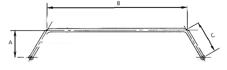
In this case we are considering the ID = 0. OD is the outer diameter (in), 'A' is the virtual torque arm(in), 'B' is the central length (in) and 'C' is the physical torque arm(in), 't' is the vehicle trackwidth(in) and `k_(ϕarb)` is the auxillary stiffness (in-lb/deg).
In this case the case the outer diameter of the anti-roll bar in the front is 22.76mm and the outer diameter in the rear is 13.44mm.
TIRE STIFFNESS CURVES
The tire stiffness curves are very important part of tire modelling. The values from the results of the tire modelling are used in vehicle design. In this case for the calculation and tabulation of the understeer budget the following tire stiffness curves have to be studied :
- Cornering stiffness vs vertical load : When the lateral forces acts on the tire contact patch, it causes distortion. This distortion causes the slip angles. Due to this the thread elements of the tire (as per the brush model thoery) are deflected sideways, thereby generating the lateral stress. A property of primary importance to the tuning and stability behaviour of a motor vehicle is the initial slope of the lateral force curve. The slope of that curve evaluated at zero slip angle is known as the cornering stiffness. The cornering force at a given slip angle rises with vertical load on the tire, it does not rise proportionately with load. As the vehicle is manuvered, there is dynamic shift in the vertical load, and as the vertical load varies the cornering stiffness also varies. Hence its become important to monitor the plot of cornering stiffness versus vertical load.
Characteristically, the stiffness versus load curve is always concave down, the analysis of the plot becomes important while tabulating the understeer gradient of the vehicle. Based on the values given, the below plot of tire cornering stiffness vs load is plotted. Then curve fitting is done to obtain the equation of the curve. By using the equation, the value of cornering stiffness for any given vertical load can be calculated.
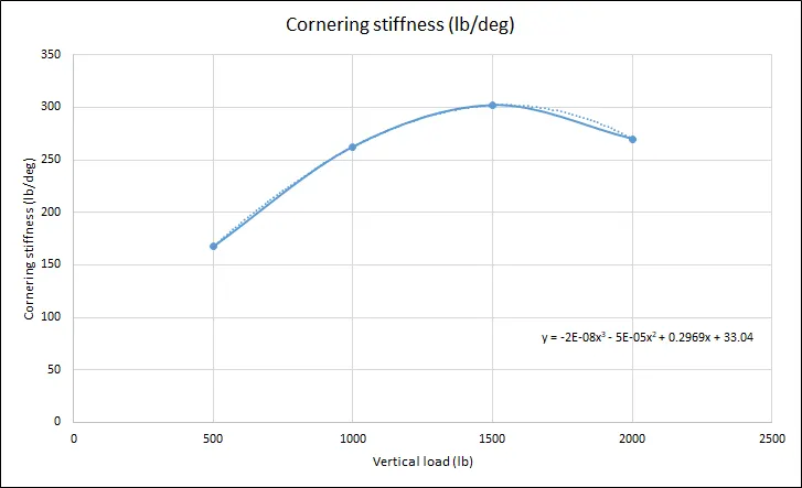
The equation obtained by curve fitting is shown alongside the plot, where 'y' is the cornering stiffness in lb/deg and 'x' is the vertical load in lbs.
Camber stiffness vs vertical load : Apart from slip angles, another means of generating the lateral force in a tire is from the rolling in a non-vertical orientation, in an inclination angle called as the camber angle. With camber, the lateral force generated is known as the camber thrust. This lateral force due to the camber angle is also charactersited by the initial slope of the lateral force versus camber curve. The slope is termed as the camber stiffness. The magnitude of camber stiffness is around 10-15% of the cornering stiffness.
Camber stiffness also varies with vertical load for a given camber angle. But this extent of variation is less when compared to the cornering stiffness. The plot between the camber stiffness versus vertical load is given below along the equation of the curve which is obtain by the curve fitting method. The equation can be used to obtain the camber stiffness value for any given vertical load.
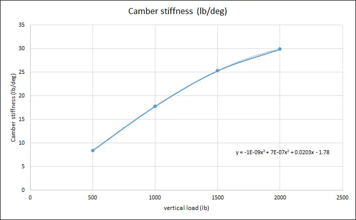
The equation obtained by curve fitting is shown alongside the plot, where 'y' is the camber stiffness in lb/deg and 'x' is the vertical load in lbs.
Alignign moment stiffness vs vertical load: The lateral force acts at a point behind the centre of tire contact, this gives rise to aligning moment. Aligning moment is the produced of the lateral force generated at the tire contact patch and the trail ( pneumatic + castor). The aligning moment always attempts to steer the tire in the direction it is travelling, thus it has a stabilizing influence on a vehicle. The aligning moment varies with the size of the contact patch. The vertical load has an influence on the contact patch area.
So hence as the vertical load increases, the contact patch increases. This causes an increase in the aligning moment. The sensitivity of the aligning moment to the vertical load is shown in the below plot between the aligning moment stiffness and the vertical load.
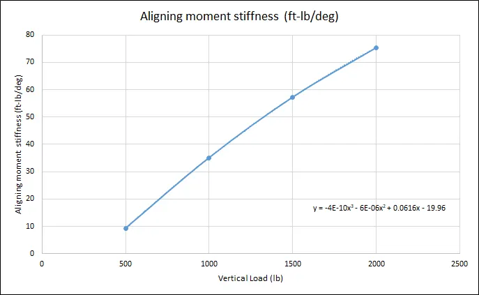
The equation obtained by curve fitting is shown alongside the plot, where 'y' is the aligning moment stiffness in ft-lb/deg and 'x' is the vertical load in lbs.
UNDERSTEER BUDGET :
The understeer budget sheet gives the information about the contribution of the various parameters towards the total understeer gradient of the car. It becomes an efficient tool to tabulate these contribution and based on these contribution, the necessary changes in the suspension hard points and bushing rates. The various parameters are as follows :
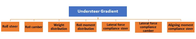
Roll steer
When a vehicle corners, the suspension kinematics is such that the vehicle steers. Roll steer is defined as the steering motion of the front or the rear wheels due to the rolling motion of the vehicle. The steer angle affects the handling characteristics of the vehicle causing an understeering or an oversteering effect. The understeer gradient contribution from the roll steer is as follows :
Contribution of roll steer towards understeer gradient = (degree of steer/ degree of roll)*Roll gradient.
`K_(rollsteer)=(ε_f−ε_r)⋅(dϕ)/(d(A_y))`
Where, `K_(rollsteer)` is the understeer gradient due to roll steer , `ε_f` and `ε_r`is the roll steer percentage in front and rear respectively. `(dϕ)/(dA_y)`
A positive roll steer in the front causes understeer. On the other hand a positive roll steer in the rear causes oversteer. Hence the roll steer in the front and rear are subtracted to yield in net understeer gradient.
Lateral force compliance steer
Generally in passenger cars, in order to achieve good ride quality and NVH quality, bushings are used. This gives rise to compliance. Depending on the relative stiffness between the suspension and steering systems and the location of the steering rack, the vehicle may either understeer or oversteer. If the front is more compliant, then it toes-out to the lateral force, which causes the vehicle to understeer.
The handling influence of the lateral force compliance steer is quantified by a coefficient known as the lateral force compliance steer coefficient ( which is a ratio of the steering angle to that of the lateral force acting on the tire). Lets consider this coefficient to be Af and Ar in the front and rear respectively. The understeering arising from this compliance steer is given as :
`k_(lfcs) = A_f⋅F_(yf)−A_r⋅F_(yr)`
Where `k_(lfcs)` is the understeer gradient due to lateral force compliance steer, `A_f` and `A_r` is the lateral force compliance steer coefficient, and `F_(yf)` and `F_(yr)` is the lateral force produced in the front and the rear tires.
Aligning Torque
The aligning torque always resists the attempted turn and hence always causes an understeer effect. The aligning torque is defined as the product of lateral force and pneumatic trail. The lateral force is generated at a point behind the tire centre, that distance is defined as the pneumatic trail. This torque always resists the turn, and hence contributes to the understeer budget. The understeer gradient due to the aligning torque is given by :
`K_(at) = (AT_f+AT_r)/(L⋅C_(αf)) + (AT_f+AT_r)/(L⋅C_(αr))`
Where katkat is the understeer gradient due to aligning moment, `AT_f` and `AT_r` is the aligning moment in the front and the rear wheels respectively, `C_(αf)` and `C_(αr)`is the tire stiffness in the front and rear respectively, and LL is the wheelbase of the vehicle. In this case the effect produced at the front and the rear are added, because the aligning moment at all times attempts to resist the turn, thereby always producing an understeer.
Roll moment distribution
For all pneumatic tires, the cornering forces are dependent on the vertical load acting on it. The relation is non-linear. During cornering, there is transfer of the load from the inner tires to the outer tires and during hard cornering conditions the average lateral force from both the tires reduces. As the following example, wherein the average lateral force generated is 760lb at a slip angle of 5 degrees. During the hard cornering, due to the tire load sensitivity property, the average lateral force reduces to 680lb. Due to this the tires which assume a greater slip angle to maintain the necessary lateral force for the turn.
- If this happens in the front tires, then the front will plough out and the vehicle will understeer.
- If this happens in the rear tires, the rear will slip out and the vehicle will oversteer.
The net contribution depends on the roll moment distribution between the front and the rear axles. More roll moment in the front causes understeer, whereas if the roll moment is more in the rear, it causes oversteer. Anti-roll bars(ARBs) control the handling characteristics of the vehicle through this mechanism.
Weight distribution :
The contribution due to this factor is given the ratio between the vertical load on the tire to that of the tire cornering stiffness. The cornering stiffness in turn varies with the vertical load. This parameters is one of the main contributors to the understeer of the vehicle. The understeer gradient contribution is given as follows :
`K_(wd) = (W_f/C_(αf)) − (W_r/C_(αr))`. Where `K_(wd)` is the understeer gradient due to weight distribution. `W_f` and `W_r`is the weight on the front and the rear wheels. `C_(αf)` and `C_(αr)` is the tire stiffness in the front and rear respectively.
Roll camber :
When a camber angle is given, this in turn produces a lateral force component known as the camber thrust. The camber thrust varies with the camber angle. During cornering, the camber angle also changes. The camber angle per roll angle thus becomes an important parameter.
`krc=(d_(γf)/d_ϕ)⋅(d_ϕ/(dA_y))⋅(C_(γf)/C_(αf))−(d_(γr)/d_ϕ)⋅(d_ϕ/(dA_y))⋅(C_(γr)/C_(αr))`
Where , `k_(rc)` is the understeer gradient due to roll camber, `γ_f` and `γ_r` is the camber angle in the front and rear, `ϕ` is the roll angle, `A_y` is the lateral acceleration, `C_(γf)` and `C_(γr)` is the camber stiffness at the front and rear tires, `C_(αf)` and `C_(αr)` is the tire stiffness in the front and rear respectively.
Lateral Force Compliance camber:
During cornering the lateral forces acts at the tire contact patch. This causes the tire to tilt out, as all the compliant components are above the ground, generating a positive camber. This also reduces the tire grip and hence the cornering capability of the tire reduces. The more compliant it is , more lose in the cornering capability.
`k_(lfc c) = B_f⋅F_(yf)⋅(C_(γf)/C_(αf))−B_r⋅F_(yr)⋅(C_(γr)/C_(αr)).`
Where `k_(lfc c)`is the understeer gradient due to lateral force compliance steer `B_f`and `B_r` is the lateral force compliance camber coefficient``C_(γf)` and `C_(γr)` is the camber stiffness at the front and rear tires, `C_(αf)` and `C_(αr)` is the tire stiffness in the front and rear respectively.
If the front is more compliant than the rear it produces a understeer. On the other hand, if the rear is more compliant than the front, it produces an oversteering effect.
Aligning torque compliance steer:
Aligning moment always try to straighten the wheels , hence it always produces an understeer effect in the front and always produces an oversteer effect at the rear. The understeer contribution of the aligning torque compliance steer is given by:
`k_(atcs)=(C_f⋅AT_f)−(C_r⋅AT_r)`
where `k_(atcs)` is the understeer gradient due to aligning torque compliance steer, `C_f`and `C_r`is the aligning torque compliance steer coefficient, `AT_f and AT_r` is the aligning moment produced in the front and the rear tires.
For calculating these terms, part of the data is required from the kinematic and compliance testing. In kinematic and compliance testing, a known displacement and force is applied and the position changes at the wheel centre is observed. So for preparing the understeer budget, from the kinematic side, the data required is regarding the roll steer , roll camber and roll weight transfer. Whereas on the other hand from the compliance side, the data required is the lateral force compliance steer, lateral force compliance camber and the aligning torque compliance steer.
The understeer gradient due to all these parameters are calculated based on the results from above and the kinematic and compliance characeteristics. The understeer budget sheet is tabulated as follows .
| Parameters | Front | Rear | Understeer gradient | Contribution (%) |
| Weight distribution | 3.519 | 3.077 | 0.443 | 21.94 |
| Roll steer | 0.250 | -0.308 | 0.558 | 27.67 |
| Roll camber | 0.216 | 0.101 | 0.115 | 5.71 |
| Aligning torque | 0.073 | -0.096 | 0.169 | 8.37 |
| Lateral force compliance steer | 0.188 | 0.036 | 0.152 | 7.54 |
| Lateral force compliance camber | 0.070 | 0.019 | 0.052 | 2.55 |
| Aligning torque compliance steer | 0.559 | 0.030 | 0.529 | 26.21 |
| Total Understeer gradient | 2.017 deg/g | |||
The same is represented in a contribution chart as follows :
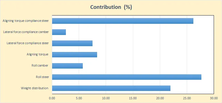
The above plot gives the contribution of each parameter towards the understeer gradient. This chart is analysed and then the bushings and suspenions hardpoints are modified accordingly to obtain the required understeer gradient.
RESULT:
| Parameter (constriant range) | Maximum | Minimum | Final value selected |
| Auxillary roll stiffness front (%) | 60 | 25 | 60 |
| Auxillary roll stiffness rear(%) | 20 | 0 | 19.20 |
| Roll steer front (%) | 6.5 | 3 | 6.5 |
| Roll steer rear (%) | -4 | -8 | -8 |
| Roll camber front (%) | 90 | 80 | 90 |
| Roll camber rear(%) | 65 | 50 | 50 |
| Lateral force compliance steer front (deg/KN) | 0.05 | 0.008 | 0.05 |
| Lateral force compliance steer rear (deg/KN) | 0.04 | 0.015 | 0.015 |
| Lateral force compliance camber front (deg/KN) | 0.3 | 0.1 | 0.3 |
| Lateral force compliance camber rear (deg/KN) | 0.4 | 0.15 | 0.15 |
| Aligning torque compliance steer front (deg/100Nm) | 0.4 | 0.2 | 0.4 |
| Aligning torque compliance steer rear (deg/100Nm) | 0.1 | 0.06 | 0.06 |
The final target values attained is as follows :
| Target parameters | Units | Target | Final value |
| Roll Gradient | deg/g | 3.5 - 3.8 | 3.85 deg/g (the deviation is within 5%) |
| Understeer Gradient at tires | deg/g | Maximum possible | 2.017 deg/g |
The anti-roll bars diameters has to be as follows to meet the above vehicle target while tuning the vehicle within the given range of the constraints :
| Anti-roll bar | Outer Diameter |
| Front Anti-Roll bar | 22.75 mm |
| Rear Anti-roll bar | 13.50 mm |