Vasavi_External Exam_Tekla
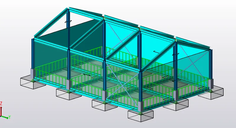
Analyze and Design a Boiler shed structure as per IS code in Tekla Structural Designer. Kindly refer to the enclosed plan and elevation given below for modelling.
A)
AIM: To Analyze and Design a Boiler shed structure as per IS code in Tekla Structural Designer by refering to the enclosed plan and elevation given below for modelling.
TOOLS REQUIRED:
PROCEDURE:
1. Primarily ley us open the tekla software and create a new file in tekla software using new icon present in file toolbar
2. Now let us model grid lines using grid icon present in model toolbar acc to our plan.
3.once grid lines are modelled let us model construction levels using elevation view
TOOLS REQUIRED:
FILE
OPEN
SAVE AS
CONSTRUCTION LEVEL
PROJECT BROWSER
PROPERTY WINDOW
VALIDATE
GRID
AREA LOADING
LOAD
WIND LOAD
BEAM
COLUMN
FOUNDATION
LOAD CASES
LOAD COMBINATIONS
SLAB
ANALYSIS
PILE BASE COLUMN
PROCEDURE:
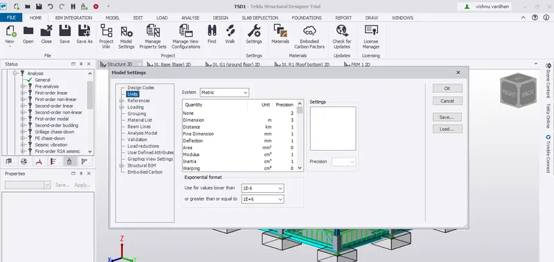
1. Open a new file in Tekla software by selecting the new icon from the File toolbar.once the a new file is created we have check some settings like units for that let us make use of settings tab present in home toolbar
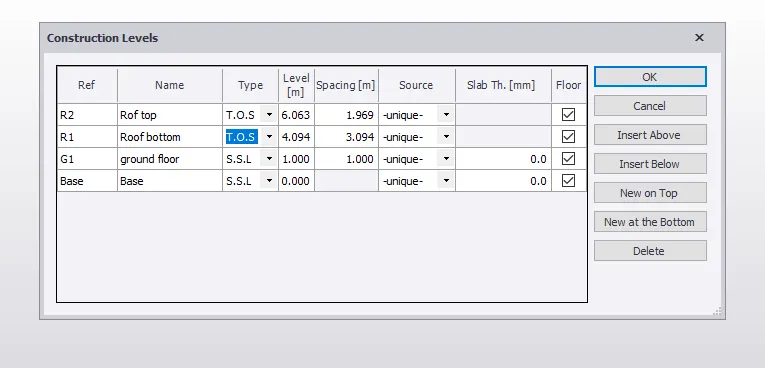
2. primarily let us assign construction level using construction level icon present in the model toolbar with the help of crossectional view of the given attachment and click on ok once it is done.
3. Once the construction levels aRE modelled ,Now select the grid icon from the model toolbar and model grid according to the model and can be drawn in any of the construction level by choosing it from project browser
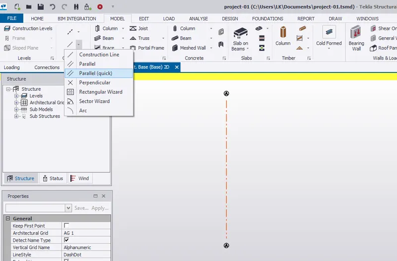
and dimension thyem using dimension icon
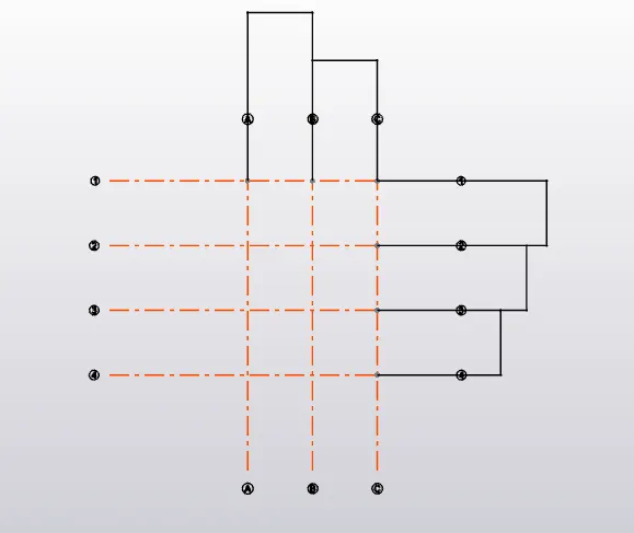
4. now let us model column for our model
before modeling the column let us make use of manage property sets tab present in home toolbar and generate a new column by varying properties according to our model.
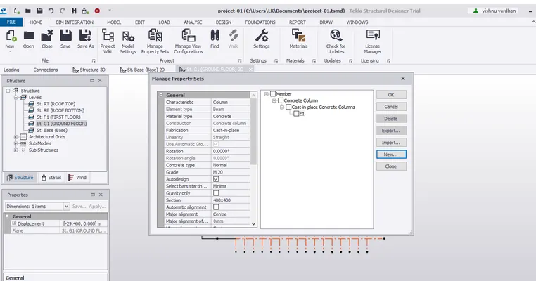
5.now let go to base level which can be accessed with the help of project browser and then select column icon and model them with the help of grid lines modeled.
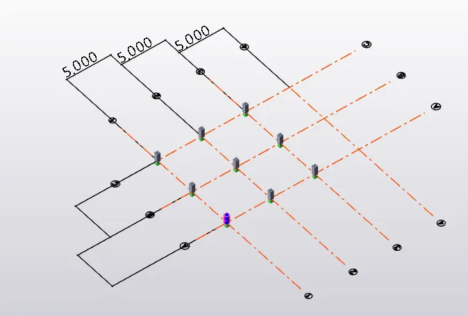
6. Now let us model steel columns so similar to model of concrete columns we will model steel columns by creating a steel column with different properties by manage property sets and model it our structure,
make use of property window to change its properties
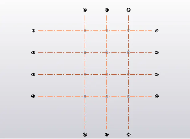
in 3d view
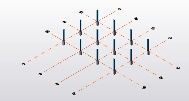
7. Now let us model beams for that we firstly generate a new kind of beam by going to manage property set icon and now select beam icon from the model toolbar and locate the beams, we can change its properties if is necessary.
so firstly model it in a construction level (ground floor)
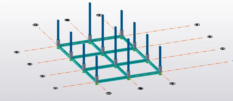
now let us model rafter beams for our model let us make use of frames
8. now similarly model rafter beams by creating a new property of beam using manage property sets
we can make use of frame icon for it.
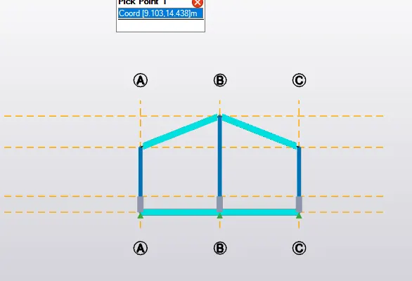
and simply do it for other columns using copy icon present in edit toolbar.
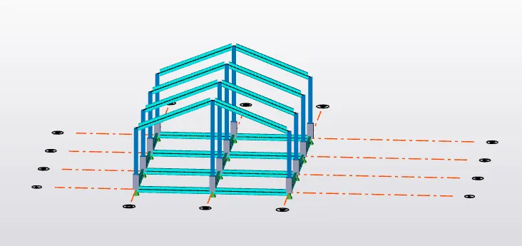
final output of beams and columns
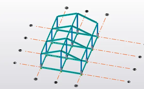
10. now let us model roof pannels using the roof panel icon present in model toolbar
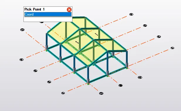
11. now let us model wall panels similarly for all corners of the member, do it for all the members
And now model bracings to the model for that simply select bracing icon present in model toolbar
and for modeling simply select all the corners of the member for which we are modeling bracing
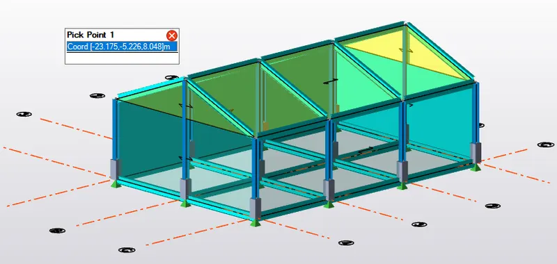
now model bracings to the model for that simply select bracing icon present in model toolbar
and for modeling simply select all the corners of the member for which we are modeling bracing
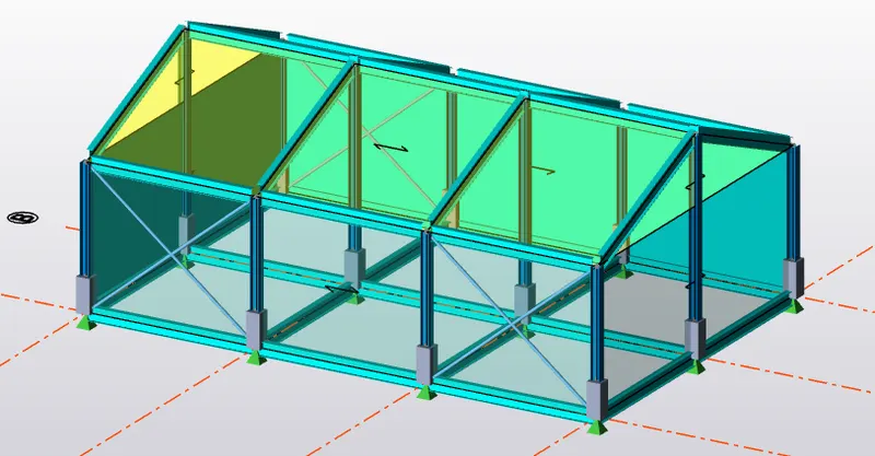
12. now let us model slabs to our model by using slab on beam icon
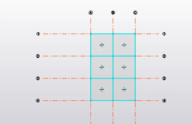
validate the model after each step to avoid errors in the model.
13. let us apply loading to the model by refering to IS CODE, for this let us choose load icon followed by selecting load cases option
DEAD LOAD
add a new load case and name it as dead load and assign it type of load as dead
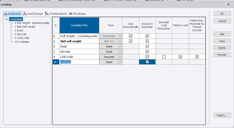
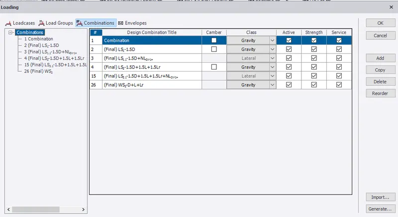
14. then before applying loads let us check load combinations click on load combinations that we want to be imported for the model
and then click ok.
15. Now let us apply dead load to our model for this we have to select dead load from the down box and as per IS code
the calculations for dead load
# brick wall loading for 150 mm thick
# FINISHERS SAY 50 MM
SO LOAD TO BE APPLIED=0.05 x 24=1.2KN/M
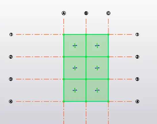
FROM GROUND FLOOR TO FIRST FLOOR
HEIGHT X UNIT WEIGHT X BRICKWALL THICKNESS
= 4.094 M X 20KN X 0.15M=12.8 KN/M
SO PRIMARILY APPLY IT TO GROUND FLOOR.
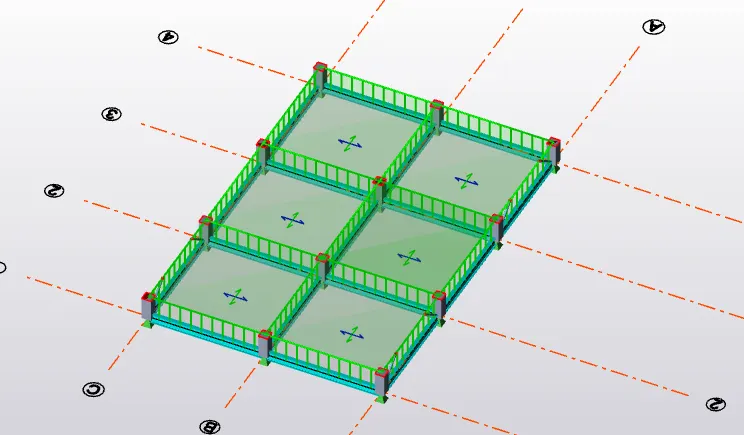
dead load for the model is applied
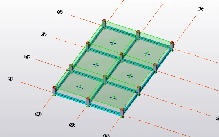
16. now similarly let us apply live load for different rooms as per IS code, for this we can make use of area load
and apply it for the ground floor, first floor
similarly, let us apply load on roofs
make use of area load as per IS CODE(IS 875)
say kitchen-5KN/m
bed room-5 KN/M
living room=5 KN/M etc.
17. for applying wind loads we must perform calculations first let us make use of wind wizard icon and
then a new dialog box appears with the details taken from the model by tekla itself we can change its values
in dialog box and click finish

18. Now let us perform analysis for this let us check for some settings before performing analysis
for this go to the settings icon and check for tolerance, iterations, modification factor as assign to 1.
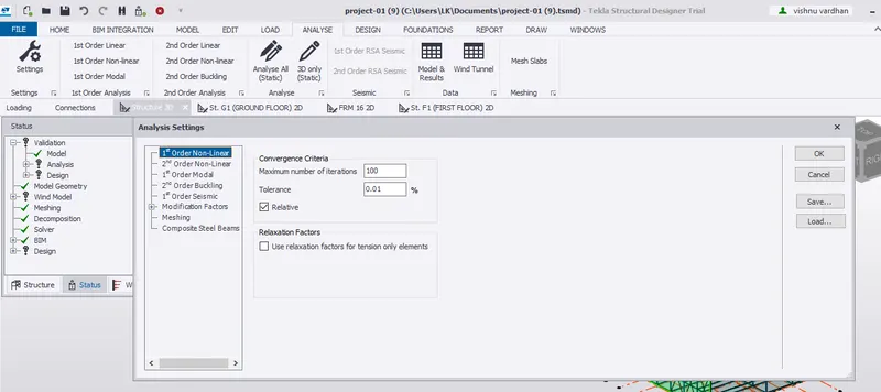
* Now let us select the 1st order linear option from the analysis a dialog box appears select the load cases and combinations required for the model and click ok.
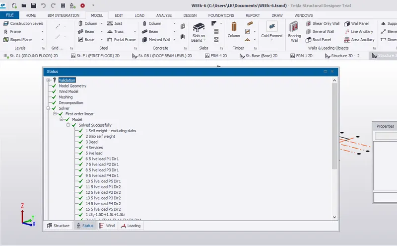
* now we can observe the analysis results in the project window check whether the model satisfies the load combinations if not modify the model.
19. finally let us foundation to the member we can do it by simply selecting pile base colum icon from foundation toolbar and simply by dragging the rectangular box arround the column the foundation is modeled
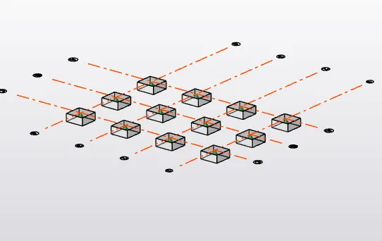
20 we can make use of properties tab to modify its properties.
RESULT:
we have successfully modeled the given plan in Tekla software from the plans
it begins from drawing construction levels, grids
Then we have modeled columns, beams,slabs etc acc to the plan
then we have applying loading to our member(dead load, live load as per IS CODE)
and wind load with the help of wind wizard icon
performed analysis of the model
final output
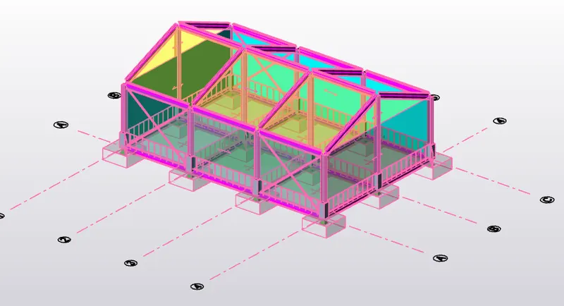
using scene content we can see the final model