Usage of Collaborate tool in REVIT
Q.1. Open an architectural template. Using the Manage tab set project base point and project shared coordinates for the project.
Ans=
Aim:- To set project Base-point and project shared coordinates
Introduction:-
The project base point can be used to establish a reference for measuring distances and positioning objects in relation to the model. Basepoint acts as a reference point for collaboration between different disciplines of a project and saves it as a central model file.
Procedure:-
Open Revit
On the home page click on new and select Imperial-Architectural Template
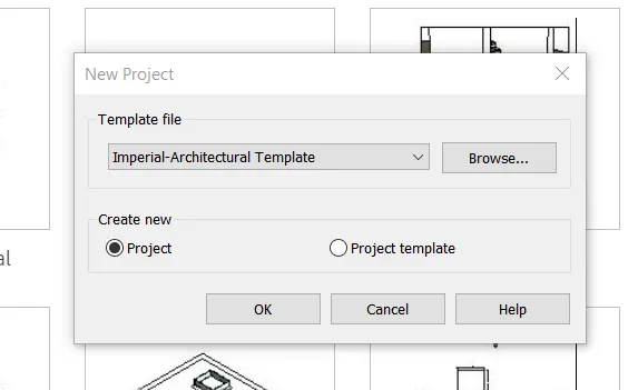
Step 1: Creating Base Point
Go to Architectural Tab
In the Datum panel click on GRID to draw grids
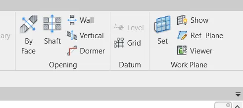
Draw one horizontal and one vertical grid
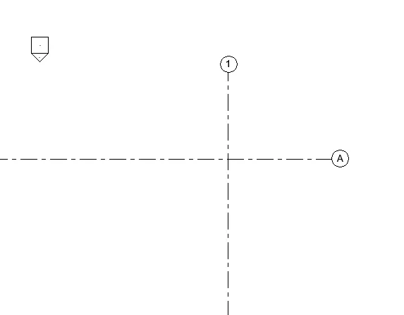
Step 2: Setting Project Coordinates
Go to the Manage tab
In Project location panel and click on Coordinates dropdown
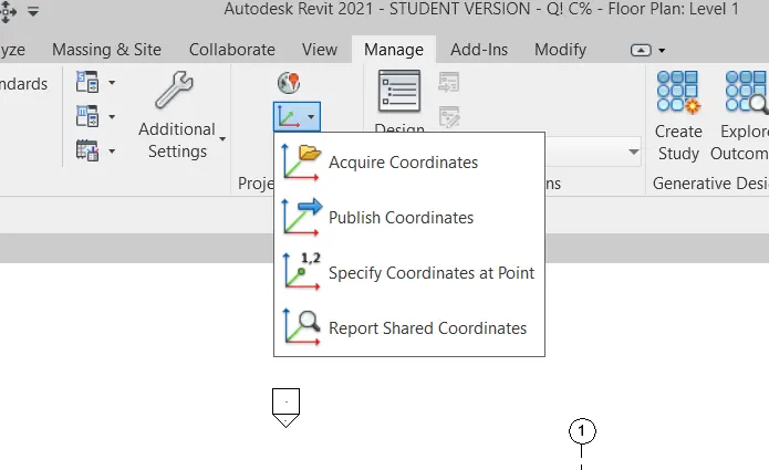
Click on Specify Coordinates at point
Click on the vertical gridline and set East/West as 0'0" as shown in the below figure
Click on the horizontal grid line and set North/South as 0'0" as shown in the below figure
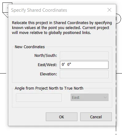
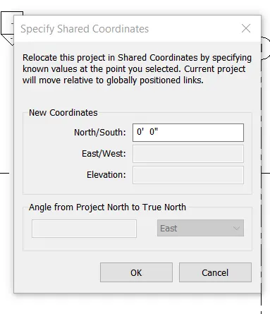
Result:-
Project coordinates have been created and collaboration tool is used to save the file as a central model file.
Q.2. Open another new file but with a structural template. Using the manage tab set project parameters the same as the architectural model. Copy the parameters from the architectural model to the structural template or enter the parameters manually into the structural model.
Ans=
Aim:- To create a structural template and set project parameters the same as the architectural model.
Introduction:-
The project base point can be used to establish a reference for measuring distances and positioning objects in relation to the model. Basepoint acts as a reference point for collaboration between different disciplines of a project and save it as a central model file.
Procedure:-
Open Revit
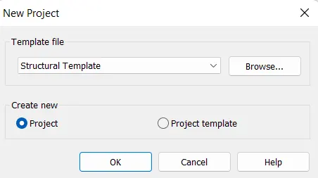
On the home page click on new and select Imperial-Structural Template
Step 1: Creating Base Point
Go to Structural Tab
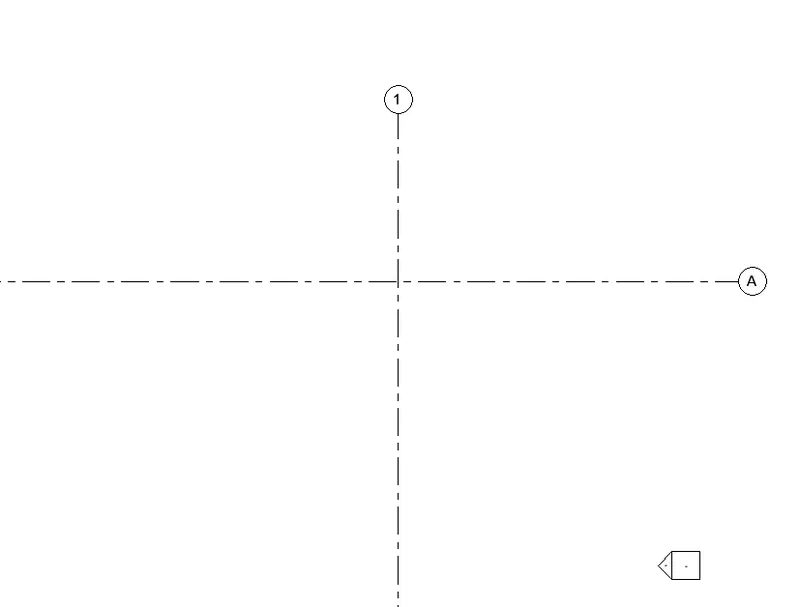
In the Datum panel click on GRID to draw grids
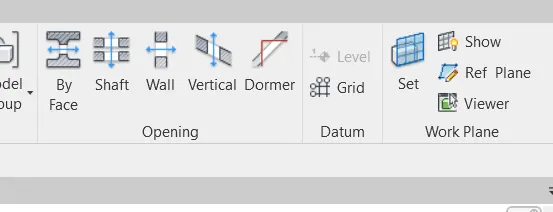
Draw one horizontal and one vertical grid
Step 2: Setting Project Coordinates
Go to the Manage tab
In the Project location panel and click on the Coordinates dropdown
Click on Specify Coordinates at point
Click on the vertical gridline and set East/West as 0'0" as shown in the below figure
Click on the horizontal grid line and set North/South as 0'0" as shown in the below figure
Step 3: Combined File
Open New Architectural Template as a combined
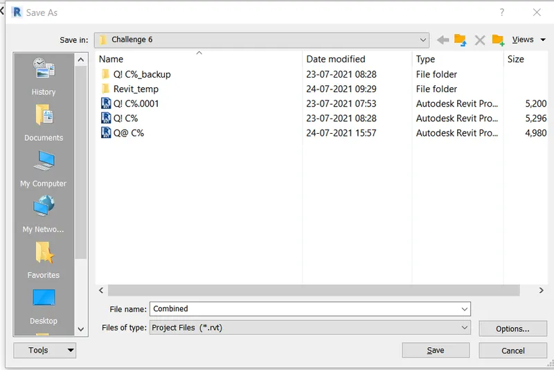
Step 4: Creating Shared coordinate
Go to the Insert tab and click on link Revit
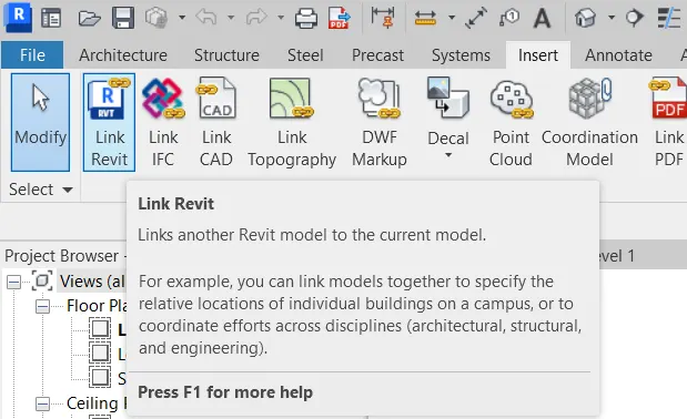
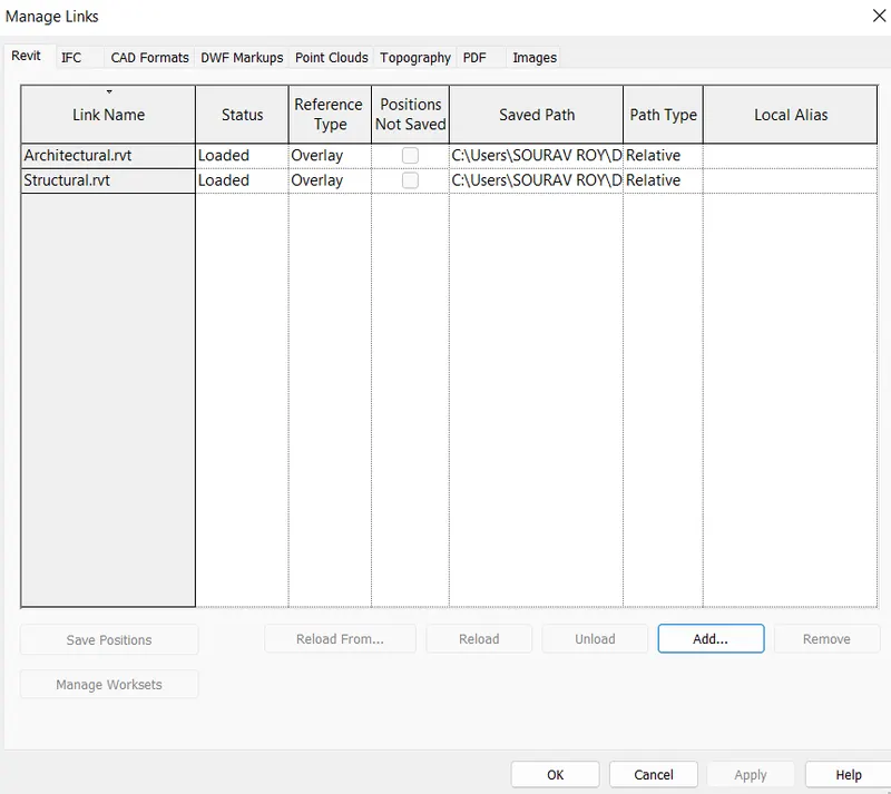
Add both files Architectural and Structural, and change it to attachment
Result:-
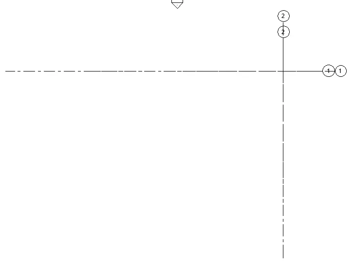
After adding links go to the manage tab, and click on relocate project by clicking on intersecting points
Q.3. Re-open the architectural model. Using the tools under the Collaborate tab make the architectural model a central model (enabling simultaneous working on the model).
Ans=
Aim:- To use collaborate tool and save it as a central model
Introduction:-
Revit provides several different ways to collaborate with team members who are also using the software. You can link multiple Revit models together, allowing team members to work in context. Through work sharing, users on the same local area network (LAN) can work together in the same Revit model.
Procedure:-
Open Revit
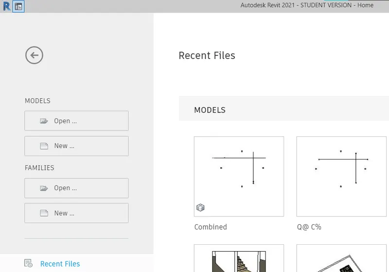
Click on Combined to open Arcitecutal Template from Question 1
Step 1: Using Collaborate Tool
Go to Collaborate Tab

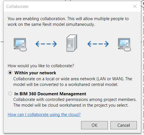
Click on 'Collaborate' from manage collaboration panel
Save file to continue
Click on "Within your Network"
Result:-
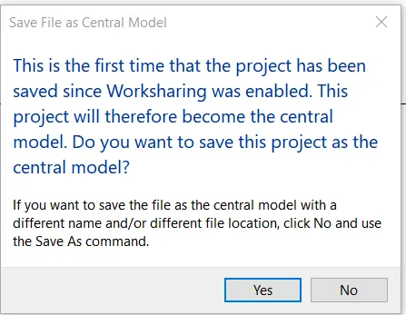
Save the file to save it as a central model
Q.4. Create the Grids Longitudinal and Transverse pattern for the project similar to the task done in Week 2.
Ans=
Aim:- Create the Grids Longitudinal and Transverse pattern for the project similar to the task done in Week 2.
Introduction:-
Use the Grid tool to place column grid lines in the building design. You can then add columns along the column grid lines. Gridlines are finite planes. You can drag their extents in elevation views so that they do not intersect level lines.
Procedure:-
Step 1: Opening Week 2 File
Open Revit
Click on 'Open' and open the Week 2 challenge
Step 2: Creating Grids
Go to Architectural Tab
In the Datum panel click on GRID to draw grids
Draw horizontal and vertical grids at column points
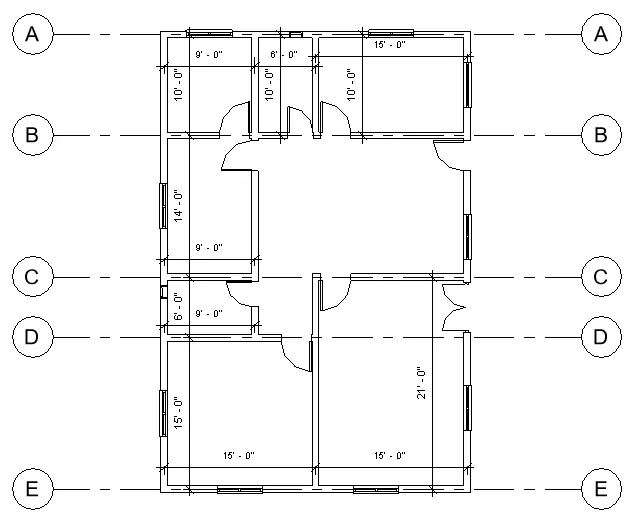
Set Horizontal grid names from Top to bottom and in Alphabets as shown in below figure
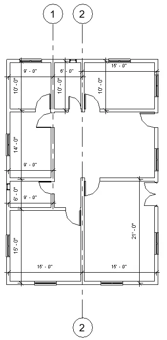
Set Vertical grid names from Right to left and in numerical as shown in the below figure
Result:-
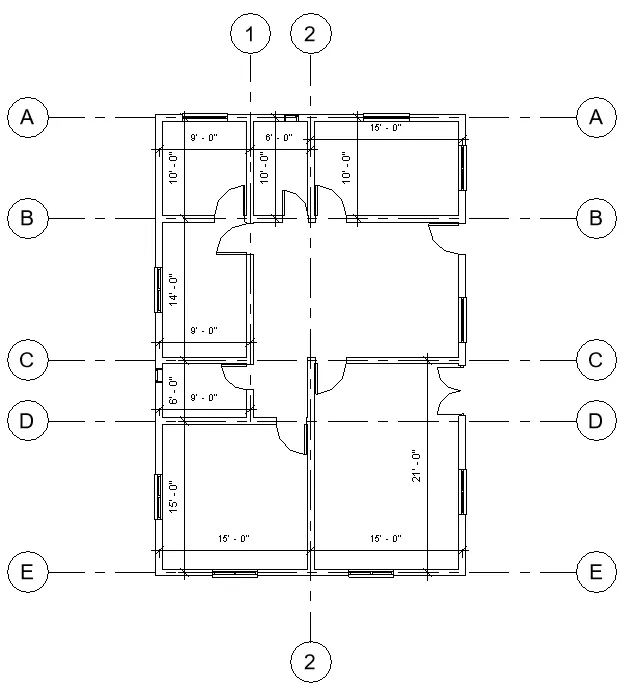
The final end result of both Horizontal and Vertical grids is as follows
Q.5. Synchronize the changes from the local copy to the central file of the architectural model.
Ans=
Aim:- To Synchronize the changes from the local copy to the central file of the architectural model.
Introduction:-
Synchronizing the local copy file to the central file will bring changes done to the model in local copy to a central file where
Procedure:-
Step 1: Opening Architectural File
Open Revit
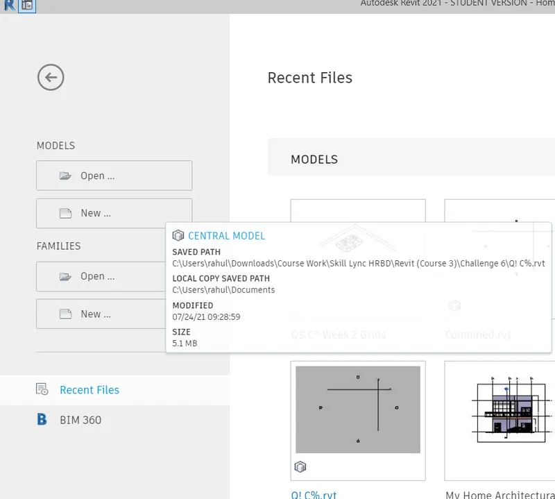
Click on the 'Architectural' file
Step 2: Synchronizing with central file
Go to Collaborate tab
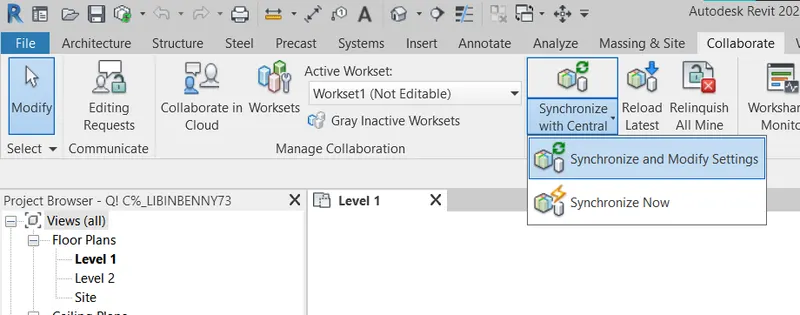
From the Popup click on browse to select a combined file
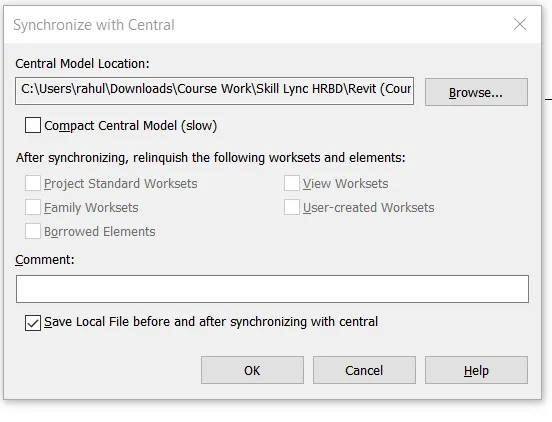
Click ok to save to central file
Result:-
The model is saved as a central file
Q.6. Open the structural model and use the collaborate tools to save the model as a central file.
Ans=
Aim:- To Synchronize the changes from the local copy to the central file of the structural model.
Introduction:-
Synchronizing the local copy file to the central file will bring changes done to the model in local copy to a central file where
Procedure:-
Step 1: Opening Structural File
Open Revit
Click on the 'Structural' file
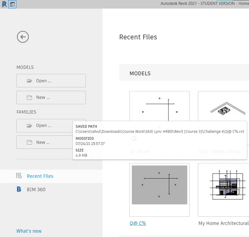
Step 2: Synchronizing with central file
Go to Collaborate tab
From the Popup click on browse to select a combined file
Click ok to save to central file
Result:-
The model is saved as a central file.
Q.7. Under the Collaborate tab, select the grids and levels from the architectural model, and using Copy Monitor try to copy the grids to the structural model. See what happens when the copy monitored grid is moved around in the structural model.
Ans=
Aim:- To use copy monitor to copy the grids and paste them into the structural model.
Introduction:-
Copy/Monitor is used primarily to copy information from one model to another. This can for example be used by a structural designer at the beginning of their project to transfer all levels, grids and walls from an Architecture model to a Structural model.
Procedure:-
Step 1: Opening Architectural File
Open Revit
Click on the Architectural Template file
Step 2: Drawing Grids
Go to Architectural Tab
In the Datum panel click on 'grid' and add some horizontal and vertical grids as shown below
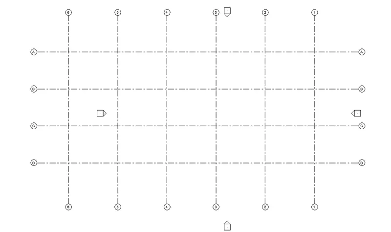
Step 3: Opening structural file
Open New Structural Template file
Go to the Manage tab and click on manage link.
Click on add to add the architectural drawing to the file
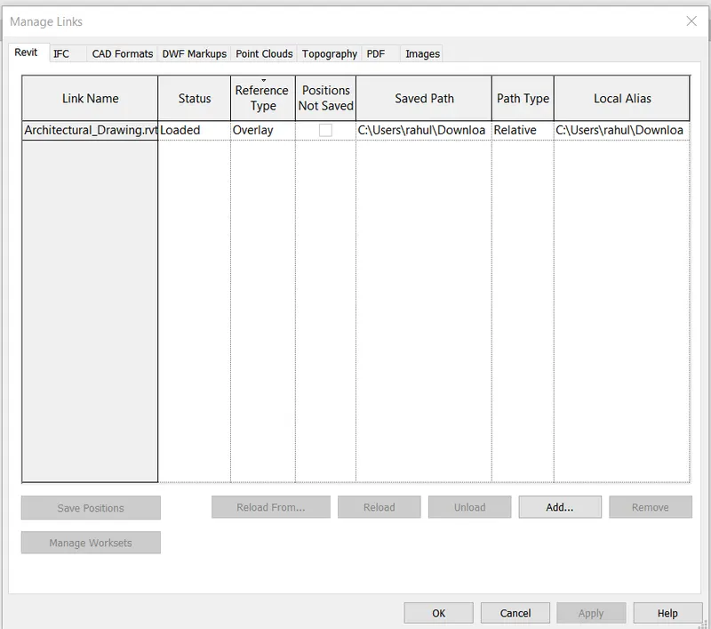
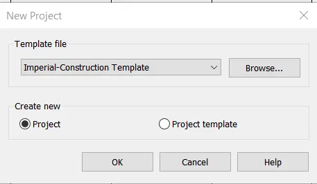
Click ok to add it construction Template
Step 4: Using Copy Monitor
Go to collaborate Tab and click on copy monitor and click on the select link
Click on the added link in the last step
Click on copy to create a copy of selected files
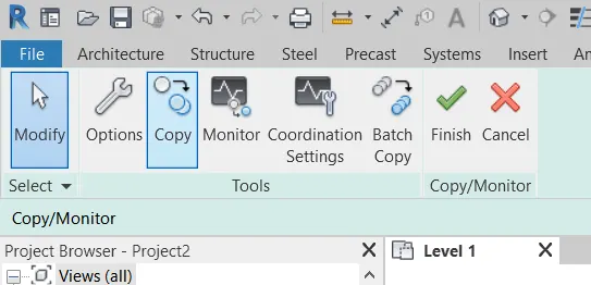
Select all the grids to copy them to the Structural Model
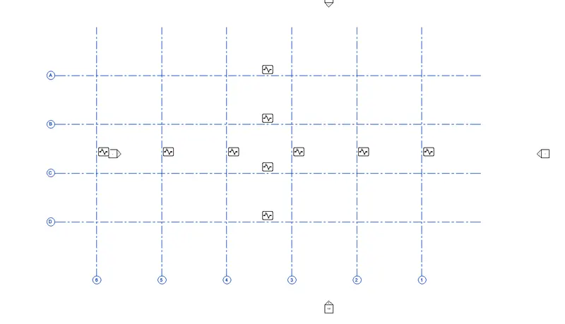
Result:-
The final result after using copy grids using copy monitor is as follows.
Q.8. Create another new file with a construction template. Save the new file as a central model. This file will include both architectural and structural model. Under the manage tab, Click manage links to link both architectural and structural files. Save the file and close all the files.
Ans=
Aim:- To use a copy monitor to copy the grids and paste them into the structural model.
Introduction:-
The Manage Links dialog has tabs for Revit models, IFC links, CAD Formats, DWF Markups, Point Clouds, and Topography. Under the tabs are columns that provide information about the link. The Manage Links dialog has tabs for Revit models, IFC links, CAD Formats, DWF Markups, and Topography.
Procedure:-
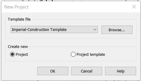
Step 1: Opening Construction File
Open Revit
Click on the New tab and open the New Construction Template file
Step 2: Adding Links
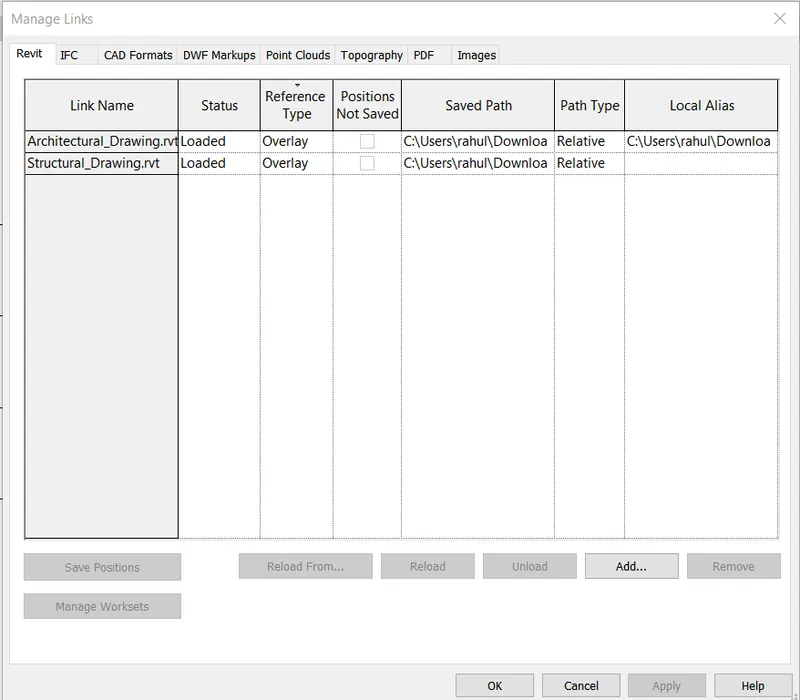
Go to the Manage tab and click on manage kink
Click on add to add the architectural drawing to the file with shared coordinates
Click on add again to add the structural drawing to the file with shared coordinates
Result:-
The end result of adding both architectural and structural links is shown below
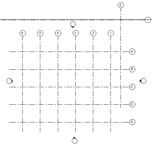
Q.9. Are the grids from structural and architectural model matching in the construction template created? If yes the model is set up for project 2. If not work on the shared parameters and linking options under Manage links
( Hint: origin to origin, by shared coordinates or by project base point to base point ) to link the models in an appropriate manner.
Ans=
Aim:- To Adjust the model in Question 8
Introduction:-
The Manage Links dialog has tabs for Revit models, IFC links, CAD Formats, DWF Markups, Point Clouds, and Topography. Under the tabs are columns that provide information about the link. The Manage Links dialog has tabs for Revit models, IFC links, CAD Formats, DWF Markups, and Topography.
Procedure:-
Step 1: Opening File
Open Revit
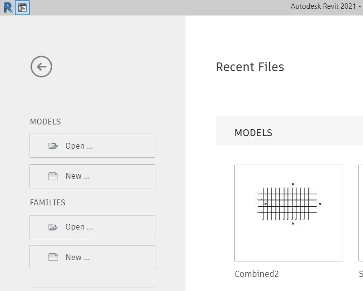
Click on the combined-2 file on the home page
Step 2: Checking
The file created does match both grids
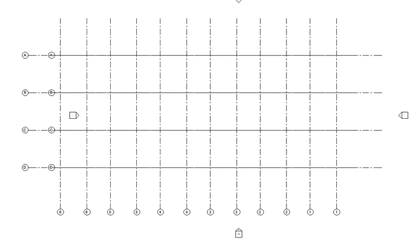
Step 3: Adjusting Links
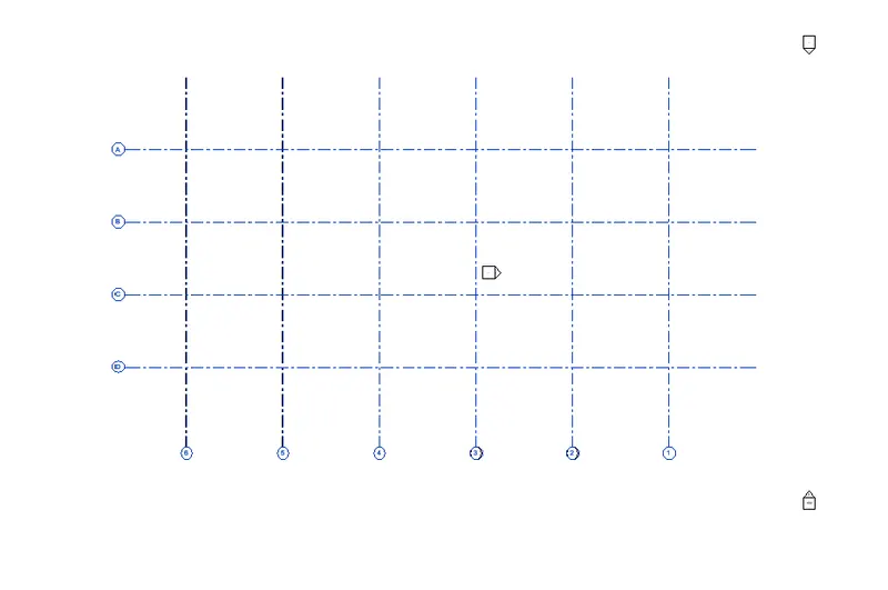
Go to the Manage tab and click on relocate the project to adjust the project
Result:-
The end model after adjusting is as follows
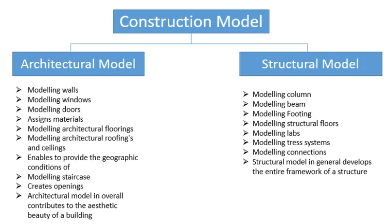
Q.10. List a flow chart of a project tree set up in terms of Construction model, Architecture & Structure model, in this exercise and understand how many people can work on the same project using Revit simultaneously.
Ans=
In very general terms, a model is a representation, often three-dimensional, of a structured system or procedure. It can represent something that already exists, or maybe a model that it is intended will be adopted or followed.
A building, such as an architectural model is a type of model (often to scale) built to develop or represent aspects of a design or to communicate design ideas. Historically, such models have been physical representations, made from materials such as paper, cardboard, timber, and so on. These can be used to help explain proposals to clients, planning officers, members of the public, and other stakeholders, or they can be used as tools to help designers explore complicated three-dimensional aspects of a design.
The flow chart for the Construction model as per architectural and structural models is as follows
Use work-sharing to allow multiple users to work on different parts of one Revit project.
Work-sharing allows simultaneous access to a shared model through the use of a central model. Use work-sharing when you are working with a single model (one RVT file) that will have multiple team members working on it.
Using linked models, project elements or systems are separated into individually managed models that can be linked together. Use linked models when your project contains distinct buildings, such as a campus, or when you are working with team members from other disciplines, such as:
- structural engineers
- mechanical engineers
- architects
You can also use work-sharing in linked models.