Usage of Collaborate tool in REVIT
1)
Aim: To open an architectural template and use the Manage tab to set the project base point and project shared coordinates.
Procedure:
Step 1: Open a new architectural template and save it at an appropriate location.
Step 2: Now click on Grid tools from the Architectural tab and draw a horizontal and a vertical grid as shown below.
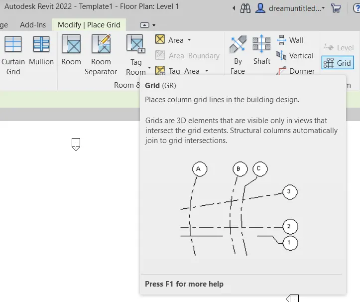
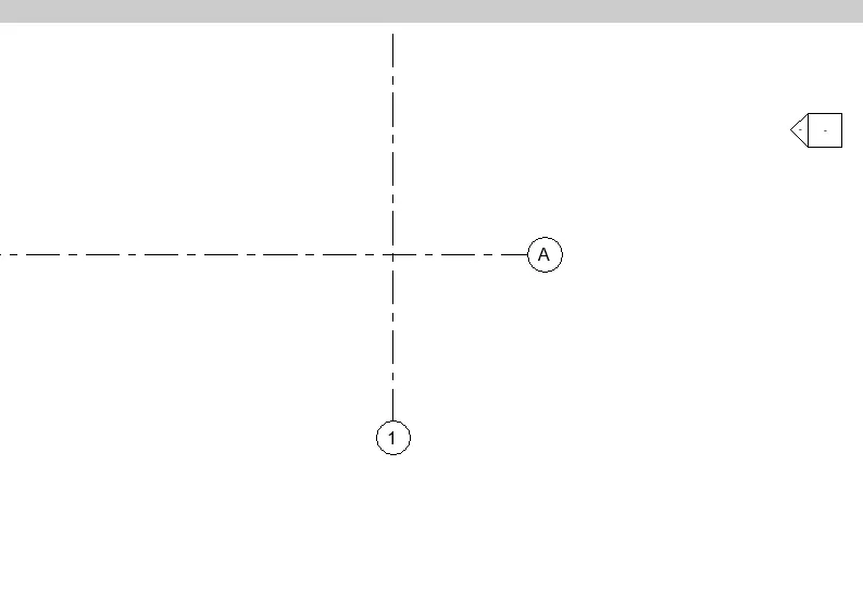
Step 3: Now click on Manage Tool and select the Coordinates icon and click on "Specify Coordinates at Point".
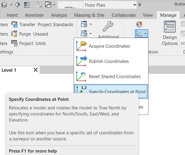
Step 4: Now specify coordinates for both grids and set coordinates to 0' 0" as shown below:
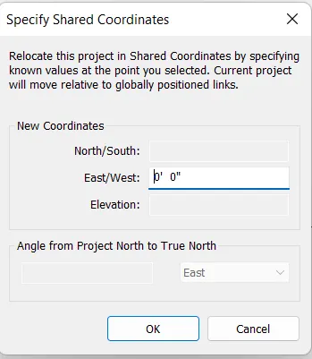
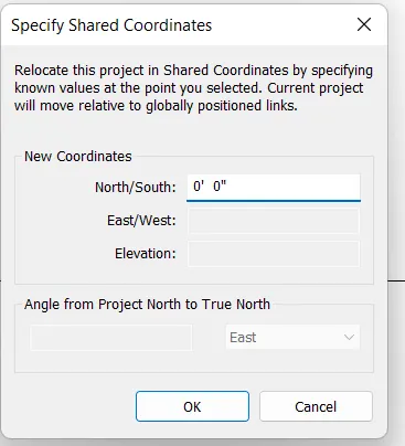
Result: Project base point and project shared coordinates are set for an architectural template.
2)
Aim: To open another new file but with a structural template. Using the manage tab set project parameters the same as the architectural model. Copy the parameters from the architectural model to the structural template or enter the parameters manually into the structural model
Procedure:
Step 1: Open a new Structural template and save it at an appropriate location.
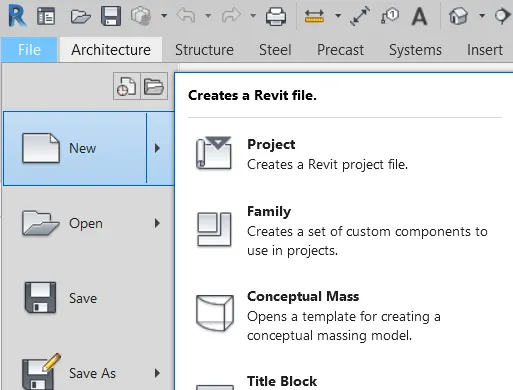
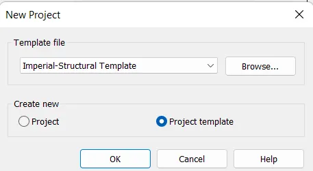
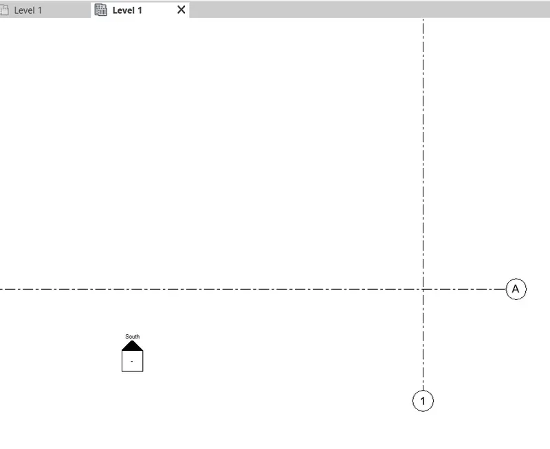
Step 2: Now click on Grid tools from the Structural tab and draw a horizontal and a vertical grid as shown below.
Step 3: Now click on Manage Tool and select the Coordinates icon and click on "Specify Coordinates at Point".
Step 4: Now specify coordinates for both grids and set coordinates to 0' 0" as shown below:
Result: Project base point and project shared coordinates are set for a structural template.
3)
Aim: Re-open the architectural model. Using the tools under the Collaborate tab makes the architectural model a central model (enabling simultaneous working on the model)
Procedure:
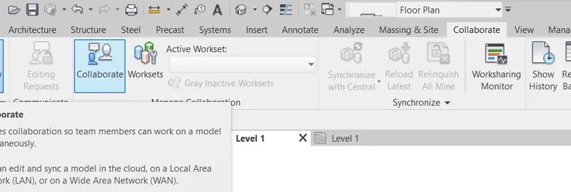
Step 1: Open the architectural file saved first and go to collaborate tab and click on collaborate option.
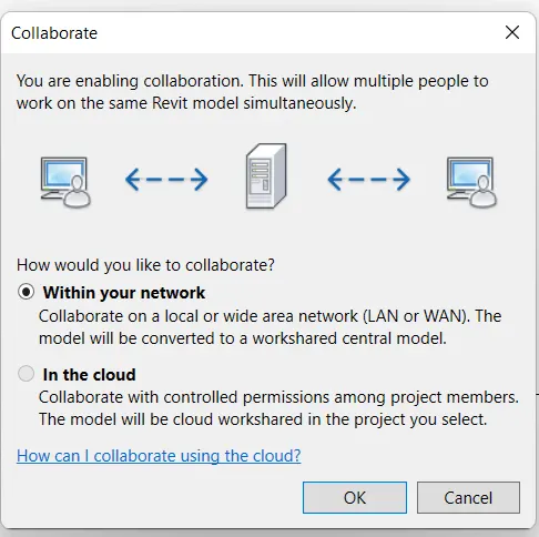
Step 2: A dialogue box will pop up. Select Within your network option for security reasons, as we are working on the same Local Area Network. Click OK.
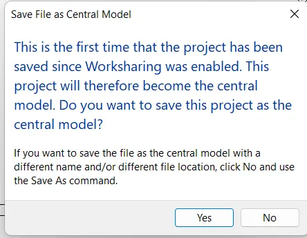
Step 3: Now save the file. This file is saved the first time after collaboration so it will ask to keep it as a central model. click Yes.
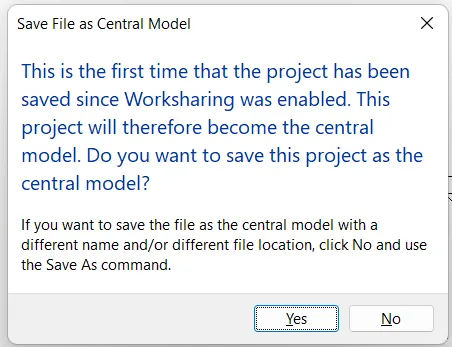
Result: Architectural project file is saved as a Central model for collaboration.
4)
Aim: To create the Grids Longitudinal and Transverse pattern for the project similar to the task done in Week 2.
Procedure:
Step 1: Open the architectural file saved earlier. Under the architectural tab select grid.
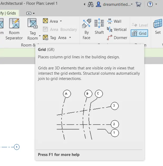
Step 2: Select previously drawn grids and pin them so that their coordinates won't change.
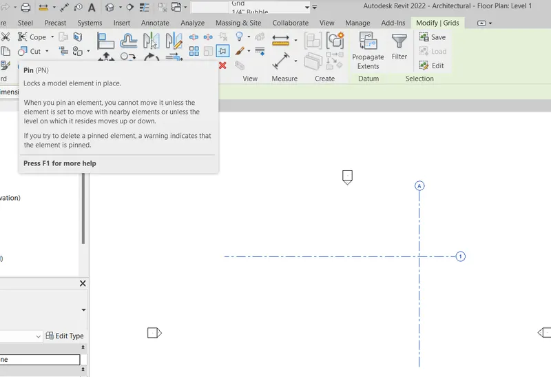
Step 3: Create a grid system having a 20 ft distance apart.
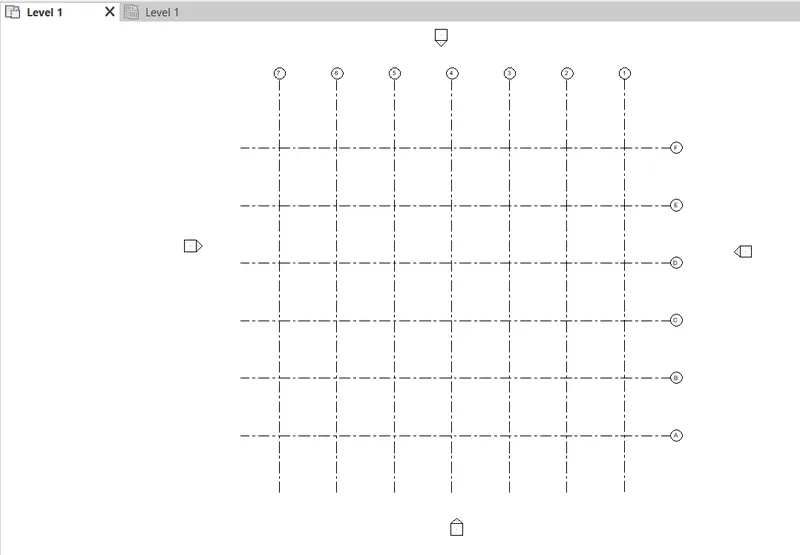
Result: A Grid system of longitudinal and transverse grids is created.
5)
Aim: To synchronize the changes from the local copy to the central file of the architectural model.
Procedure:
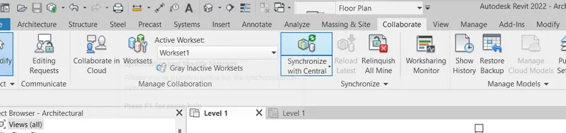
Step 1: From Collaborate tab select Synchronize with Central for synchronizing the changes made in architectural templates. in our case grid system is created.
Step 2: Click on synchronize and modify settings.
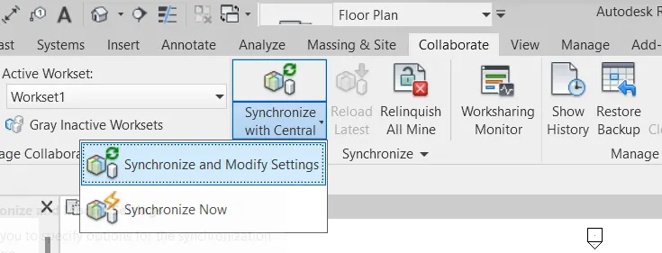
Step 3: A dialogue box will pop up. Click OK.
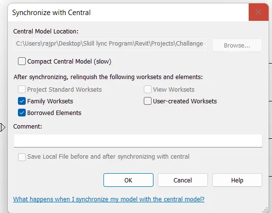
Result: Architectural template is synchronized changes from its local copy.
6)
Aim: To open the structural model and use the collaborate tools to save the model as a central file.
Procedure:
Step 1: Open the Structural file saved first and go to collaborate tab and click on collaborate option.
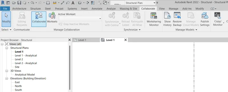
Step 2: A dialogue box will pop up. Select Within your network option for security reasons, as we are working on the same Local Area Network. Click OK.
Step 3: Now save the file. This file is saved the first time after collaboration so it will ask to keep it as a central model. click Yes.
Result: Structural project file is saved as a Central model for collaboration.
7)
Aim: Under the Collaborate tab, select the grids and levels from the architectural model, and using Copy Monitor try to copy the grids to the structural model. See what happens when the copy monitored grid is moved around in the structural model
Procedure:
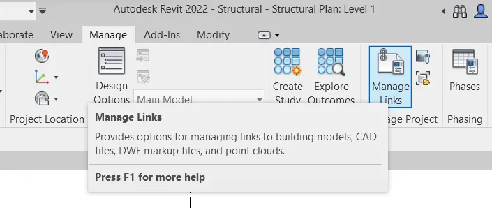
Step 1: Open the structural project file saved first. Now from the Manage tab, click on the manage link and click on add.
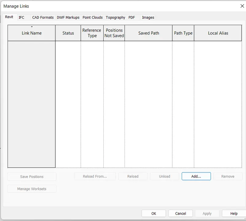
Step 3: Select the Architectural file and add this link using auto shared coordinate as shown below:
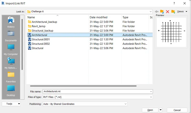
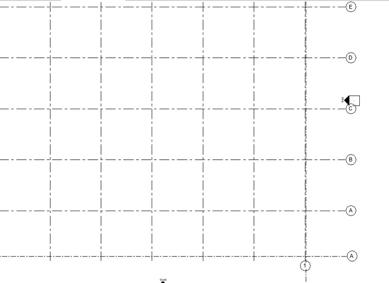
Step 4: Click on OK. Grids link will be loaded in the structural project but it is not overlapped properly even after assigning 0' 0" coordinates.
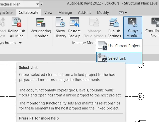
Step 5: Now click on the Copy/Monitor option from Collaborate tab and click on the select link. Now select grid link with structural project.
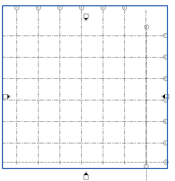
Step 6: Now click on Copy and check the Multiple and select all grids and click on Finish. Now Grids will be overlapped properly.
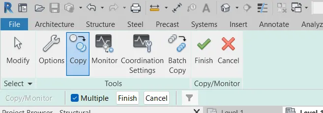
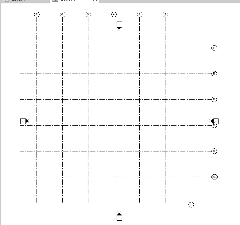
Result: Grids are linked and copied from the Architectural project using Copy Monitor to the structural model.
8)
Aim: To create another new file with a construction template. Save the new file as a central model. This file will include both architectural and structural models. Under the manage tab, Click manage links to link both architectural and structural files. Save the file and close all the files.
Procedure:
Step 1: Create a new file with a construction template and save at appropriate location.
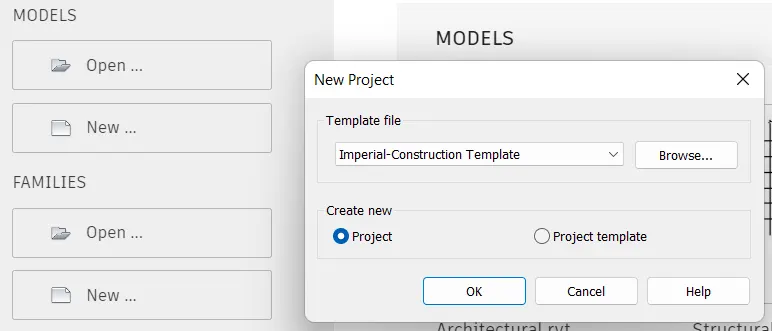
Step 2: Under the collaborate tab, click on collaborate and select within the network.
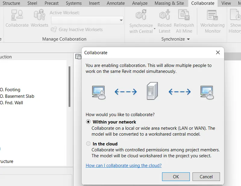
Step 3: Now save the file again as a central file.
Step 4: Now from the Manage tab, select on the manage link option and click on Add option. Select the Architectural and structural files saved earlier.
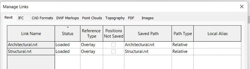
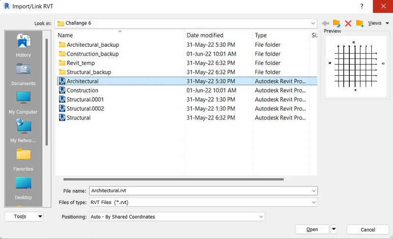
Step 5: Click on OK. Both files will be linked to the construction central file. Now save the file and close all files.
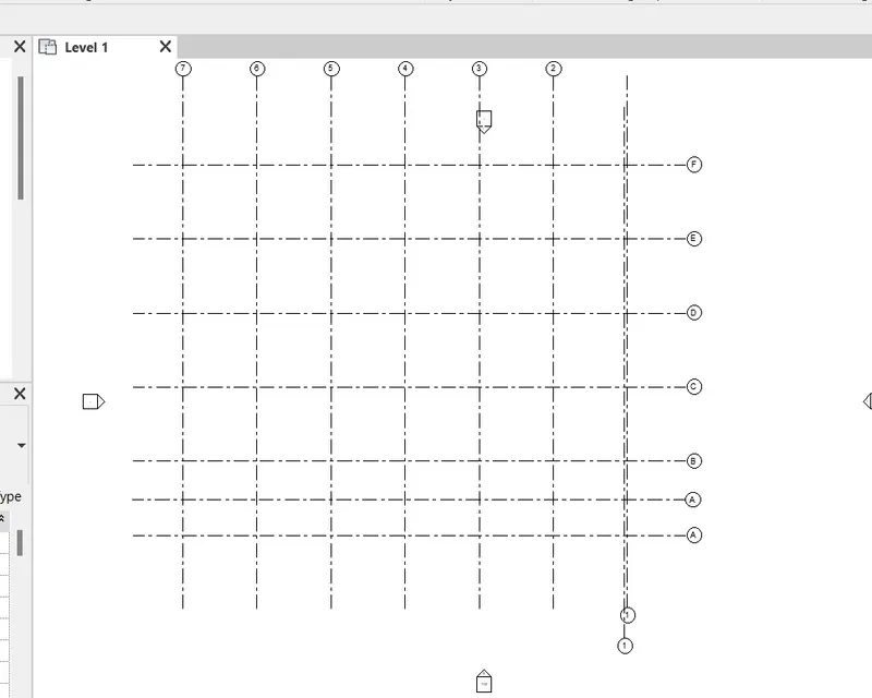
Result: Both Architectural and Structural files are linked to the Construction central file using the manage links option.
9)
Aim: Since the grids from both structural and architectural files are not matching properly, so we need to change parameter settings so that they can match.
Procedure:
Step 1: Open the construction project file. Click on any link (architectural or structural).
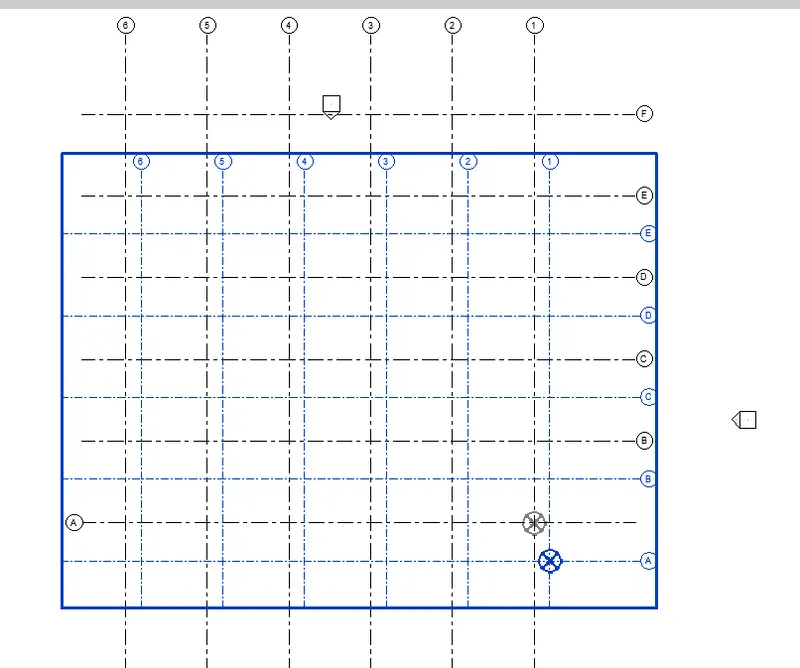
Step 2: Now under Modify tab select the move option and specify a base point and move it in such a way that both grids coincide.
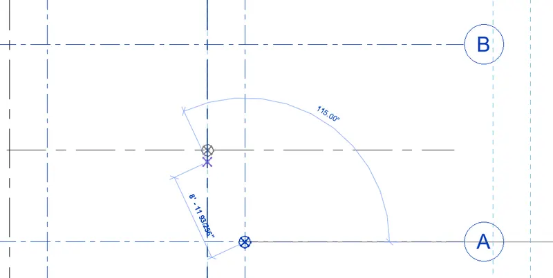
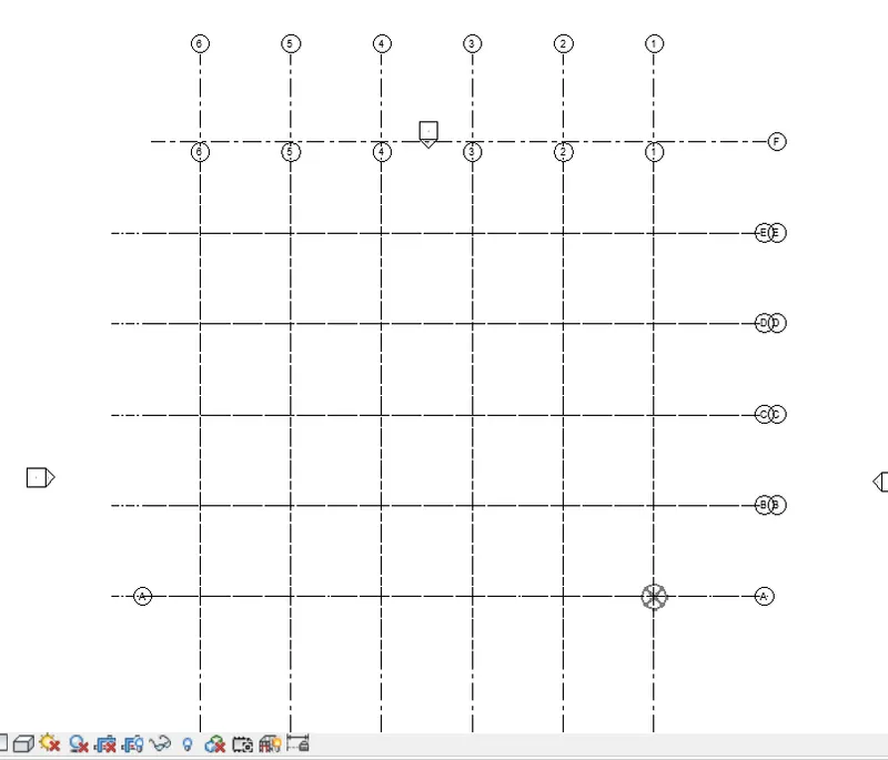
Step 3: Now from the Manage tab, specify coordinates to base grids as shown below:
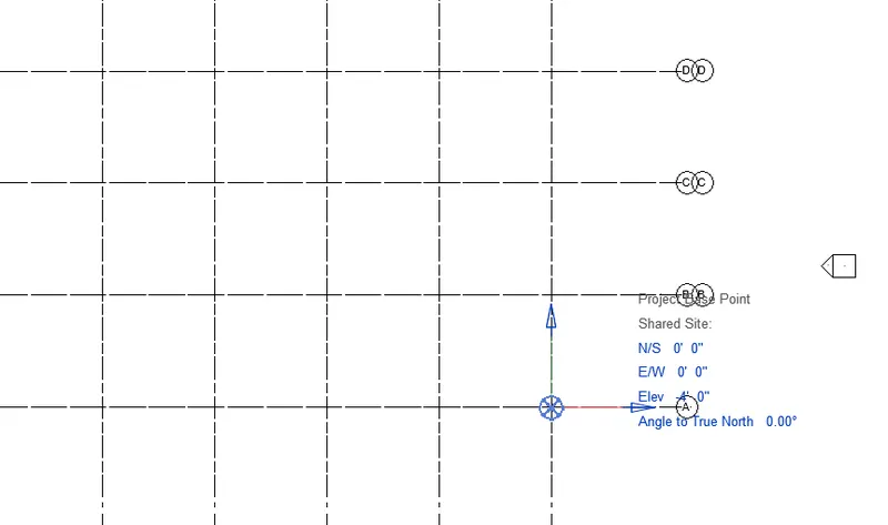
Result: Grid systems are matched perfectly.
10)
Aim: To create a flow chart of a project tree set up in terms of the Construction model, Architecture & Structure model, in this exercise and understand how many people can work on the same project using Revit simultaneously.
Procedure:
In this project, we have worked on two types of models, the Architecture and Structure models. Many people can work simultaneously on these two domains by creating multiple elements and designing various components as shown in the flow chart.
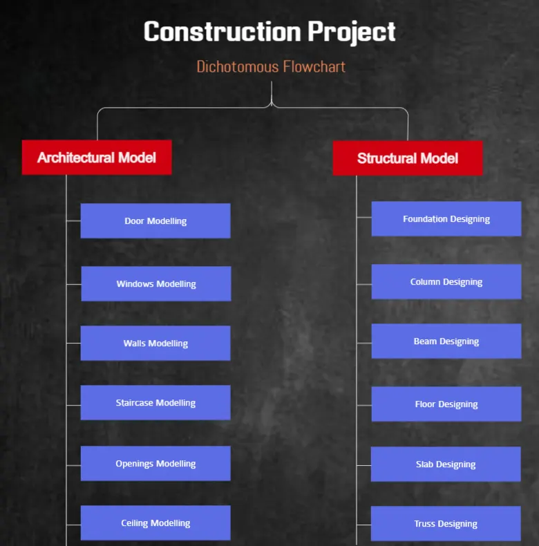
Result: A flow chart is created explaining how many people can work on the same project using Revit simultaneously.