Usage of Collaborate tool in REVIT
1. AIM
To set project base point and project shared coordinates for the project using manage tab in the architectural template.
INTRODUCTION
- The project base point can be used to establish a reference for measuring distances and positioning objects in relation to the model
- Initially, in stock templates, it identifies the origin (0,0,0) of the project coordinate system. Use the project base point as a reference point for measurements across the site.
- When you combine multiple models and files in a single project, use share coordinates to establish the positions of the files in relation to each other.
- A Revit project has internal coordinates for all the elements that compose the model in a project. Those coordinates are known to this project only
- This is sufficient if you have a standalone model whose position is not relevant to other models or to a site.
- However, if you want the position of the model to be known to other linked models. you need to share coordinates.
- Use the Shared Coordinate tools to establish the relative positions of the different files and ensure that those relationships are maintained
- To establish a common coordinate position and then share that position between files, use the Acquire Coordinates tool or the Publish Coordinates tool.
PROCEDURE
STEP-1
- First, we have to open the Revit.
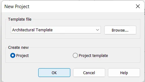
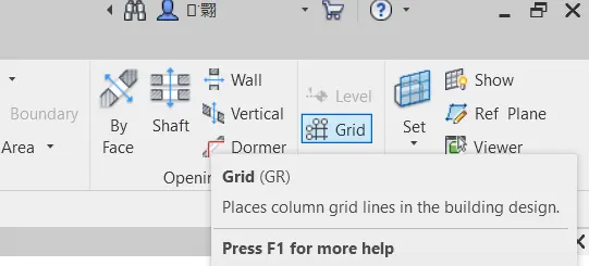
- Next create a project using the architectural template. Next draw the horizontal and vertical grid, intersecting each other And give name for horizontal grid as 2
- Next the name for vertical grid as 1
STEP-2
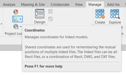
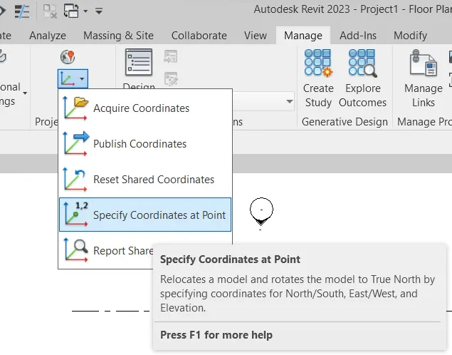
- Next, we coordinate option in the manage tab, and select the specify coordinates at point option and click on the horizontal grid.
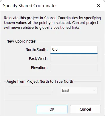
- After selecting the horizontal grid, the specify shared coordinates tab will appears.in the specify shared coordinates tab we need to enter the coordinates for north/south as 0-0, as shown in the below figure.
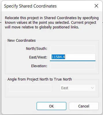
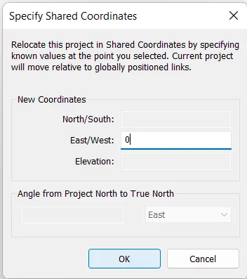
STEP-3
- Next, we coordinate option in the manage tab, and select the specify coordinates at point option and click on the vertical grid
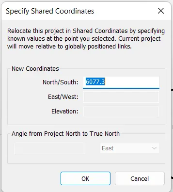
- After selecting the vertical grid, the specify shared coordinates tab will appears. in the specity shared coordinates tab we need to enter the coordinates for east/west as 0'-0", as shown in the below figure
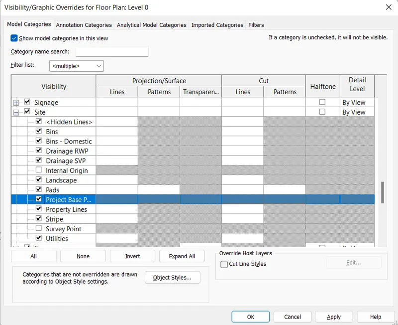
STEP-4
- Next, we have to save the project as Architectural, as shown below.
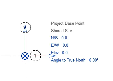
RESULT
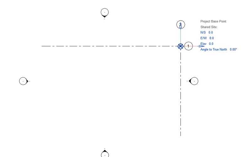
Using the Manage tab the project base point and project shared coordinates have been setup successfully for the project in the architectural template.
2. AIM
To set project base point and project shared coordinates for the project using manage tab in the structural template
INTRODUCTION
- The project base point can be used to establish a reference for measuring distances and positioning objects in relation to the model initially, in stock templates, it identifies the origin (0.0.0) of the project coordinate system.
- Use project base point as a reference point for measurements across the site.
- When you combine multiple models and files in a single project, use shared coordinates to establish the positions of the files in relation to each other.
- A Revit project has internal coordinates for all the elements that compose the model in a project. Those coordinates are knowing to this project only
- This is sufficient if you have a standalone model whose position is not relevant to other models or to a site
- However, if you want the position of the model to be known to other linked models. you need to share coordinates Use the Shared Coordinate tools to establish the relative positions of the different files and ensure that those relationships are maintained
- To establish a common coordinate position and then share that position between files, use the Acquire Coordinates tool of the Publish Coordinates tool
PROCEDURE
STEP-1
- First, we have to open the Revit
- Next create a project using the structural template
- Next draw the horizontal and vertical gad, intersecting each other.
- And give rate for horizontal grid A.
- Next give the name for vertical grid as 1
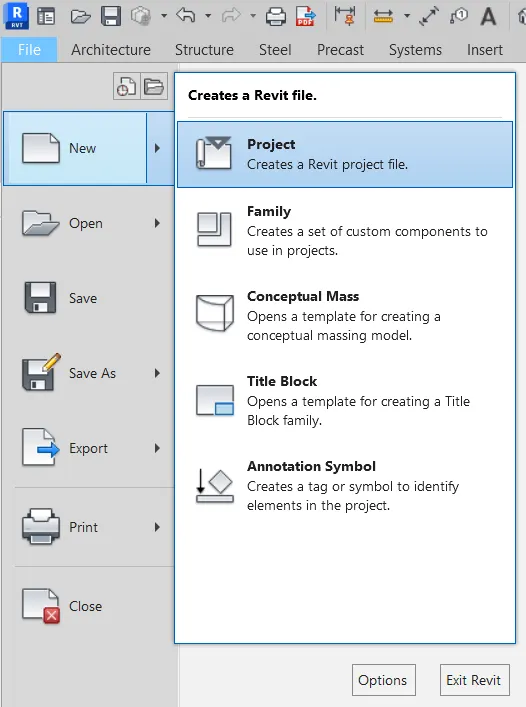
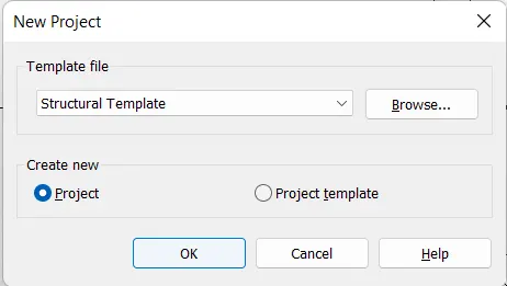
STEP-2
- Next, we coordinate option in the manage tab, and select the specify coordinates at point option and click on the horizontal grid.
- After selecting the horizontal grid. the specify shared coordinates tab will appears.
- in the specify shared coordinates tab we need to enter the coordinates for north/south as O. as shown in the below figure
STEP-3
- Next, we coordinate option in the manage tab, and select the specify coordinates at point option and click on the vertical grid.
- After selecting the vertical grid, the specify shared coordinates tab will appears in the specify shared coordinates tab we need to enter the coordinates for east/west as O as shown in the below figure.
STEP-4
- Next we have to save the project as projects structural, as shown below.
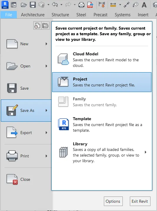
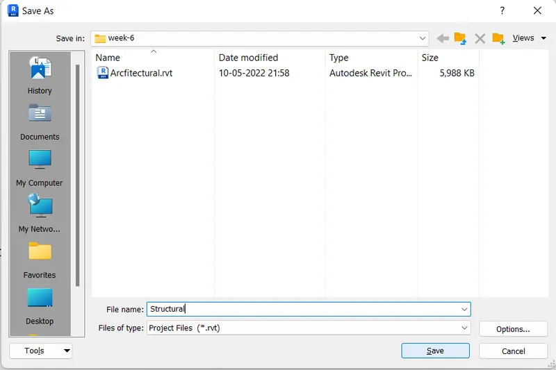
RESULT
Using the Manage tab the project base point and project shared coordinates have been setup successfully for the project in the structural template.
3. AIM
To make the architectural model as a central model using the collaborate tab
INTRODUCTION
- With server-based work-sharing some of the tasks to manage the central model require a different approach than file-based work-sharing
- The central model is the master project file for a workshare project.
- The central model stores the current ownership information for all elements in the project, and acts as the distribution point for all changes published to the file.
- All team members save their own local couples of the central model, work locally, and then use the Synchronize with Central command to synchronize their edits to the model with the central model
PROCEDURE
STEP-1
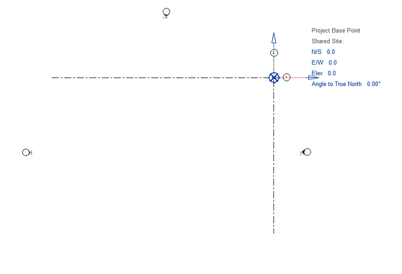
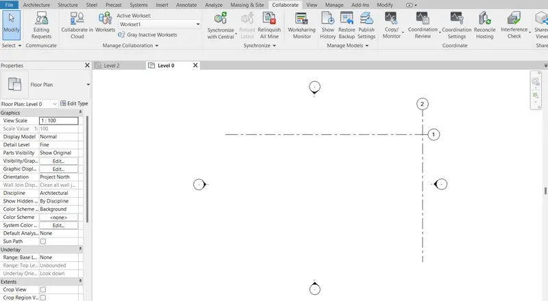
- First open the Revit, and draw the vertical and horizontal grids as shown below.
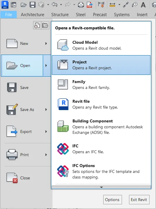
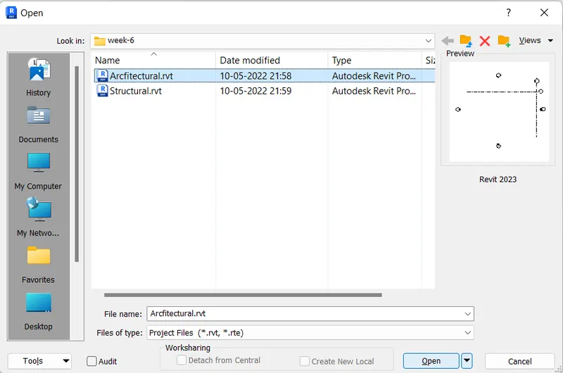
STEP-2
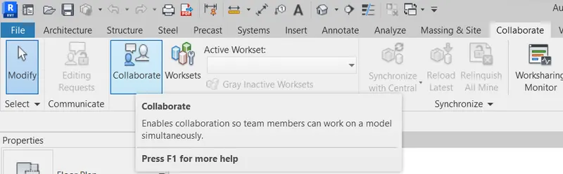
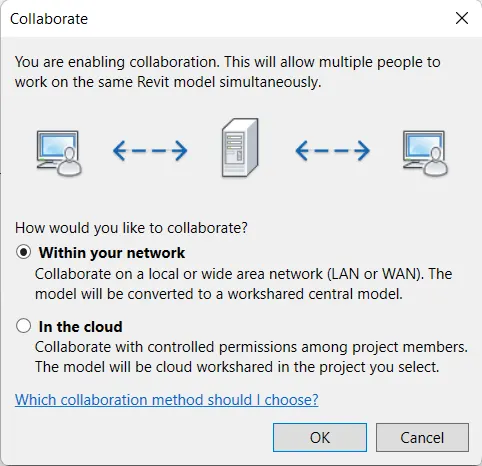
- Next click on the collaborate tab, then the new tab will be visible
- Then click on the ok button.
STEP-3
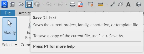
- Next, we see another tab, and select save model and continue option, as shown below.
STEP-4
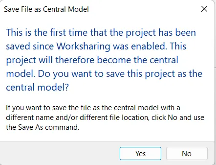
- Next, we save the project as project, shown below.
STEP-5
- Next we save the project file as a central model as shown below.
RESULT
Created an architectural model as a central model using the collaborate tab
4. AIM
To create the Grids Longitudinal and Transverse pattern for the project similar to the task done in Week 2
INTRODUCTION
- Grid lines are finite planes, we can drag their extents in elevation views so that they do not intersect level lines. This allows you to determine whether grid lines appear in each new plan view that you create for a project.
- Grids can be straight lines, arcs or multi-segmented. You can hide grid lines atter you add them
- Use the Grid tool to place column grid lines in the building design. We can then add columns along the column grid lines.
- As we start to construct our 3D model, we need some method of controlling the vertical height of our elements-be it floor heights the base and top of columns window all heights, etc.
- This is where Levels come into play. in order to create an effective and efficient model it is crucial that you understand the use of Levels. The correct use of Levels will ensure that your model can readily be adjusted with the minimum of effort.
PROCEDURE
STEP-1
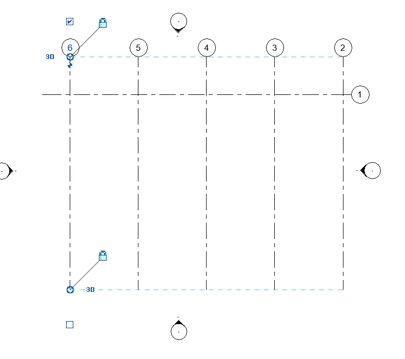
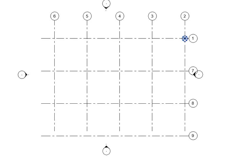
- First, we create the vertical grids, as shown below.
STEP-2
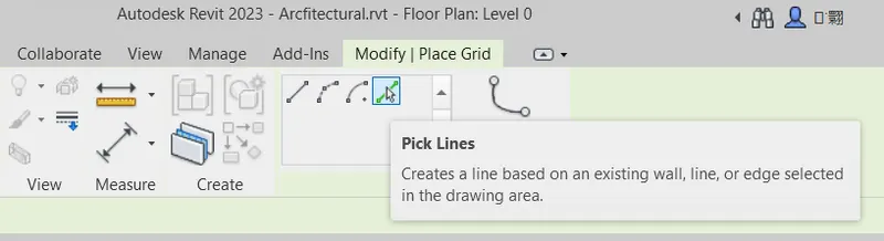
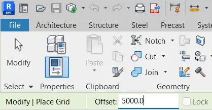
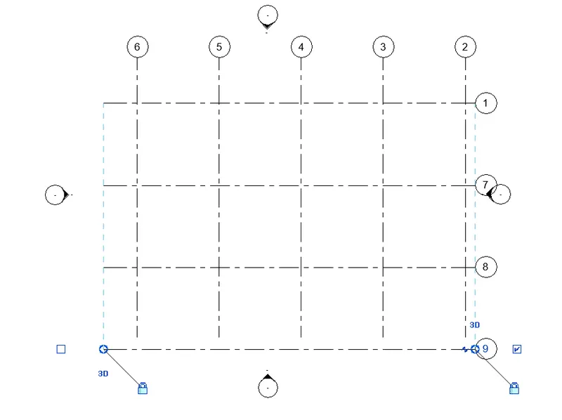
- Next horizontal grids are created.
STEP-3
- The vertical and horizontal grids are created successfully.
RESULT
Created the grids longitudinal and transverse pattern for the project similar to the task done in week 2
5. AIM
To synchronize the changes from the local copy to the central file of the model architectural
INTRODUCTION
- The Synchronize with Central process loads changes from other files to the central file, and then saves local changes to the central file, which are saved by default
- The Central File Access pane of Work-sharing Monitor displays the progress of the Synchronize with Central operation, which involves several distinct steps.
PROCEDURE
STEP-1
- First, we have to collaborate using the collaborate toolbar.
- Next, we have to save the project as central model.
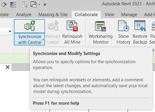
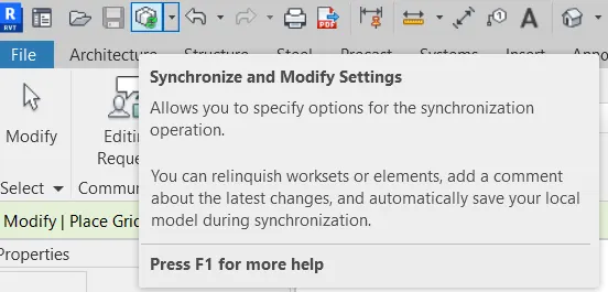
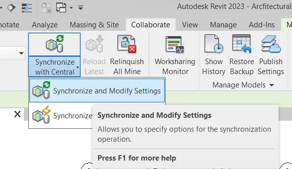
- Next the synchronize option will be visible, as shown below.
STEP-2
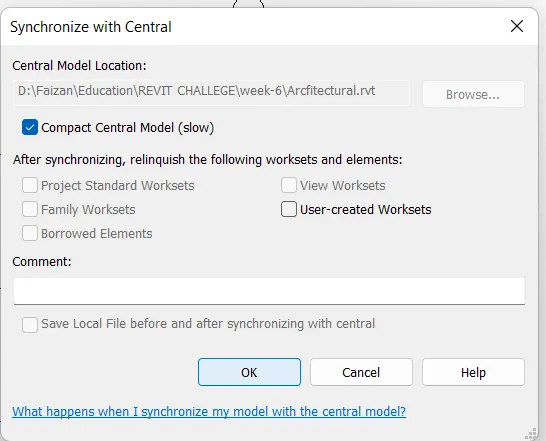
- After selecting the synchronize option, a new tab appears.
RESULT
Synchronized the changes from the local copy to the central file of the architectural model.
6. AIM
To save the model as a central file using the collaborate tool in the structural model.
INTRODUCTION
- With server-based work sharing, some of the tasks to manage the central model require a different approach than file-based work sharing
- The central model is the master project file for a workshare project
- The central model stores the current ownership information for all elements in the project, and acts as the distribution point for all changes published to the file
- All team members save their own local copies of the central model, work locally. and then use the Synchronize with central command to synchronize their edits to the model with the central model.
PROCEDURE
STEP-1
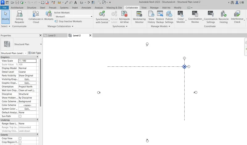
- First select the structural template, then the new project will be opened
- Next click on the collaborate tab, then the new tab will be visible
- Then click on the ok button.
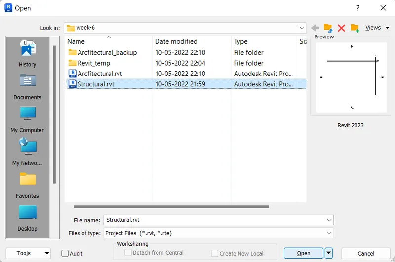
STEP-2
- Save the project as central model as shown below.
RESULT
saved the model as central file using collaborate tool in the structural model
7. AIM
To copy the grids from the architectural model to the structural model using Copy Monitor option
INTRODUCTION
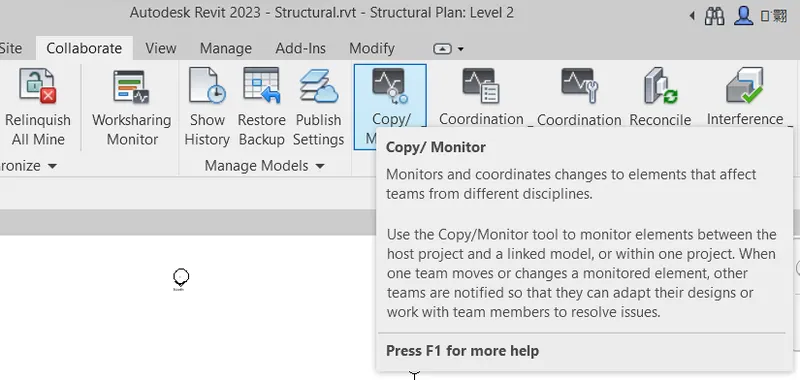
- When you start the Copy/Monitor tool, you can select Use Current Project or Select Link
- Then you can select Copy or Monitor: Copy: Creates a copy of a selected item and establishes a monitoring relationship between the copied element and the original element.
- If the original element changes, a warning alerts you when you open the project or reload the linked model. (This Copy tool is different than the other copy tools, which are used for copying and pasting)
- Monitor Establishes a monitoring relationship between 2 elements of the same type. If an element changes, a warning alerts you when you open the project or reload the linked model.
PROCECURE
STEP-1
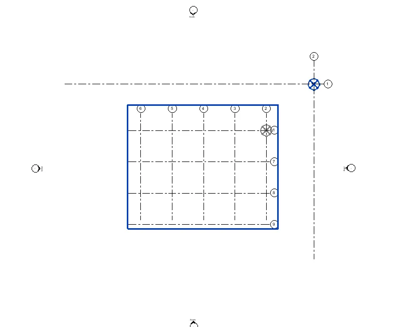
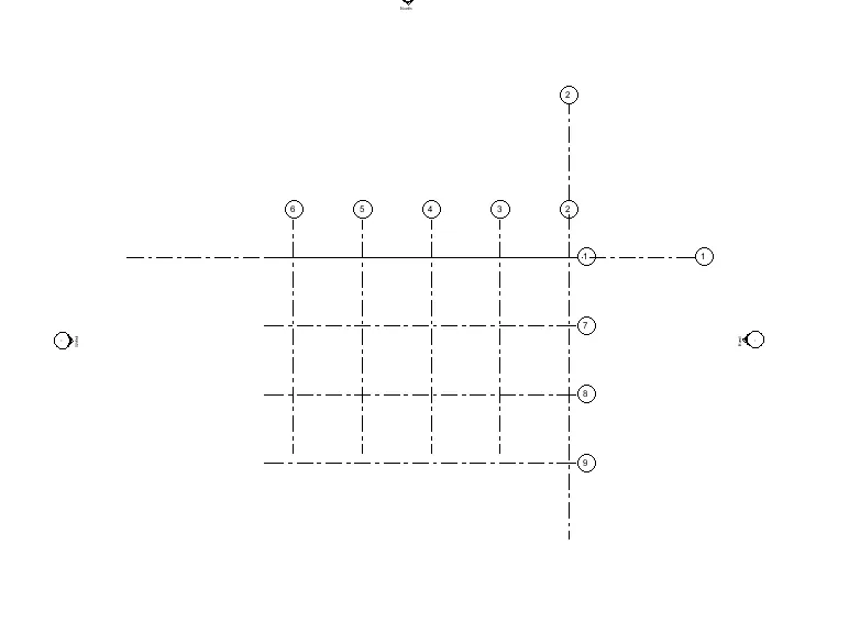
- First, we have to create the longitudinal grids and traverse grids, as shown below
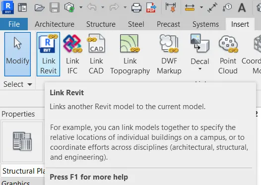
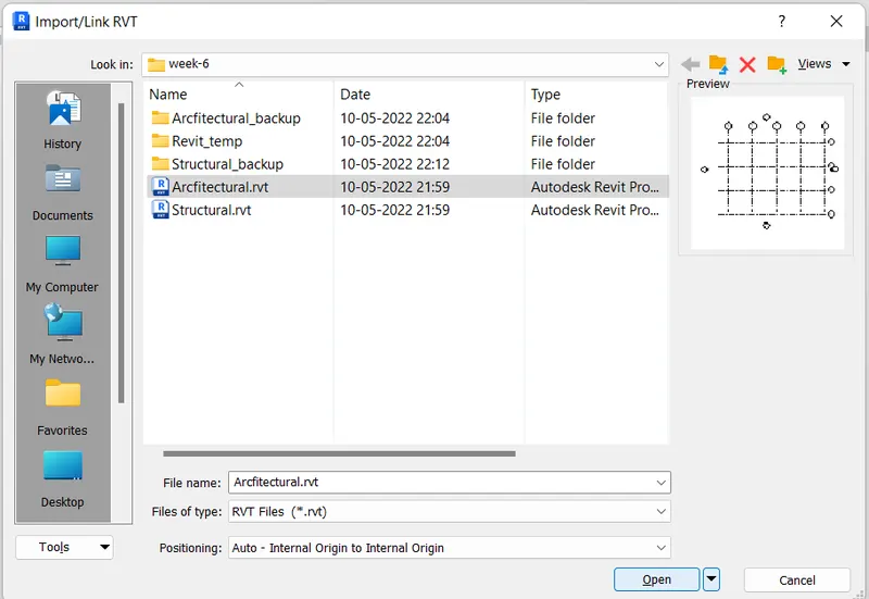
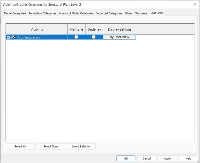
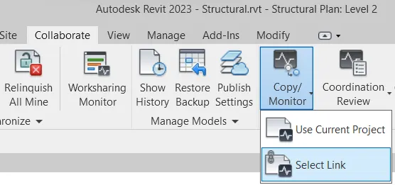
- Next, we select the copy/monitor tool, and click on the select link option, as shown below.
STEP-2
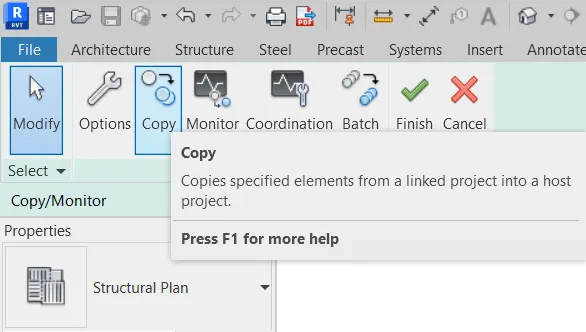
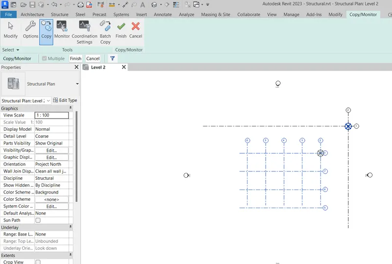
- After selecting copy/monitor, select the copy option and select the grids which you want to copy and press enter.
STEP-3
Copied the grids from architectural model to the structural model using the copy/monitor
RESULT
Successfully copy the grids from the architectural model to the structural model using Copy Monitor option
8.AIM
To create new file with a construction template and need to save the new file as central model. To link both architectural and structural files in a single project using the manage links tool
INTRODUCTION
- To manage a link in the model select it in the Manage Links dialog, and use an appropriate tool.
- You can select multiple links to modify by pressing Ctrl and clicking on the number of the link in the dialog
PROCEDURE
STEP-1
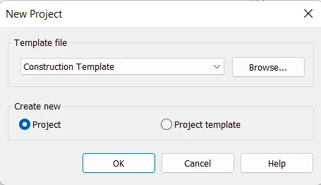
- First open a new project using the construction template, as shown below.
STEP-2
- Next the project tab will be opened.
STEP-3
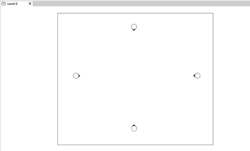
- Select the collaborate tool.
- click collaborate option
- click ok on the new tab visible.
STEP-4
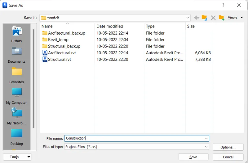
- Save the project as central model as shown below.
STEP-5
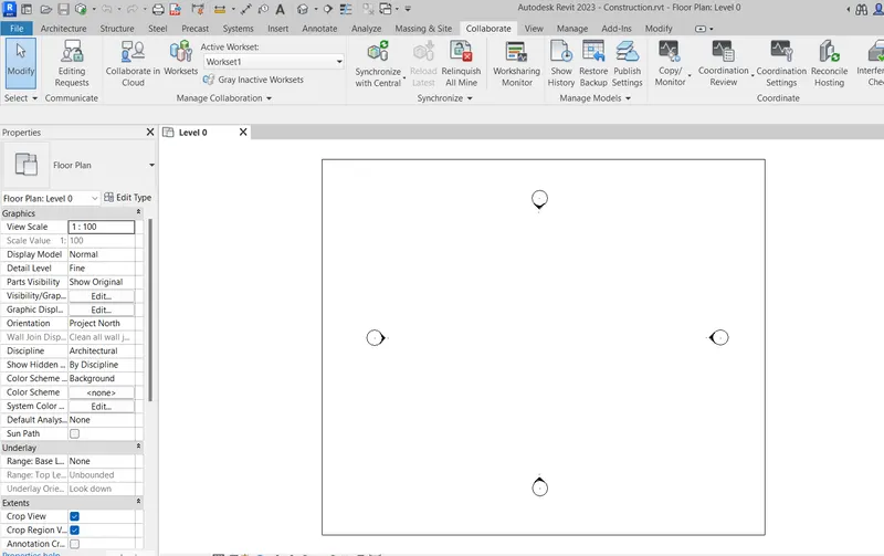
- synchronize option is visible
STEP-6
- new tab appears, click ok
STEP-7
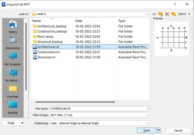
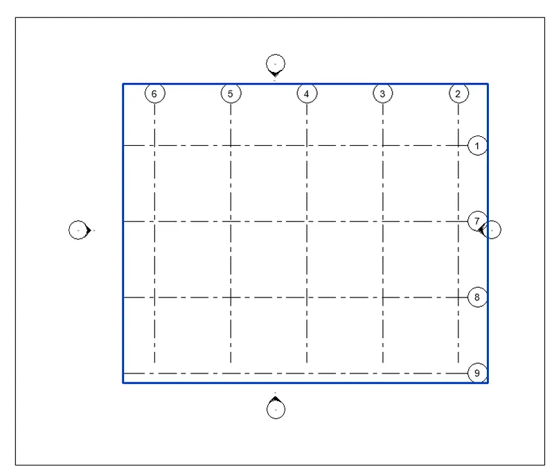
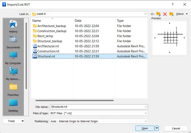
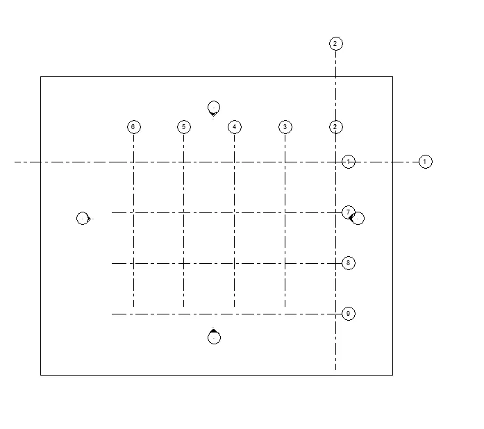
- click the manage links and link architectural and structural models.
- then click ok, the following grids will be displayed as result,
STEP-8
- next select the acquire coordinates and select the models and press enter.
STEP-9
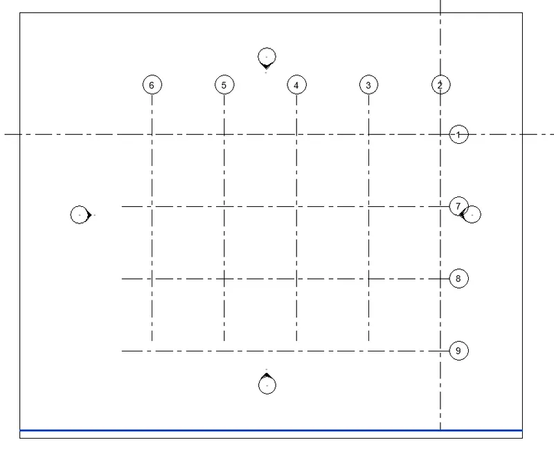
- Click the relocate option, select the points of both architectural and structural models visible on scree
STEP-10
- Both the structural and architectural model are linked
STEP-11
- save the file
RESULT
created new file with construction and saved as central model. Both the architectural and structural files are linked successfully in a single project.
9. Ans
YES, the grids from structural and architectural model matching in the construction template created. If yes, the model is set up for project 2.
10.
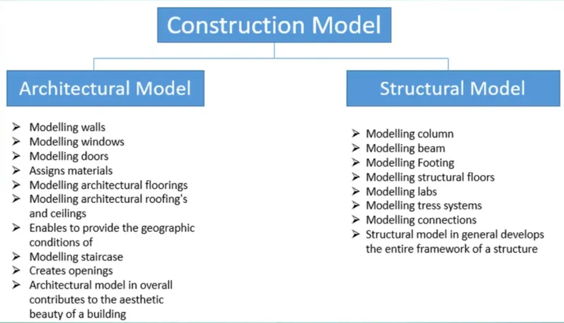
FOR CONSTRUCTION MODEL
- site access
- logistics and storage
- quality control
- outstanding contract details
- outstanding design-related challenges
- health and safety
FOR ACHITECTURAL MODEL
- Modelling walls
- Modelling windows
- Modelling doors
- Assigns materials
- Modelling architectural floorings
- Modelling architectural roofing's and ceilings
- Enables to provide the geographic conditions of
- Modelling staircase
- Creates openings
- Architectural model in overall contributes to the aesthetic beauty of a building
FOR STRUCTURAL MODEL
- Modelling column
- Modelling beam
- Modelling Footing
- Modelling structural floors
- Modelling labs
- Modelling tress systems
- Modelling connections
- Structural model in general develops the entire framework of a structure
The primary objective of structural analysis and design is to produce a structure capable of resisting all applied loads without failure during its intended life. If improperly designed, elements of a structure would fall causing serious consequences such as large expenses or ultimately losses in lives which cannot be compared with any cost.
Once the architectural engineer sets the function and layout of the structure, the role of the structural engineer begins which can be summarized in the following steps to develop a safe, functional and economic structures.
The number of people work in one projecct depends on the type of project such as it is in which group A or group B etc..