Creating a Floor plan, Footing detail and Isometric view using AutoCad
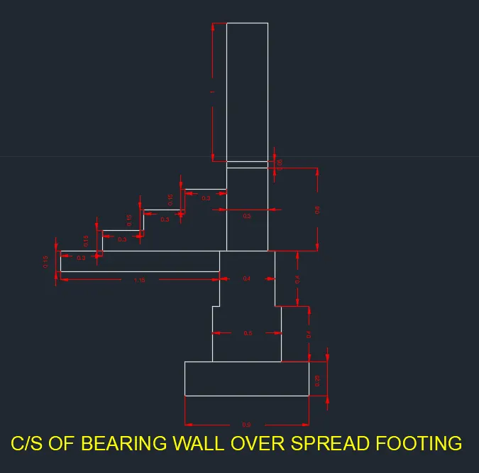
1. CROSS-SECTION OF LOAD BEARING WALL
AIM
To draw the cross-section of Load bearing wall over spread footing by using AutoCAD software
INTRODUCTION
This type of drawing can be drawn by using the line command or rectangle command with specifying the length and angle of the drawing
PROCEDURE
- Open AutoCAD software
- Choose the imperial template and start from scratch
- Set the units to decimal and select ok
- Ensure the dynamic input is off
- Choose line command by pressing 'L' enter and to give the dimensions to the command, the line was drawn.
- Indicate the direction of the line by line keeping ortho mode is ON
- Give the line measurement as per given in drawing as question
- After completion of drawing exit from line command and starting giving dimensions
- To give dimensions enter 'DIM'(Dimension) and select the line to locate the dimension in object
- To set the properties of dimension enter 'DIMS' (Dimension style) and specify the sizes as per requirements
- Now select the TEXT command and specify the name of the drawing in below
- To save the file, go to the AutoCAD application and choose the save as option
- Now select the snapping tool to take screenshot
RESULTS
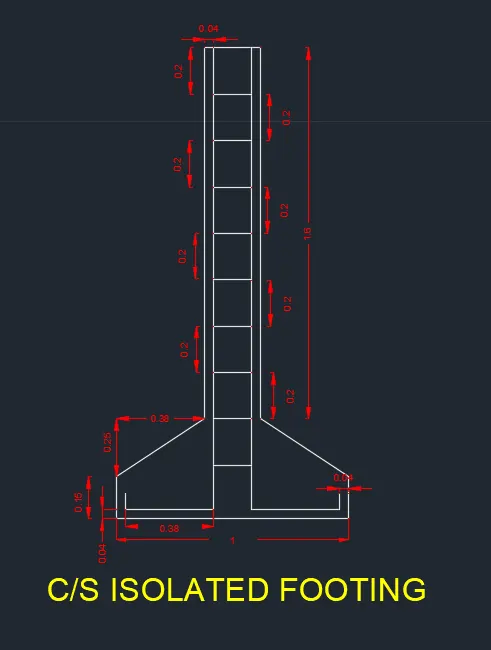
2.CROSS-SECTION ISOLATED FOOTING
AIM
To draw the cross-section of Isolated footing by using AutoCAD software
INTRODUCTION
This type of drawing can be drawn by using the line command, rectangle command, chamfer and path array command with specifying the length and angle of the drawing
PROCEDURE
- Open AutoCAD software
- Choose the imperial template and start from scratch
- Set the units to decimal and select ok
- Ensure the dynamic input is off
- Take rectangle command and specify the dimension, exit the rectangle command
- Now select the explode command to separate the rectangle command and select two line and choose chamfer to give the shape of isolated footing in the bottom by specifying the dimension
- Next select the offset command to give the offset according to given dimensions
- Next select the path array to give the centre-to-centre distance of bar
- After completion of drawing exit from command and starting giving dimensions
- To give dimensions enter 'DIM'(Dimension) and select the line to locate the dimension in object
- To set the properties of dimension enter 'DIMS' (Dimension style) and specify the sizes as per requirements
- Now select the TEXT command and specify the name of the drawing in below
- To save the file, go to the AutoCAD application and choose the save as option
- Now select the snapping tool to take screenshot
RESULTS
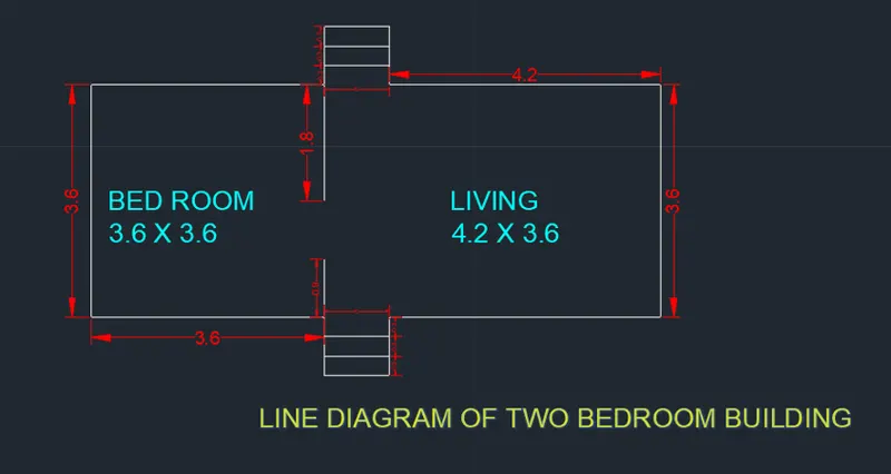
3. LINE DIAGRAM OF A TWO BEDROOM BUILDING
AIM
To draw the line diagram of a two-bedroom building by using AutoCAD software
INTRODUCTION
This type of drawing can be drawn by using the line command and rectangle command with specifying the length and angle of the drawing
PROCEDURE
- Open AutoCAD software
- Choose the imperial template and start from scratch
- Set the units to decimal and select ok
- Ensure the dynamic input is off
- Choose line command by pressing 'L' enter and to give the dimensions to the command, the line was drawn.
- Indicate the direction of the line by line keeping ortho mode is ON
- Give the line measurement as per given in drawing as question
- After completion of drawing exit from line command and starting giving dimensions
- To give dimensions enter 'DIM'(Dimension) and select the line to locate the dimension in object
- To set the properties of dimension enter 'DIMS' (Dimension style) and specify the sizes as per requirements
- Now select the TEXT command and specify the name of the drawing in below
- To save the file, go to the AutoCAD application and choose the save as option
- Now select the snapping tool to take screenshot
RESULTS
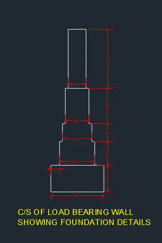
4. CROSS-SECTION OF LOAD BEARING WALL
AIM
To draw the cross-section of load bearing wall showing foundation details by using AutoCAD software
INTRODUCTION
This type of drawing can be drawn by using the line command and rectangle command with specifying the length and angle of the drawing
PROCEDURE
- Open AutoCAD software
- Choose the imperial template and start from scratch
- Set the units to decimal and select ok
- Ensure the dynamic input is off
- Choose line command by pressing 'L' enter and to give the dimensions to the command, the line was drawn.
- Indicate the direction of the line by line keeping ortho mode is ON
- Give the line measurement as per given in drawing as question
- After completion of drawing exit from line command and starting giving dimensions
- To give dimensions enter 'DIM'(Dimension) and select the line to locate the dimension in object
- To set the properties of dimension enter 'DIMS' (Dimension style) and specify the sizes as per requirements
- Now select the TEXT command and specify the name of the drawing in below
- To save the file, go to the AutoCAD application and choose the save as option
- Now select the snapping tool to take screenshot
RESULTS
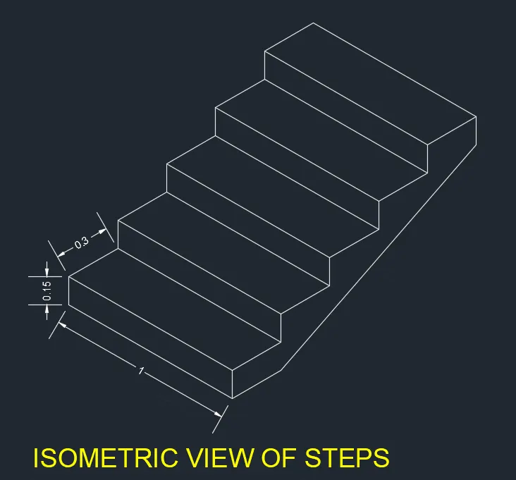
5. ISOMETRIC VIEW OF STEPS
AIM
To draw the isometric view of steps by using AutoCAD software
INTRODUCTION
This type of drawing can be drawn by using the line command in isometric drafting ON with specifying the length and changing the isometric view by F5
PROCEDURE
- Open AutoCAD software
- Choose the imperial template and start from scratch
- Set the units to decimal and select ok
- Ensure the dynamic input is off
- Choose the isometric drafting as ON and to give the dimensions to the command
- This isometric drafting is restricted to specific direction such as left, right and top to change this direction press F5
- After completion of drawing exit command and starting giving dimensions
- To give dimensions enter 'DIM'(Dimension) and select the line to locate the dimension in object
- To set the properties of dimension enter 'DIMS' (Dimension style) and specify the sizes as per requirements
- Now select the TEXT command and specify the name of the drawing in below
- To save the file, go to the AutoCAD application and choose the save as option
- Now select the snapping tool to take screenshot
RESULTS
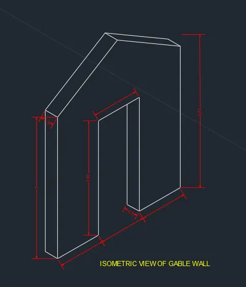
6. ISOMETRIC VIEW OF GABLE WALL
AIM
To draw the isometric view of gable wall by using AutoCAD software
INTRODUCTION
This type of drawing can be drawn by using the line command in isometric drafting ON with specifying the length and changing the isometric view by F5
PROCEDURE
- Open AutoCAD software
- Choose the imperial template and start from scratch
- Set the units to decimal and select ok
- Ensure the dynamic input is off
- Choose the isometric drafting as ON and to give the dimensions to the command
- This isometric drafting is restricted to specific direction such as left, right and top to change this direction press F5
- After completion of drawing exit command and starting giving dimensions
- To give dimensions enter 'DIM'(Dimension) and select the line to locate the dimension in object
- To set the properties of dimension enter 'DIMS' (Dimension style) and specify the sizes as per requirements
- Now select the TEXT command and specify the name of the drawing in below
- To save the file, go to the AutoCAD application and choose the save as option
- Now select the snapping tool to take screenshot
RESULTS