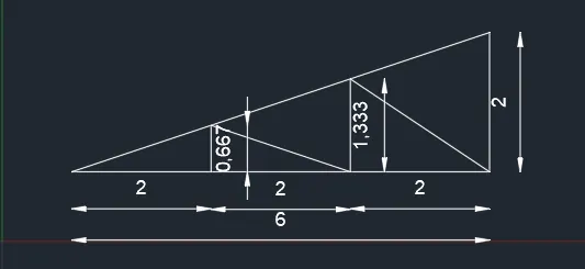
Creation of geometries by Coordinate system methods using AutoCad
P1 & P2
AIM
To draw the geometric object P1 & P2 using all the co-ordinate system methods, they are absolute co-ordinates, relative rectangular co-ordinates and relative polar co-ordinates.
INTRODUCTION
Absolute Co-ordinate system is a system in which drawing the object by 2 co-ordinates x-axis, y-axis. Relative co-ordinates are based on last point entered. Use relative coordinates when you know the location of a point in relation to the previous point.
PROCEDURE: (P1 Using absolute co-ordinate)
- Open AutoCAD software
- Choose the imperial template and start from scratch
- Set the units to decimal and select ok
- Ensure the dynamic input is off
- Choose line command by pressing 'L' enter
- Mark the 1st point as (2,1)
- Specify the 2nd point as (2,7))
- Specify the 3rd point as (8,7)
- Specify the 4th point as (8,6)
- Specify the 5th point as (3,6)
- Specify the 6th point as (3,2)
- Specify the 7th point as (8,2)
- Specify the 8th point as (8,1)
- And then 'C' enter for close the command to complete the drawing
- To give dimensions enter 'DIM'(Dimension) and select the line to locate the dimension in object
- To set the properties of dimension enter 'DIMS' (Dimension style) and specify the sizes as per requirements
RESULT:
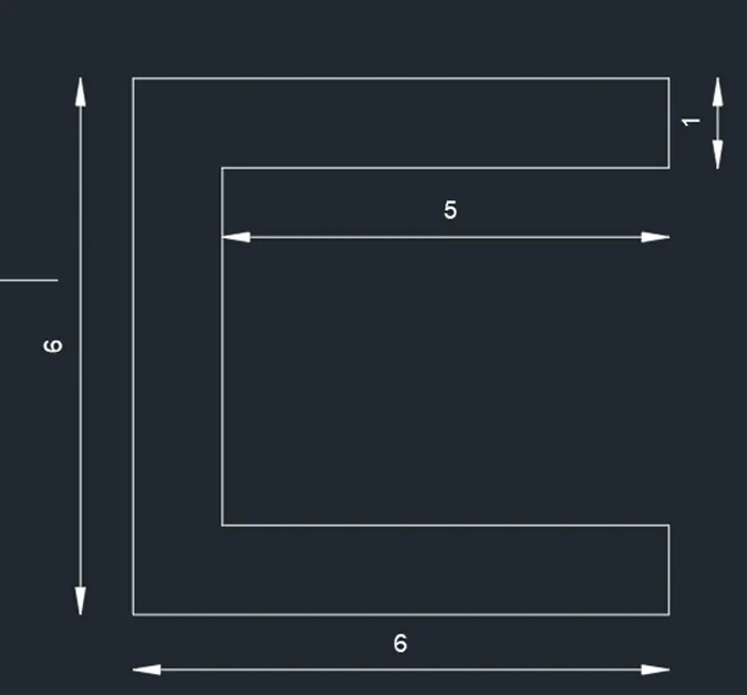
PROCEDURE: (P1 Using relative rectangular co-ordinates)
- Open AutoCAD software
- Choose the imperial template and start from scratch
- Set the units to decimal and select ok
- Ensure the dynamic input is off
- Choose line command by pressing 'L' enter
- Mark the 1st point as (2,1)
- Specify the 2nd point as (@ 6,0)
- Specify the 3rd point as (@ 0,1)
- Specify the 4th point as (@-5,0)
- Specify the 5th point as (@0,4)
- Specify the 6th point as (@5.0)
- Specify the 7th point as (@ 0,1)
- Specify the 8th point as (@-6,0)
- And then 'C' enter for close the command to complete the drawing
- To give dimensions enter 'DIM'(Dimension) and select the line to locate the dimension in object
- To set the properties of dimension enter 'DIMS' (Dimension style) and specify the sizes as per requirements
RESULT:
PROCEDURE: (P1 Using Relative Polar co-ordinates)
- Open AutoCAD software
- Choose the imperial template and start from scratch
- Set the units to decimal and select ok
- Ensure the dynamic input is off.
- Choose line command by pressing 'L' enter
- Mark the 1st point as (2,1)
- Specify the 2nd point as (@6<0)
- Specify the 3rd point as (@ 1<90)
- Specify the 4th point as (@5<180)
- Specify the 5th point as (@ 4<90)
- Specify the 6th point as (@ 5<0)
- Specify the 7th point as (@ 1<90)
- Specify the 8th point as (@6<180)
- And then 'C' enter for close the command to complete the drawing
- To give dimensions enter 'DIM'(Dimension) and select the line to locate the dimension in object
- To set the properties of dimension enter 'DIMS' (Dimension style) and specify the sizes as per requirements
RESULT:
PROCEDURE: For P2 Using absolute co-ordinate
- Open AutoCAD software
- Choose the imperial template and start from scratch
- Set the units to decimal and select ok
- Ensure the dynamic input is off
- Choose line command by pressing 'L' enter
- Mark the 1st point as (2.1)
- Specify the 2nd point as (5,1)
- Specify the 3rd point as (5,5)
- Specify the 4th point as (6,5)
- Specify the 5th point as (6,1)
- Specify the 6th point as (9,1)
- Specify the 7th point as (7,8)
- Specify the 8th point as (4,8)
- And then 'C' enter for close the command to complete the drawing
- To give dimensions enter 'DIM'(Dimension) and select the line to locate the dimension in object
- To set the properties of dimension enter 'DIMS' (Dimension style) and specify the sizes as per requirements
RESULT:
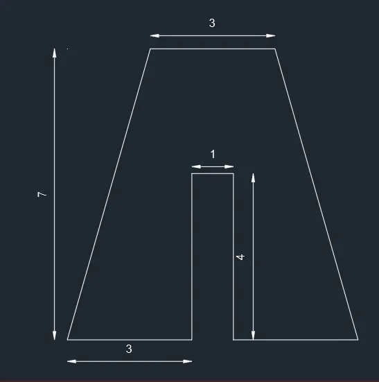
PROCEDURE: For P2 Using relative rectangular co-ordinates
- Open AutoCAD software
- Choose the imperial template and start from scratch
- Set the units to decimal and select ok
- Ensure the dynamic input is off
- Choose line command by pressing 'L' enter
- Mark the 1st point as (2,1)
- Specify the 2nd point as (@ 3,0)
- Specify the 3rd point as (@ 0,4)
- Specify the 4th point as (@ 1,0)
- Specify the 5th point as (@0,-4)
- Specify the 6th point as (@ 3,0)
- Specify the 7th point as (@-2,7)
- Specify the 8th point as (-3,0)
- And then 'C' enter for close the command to complete the drawing
- To give dimensions enter 'DIM'(Dimension) and select the line to locate the dimension in object
- To set the properties of dimension enter 'DIMS' (Dimension style) and specify the sizes as per requirements
RESULT:
PROCEDURE: For P2 Using Relative Polar co-ordinates
- Open AutoCAD software
- Choose the imperial template and start from scratch ok
- Set the units to decimal and select
- Ensure the dynamic input is off
- Choose line command by pressing 'L' enter
- Mark the 1st point as (2,1)
- Specify the 2nd point as (@ 3<0)
- Specify the 3rd point as (@ 4<90)
- Specify the 4th point as (@ 1<0)
- Specify the 5th point as (@4<270)
- Specify the 6th point as (@ 3<0)
- Specify the 7th point as (@7.28<106)
- Specify the 8th point as (@3<180)
- And then 'C' enter for close the command to complete the drawing
- To give dimensions enter 'DIM'(Dimension) and select the line to locate the dimension in object
- To set the properties of dimension enter 'DIMS' (Dimension style) and specify the sizes as per requirements
RESULT:
P4
AIM:
To draw the Geometrical object P4 using any co-ordinate system methods
INTRODUCTION:
Absolute Co-ordinate system is a system in which drawing the object by 2 co-ordinates x-axis, y-axis. Relative co-ordinates are based on last point entered. Use relative coordinates when you know the location of a point in relation to the previous point.
PROCEDURE: For P4 Using absolute co-ordinate
- Open AutoCAD software
- Choose the imperial template and start from scratch
- Set the units to decimal and select ok
- Ensure the dynamic input is off
- Choose line command by pressing 'L' enter
- Mark the 1st point as (2,1)
- Specify the 2nd point as (3,1)
- Specify the 3rd point as (3,5)
- Specify the 4th point as (5,3)
- Specify the 5th point.as (7,5)
- Specify the 6th point as (7,1)
- Specify the 7th point as (8,1)
- Specify the 8th point as (8,8)
- Specity the 9th point as (7.8)
- Specify the 10th point as (5.5)
- Specify the 11th point as (3,8)
- Specify the 12th point as (2,8)
- And then 'C' enter for close the command to complete the drawing
- To give dimensions enter 'DIM'(Dimension) and select the line to locate the dimension in object
- To set the properties of dimension enter 'DIMS' (Dimension style) and specify the sizes as per requirements
RESULT:
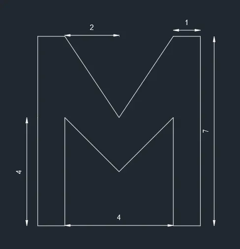
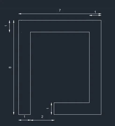
P5
AIM:
To draw the geometric object P5 using any co-ordinate system methods
INTRODUCTION:
Absolute Co-ordinate system is a system in which drawing the object by 2 co-ordinates x-axis, y-axis. Relative co-ordinates are based on last point entered. Use relative coordinates when you know the location of a point in relation to the previous point
PROCEDURE For P5 Using absolute co-ordinate
- Open AutoCAD software
- Choose the imperial template and start from scratch
- Set the units to decimal and select ok
- Ensure the dynamic input is off
- Choose line command by pressing 'L' enter
- Mark the 1st point as (2,1)
- Specify the 2nd point as (3,1)
- Specify the 3rd point as (3,8)
- Specify the 4th point as (8,8)
- Specify the 5th point as (8,2)
- Specify the 6th point as (5,2)
- Specify the 7th point as (5,1)
- Specify the 8th point as (9,1)
- Specify the 9th point as (9,9)
- Specify the 10th point as (2,9)
- And then 'C' enter for close the command to complete the drawing
- To give dimensions enter 'DIM'(Dimension) and select the line to locate the dimension in object
- To set the properties of dimension enter 'DIMS' (Dimension style) and specify the sizes as per requirements
RESULT:
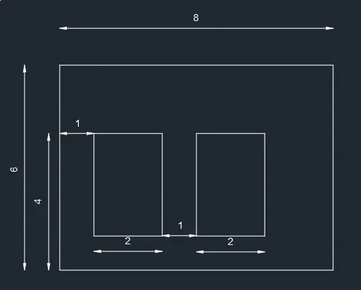
P7
AIM:
To draw the geometric object P7 using any co-ordinate system methods.
INTRODUCTION:
Absolute Co-ordinate system is a system in which drawing the object by 2 co-ordinates x-axis, y-axis. Relative co-ordinates are based on last point entered. Use relative coordinates when you know the location of a point in relation to the previous point
PROCEDURE For P7 Using absolute co-ordinate
- Open AutoCAD software
- Choose the imperial template and start from scratch
- Set the units to decimal and select ok
- Ensure the dynamic input is off
- Choose line command by pressing 'L' ente
- Mark the 1st point as (2,1)
- Specify the 2nd point as (10,1)
- Specify the 3rd point as (10,7)
- Specify the 4th point as (2,7)
- Close the line command and Start from (3,2)
- Specify the next point as (5,2)
- Specify the next point as (5,5)
- Specify the next point as (3,5)
- Close the line command and Start from (6,2)
- Specify the next point as (8,2)
- Specify the next point as (8,5)
- Specify the next point as (6,5)
- And then 'C' enter for close the command to complete the drawing
- To give dimensions enter 'DIM'(Dimension) and select the line to locate the dimension in object
- To set the properties of dimension enter 'DIMS' (Dimension style) and specify the sizes as per requirements
RESULT:
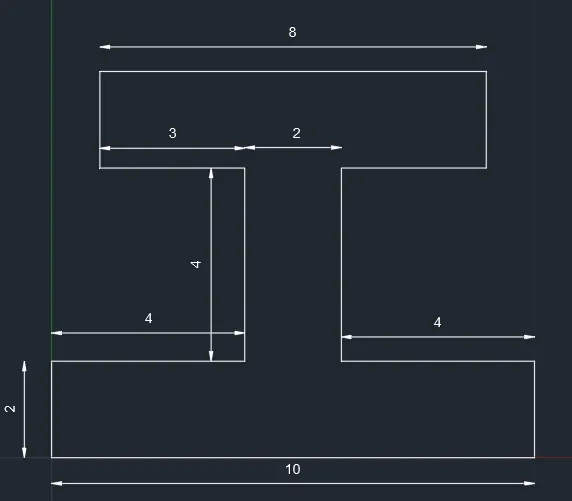
P8
AIM:
To draw the geometric object P8 using any co-ordinate system methods
INTRODUCTION:
Absolute Co-ordinate system is a system in which drawing the object by 2 co-ordinates x-axis, y-axis. Relative co-ordinates are based on last point entered. Use relative coordinates when you know the location of a point in relation to the previous point
PROCEDURE: For P8 Using Relative Polar co-ordinates
- Open AutoCAD software
- Choose the imperial template and start from scratch
- Set the units to decimal and select ok
- Ensure the dynamic input is off
- Choose line command by pressing 'L' enter
- Mark the 1st point as (0,0)
- Specify the 2nd point as (@10<0)
- Specify the 3rd point as (@ 2<90)
- Specify the 4th point as (@4<180)
- Specify the 5th point as (@4<90)
- Specify the 6th point as (@3<0)
- Specify the 7th point as (@2<90)
- Specify the 8th point as (@8<180)
- Specify the 9th point as (@2<270)
- Specify the 10th point as (@3<0)
- Specify the 11th point as (@4<270)
- Specify the 12th point as (@4<180)
- And then 'C' enter for close the command to complete the drawing
- To give dimensions enter 'DIM'(Dimension) and select the line to locate the dimension in object
- To set the properties of dimension enter 'DIMS' (Dimension style) and specify the sizes as per requirements
RESULT:
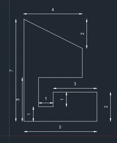
P9
AIM:
To draw the geometric object P9 using any co-ordinate system methods.
INTRODUCTION
Absolute Co-ordinate system is a system in which drawing the object by 2 co-ordinates x-axis, y-axis. Relative co-ordinates are based on last point entered. Use relative coordinates when you know the location of a point in relation to the previous point
PROCEDURE For P9 Using Relative Polar co-ordinates and Absolute Co-ordinates system
- Open AutoCAD software
- Choose the imperial template and start from scratch
- Set the units to decimal and select ok
- Ensure the dynamic input is off
- Choose line command by pressing 'L' enter
- Mark the 1st point as (1,1)
- Specify the 2nd point as (@5<0)
- Specify the 3rd point as (@ 2<90)
- Specify the 4th point as (@3<180)
- Specify the 5th point as (@1<270)
- Specify the 6th point as (@1<180)
- Specify the 7th point as (@2<90)
- Specify the 8th point as (@3<0)
- Specify the 9th point as (@2<90)
- Specify the 10th point as (1,8)
- And then 'C' enter for close the command to complete the drawing
- To give dimensions enter 'DIM'(Dimension) and select the line to locate the dimension in object
- To set the properties of dimension enter 'DIMS' (Dimension style) and specify the sizes as per requirements
RESULT:
P10
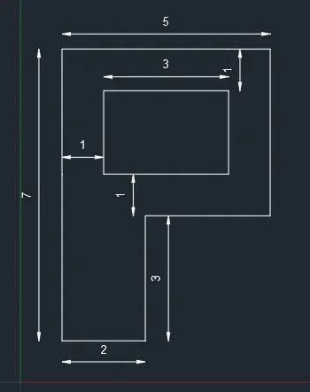
AIM:
To draw the geometric object P10 using any co-ordinate system methods.
INTRODUCTION:
Absolute Co-ordinate system is a system in which drawing the object by 2 co-ordinates x-axis, y-axis. Relative co-ordinates are based on last point entered. Use relative coordinates when you know the location of a point in relation to the previous point
PROCEDURE: P10 Using Relative Polar co-ordinates and Absolute Co-ordinates system
- Open AutoCAD software
- Choose the imperial template and start from scratch
- Set the units to decimal and select ok
- Ensure the dynamic input is off
- Choose line command by pressing 'L' enter
- Mark the 1st point as (1,1)
- Specify the 2nd point as (@2<0)
- Specify the 3rd point as (@3<90)
- Specify the 4th point as (@3<0)
- Specify the 5th point as (@4<90)
- Specify the 6th point as (@5<180)
- Close the line command and Start from (2,5)
- Specify the next point as (@3<0)
- Specify the next point as (@2<90)
- Specify the next point as (@3<180)
- And then 'C' enter for close the command to complete the drawing
- To give dimensions enter 'DIM'(Dimension) and select the line to locate the dimension in object
- To set the properties of dimension enter 'DIMS' (Dimension style) and specify the sizes as per requirements
RESULT
PROFILE WOOD
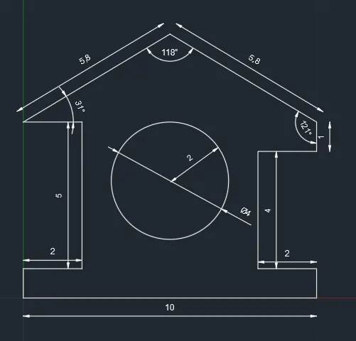
AIM:
To draw the PROFILE WOOD diagram using any co-ordinate system methods
INTRODUCTION
Absolute Co-ordinate system is a system in which drawing the object by 2 co-ordinates x-axis, y-axis. Relative co-ordinates are based on last point entered. Use relative coordinates when you know the location of a point in relation to the previous point
PROCEDURE For Profile wood Using Relative Polar co-ordinates and Absolute Co-ordinates system
- Open AutoCAD software
- Choose the imperial template and start from scratch
- Set the units to decimal and select ok
- Ensure the dynamic input is off
- Choose line command by pressing 'L' enter
- Mark the 1st point as (0,0)
- Specify the 2nd point as (@10<0)
- Specify the 3rd point as (@1<90)
- Specify the 4th point as (@2<180)
- Specify the 5th point as (@4<90)
- Specify the 6th point as (@2<0)
- Specify the 7th point as (@1<90)
- Specify the 8th point as (5,9)
- Specify the 9th point as (0,6)
- Specify the 10th point as (@2<0)
- Specify the 11th point as (@5<270)
- Specify the 12th point as (@2<180)
- Close the line command and Draw a circle of radius 2 with center point as (5.4)
- To give dimensions enter 'DIM'(Dimension) and select the line to locate the dimension in object
- To set the properties of dimension enter 'DIMS' (Dimension style) and specify the sizes as per requirements
RESULT
QUEEN POST TRUSS
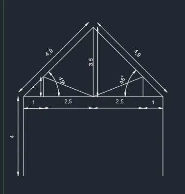
AIM:
To draw the QUEEN POST TRUSS diagram using any co-ordinate system methods
INTRODUCTION:
Absolute Co-ordinate system is a system in which drawing the object by 2 co-ordinates x-axis, y-axis. Relative co-ordinates are based on last point entered. Use relative coordinates when you know the location of a point in relation to the previous point
PROCEDURE: For Queen post truss Using Relative Polar co-ordinates and Absolute Co-ordinates system
- Open AutoCAD software
- Choose the imperial template and start from scratch
- Set the units to decimal and select ok
- Ensure the dynamic input is off
- Choose line command by pressing 'L' enter
- Mark the 1st point as (1,1)
- Specify the 2nd point as (@4<90)
- Specify the 3rd point as (4.5,8.5)
- Specify the 4th point as (8,5)
- Specify the 5th point as (@4<270)
- Close the line and start the line command and specify the point as (1,5)
- Specify the next point as (8,5)
- Close the line commnad and press space button for repeat the line command and specify the point as (4.5,8.5)
- Specify the point as (@3.5<270)
- Specify the next point as (2,6)
- Specify the next point as (@1<270)
- Close the line commnad and press space button for repeat the line command and specify the point as (7,5)
- Specify the next point as (@1<90)
- Specify the next point as (4.5,5) and close the line command by pressing esc buttom
- To give dimensions enter 'DIM'(Dimension) and select the line to locate the dimension in object
- To set the properties of dimension enter 'DIMS' (Dimension style) and specify the sizes as per requirements
RESULT:
MONO PITCH
AIM:
To draw the MONOPITCH diagram using any co-ordinate system methods
INTRODUCTION:
Absolute Co-ordinate system is a system in which drawing the object by 2 co-ordinates x-axis, y-axis. Relative co-ordinates are based on last point entered. Use relative coordinates when you know the location of a point in relation to the previous point
PROCEDURE: For mono pitch Using Relative Polar co-ordinates and Absolute Co-ordinates system
- Open AutoCAD software
- Choose the imperial template and start from scratch
- Set the units to decimal and select ok
- Ensure the dynamic input is off
- Choose line command by pressing 'L' enter
- Mark the 1st point as (1,1)
- Specify the 2nd point as (@6<0)
- Specify the 3rd point as (@2<90)
- Close the line command and Start from (3,1)
- Specify the next point (@0.667<90)
- Specify the next point as (5,1)
- Then specify next point as (@1.333<90)
- Specify the next point as (7,1)
- To give dimensions enter 'DIM'(Dimension) and select the line to locate the dimension in object
- To set the properties of dimension enter 'DIMS' (Dimension style) and specify the sizes as per requirements
RESULT