Usage of Collaborate tool in REVIT
1)
AIM:
To open an architectural template and then to use the manage tab to set project base point and project shared coordinates.
PROCEDURE:
- Open Revit
- Open a new architectural template in Revit
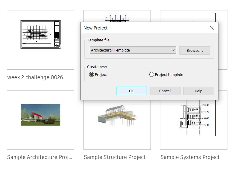
- Save the file to a destined location
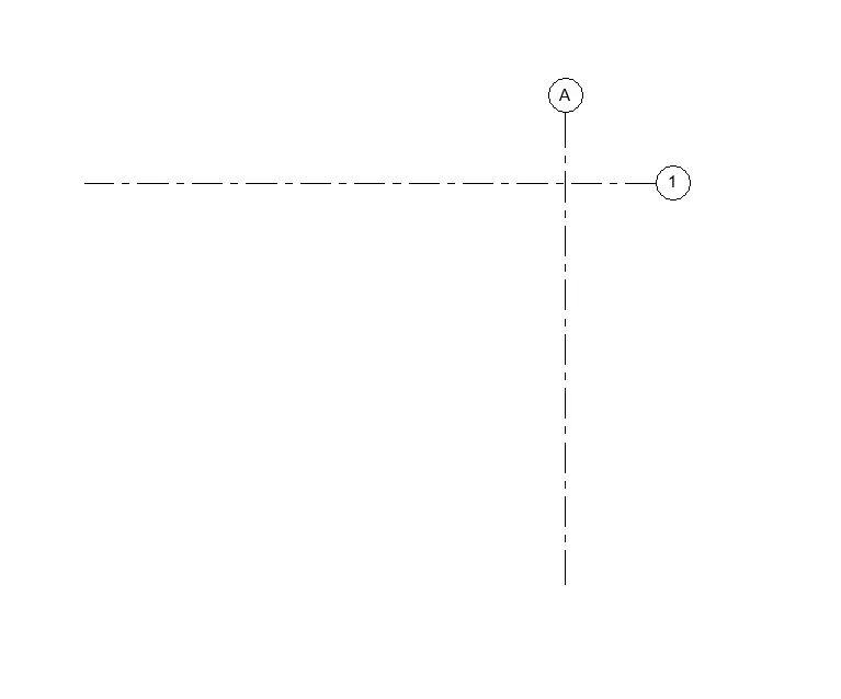
- Go to architectural tab then select the grid option and draw a vertical and horizontal grid. Name the vetical grid alphabetically and the horizontal one numerically

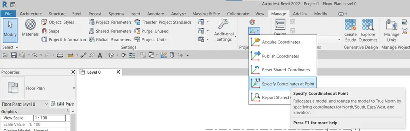
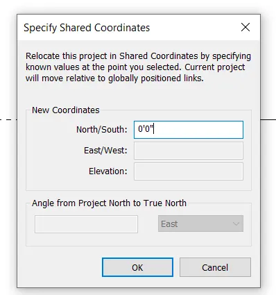
- Go to manage tab, select the "Specify Coordinates at point" option as shown in the figure.
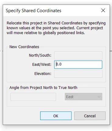
- Specify the vertical and horizontal grid coordinates as 0'0" in the pop up
RESULT:
Project base point and the shared point coordinate has been set for the architectural template file.
2)
AIM:
To open another new file but with a structural template and using the manage tab set project parameters the same as the architectural model (Copy the parameters from the architectural model to the structural template or enter the parameters manually into the structural model)
PROCEDURE:
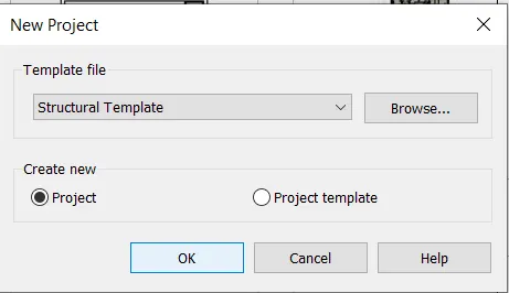
- Open a new file in revit
- Now select structural template
- Save the file to a destined location
- Go to structural tab, select grid option to draw horizotal and vertical grids and name vertical grids alphabetically and the horizontal grids numerically
- Go to manage tab, select the "Specify Coordinates at point" option as shown in the figure.
- Specify the vertical and horizontal grid coordinates as 0'0" in the pop up
RESULT:
Project base point and the shared point coordinate has been set for the structural template file.
3)
AIM:
To re-open the architectural model and to use the tools under the Collaborate tab to make the architectural model a central model
PROCEDURE:
- Open the architectural template file created in the revit
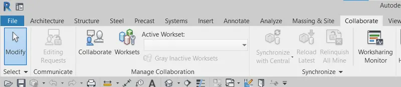
- Go to collaborate tab and click on collaborate option
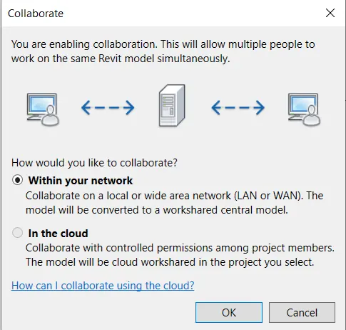
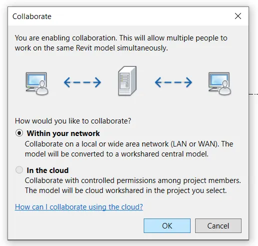
- Then a dialogue box pops up asking if you need the local LAN network to use or cloud collaborating, if work is done within an organization then it is suggestible to use local LAN network for collaborating and then click OK
- Now save the project
- It pops up saying its the first time you are sharing your work after making it as shareable, then click yes
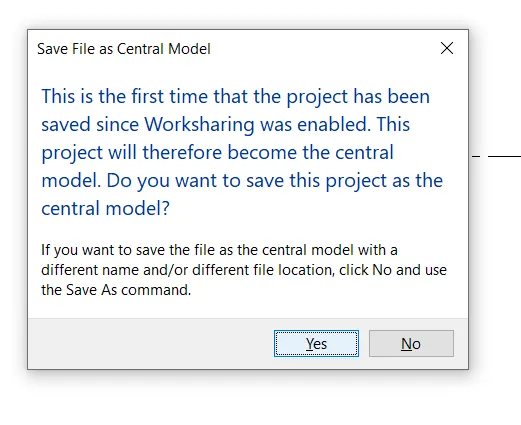
RESULT:
Now our architectural model is made a central model
4)
AIM:
To create a grid system longitudinally and transversely at a distance of 30 ft
PROCEDURE:
- Open the architectural template file that we have saved earlier
- Go to the architectural tab and select the grid option
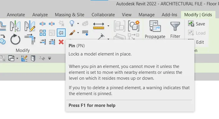
- Select the previously drawn horizontal and vertical system and selct the pin option from modify tab so that their coordinates remain fixed
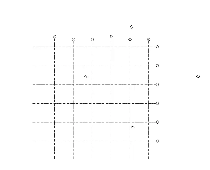
- Continue drawing all the grid lines both horizontal and vertical at 30 ft distance
RESULT:
A grid system of longitudinal and transverse grid lines is formed at a distance of 30 ft
5)
AIM:
To synchronize the changes from the local copy to the central file of the architectural model.
PROCEDURE:
- Go to collaborate tab to synchronise the changes made in architectural template
- Select the synchronise and modify the settings option
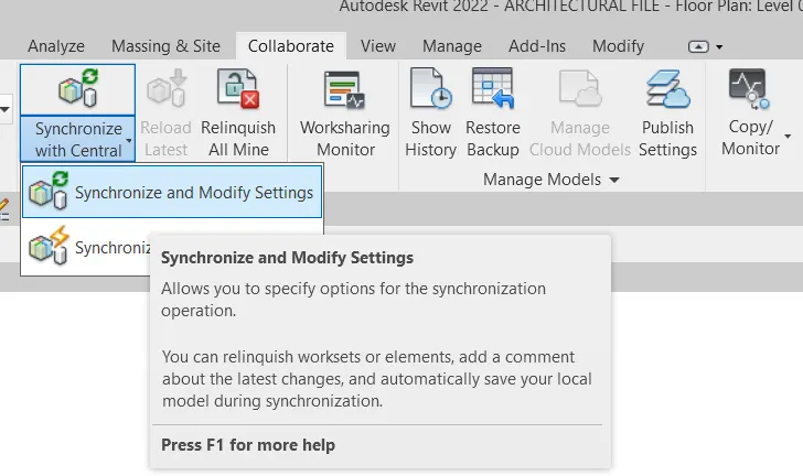
- Now click ok in the dialogue box that appears
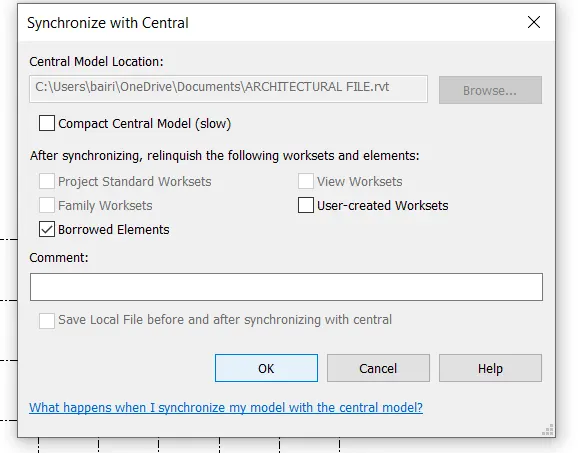
RESULT:
The architectural template of our project has been successfully synchronised.
6)
AIM:
To open the structural model and use the collaborate tools to save the model as a central file.
PROCEDURE:
- Open the previously saved structural template file.
- Go to collaborate tab and click on the collaborate option
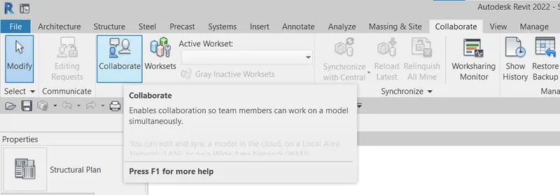
- Then a dialogue box pops up asking if you need the local LAN network to use or cloud collaborating, if work is done within an organization then it is suggestible to use local LAN network for collaborating and then click OK
- Now save the project
- It pops up saying its the first time you are sharing your work after making it as shareable, then click yes
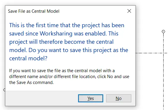
RESULT:
The structural file has been saved as a central file.
7)
AIM:
To select the grids and levels from the architectural model, and using Copy Monitor try to copy the grids to the structural model
PROCEDURE:
- Open the structural file created in the revit
- Go to manage option and click on manage link option
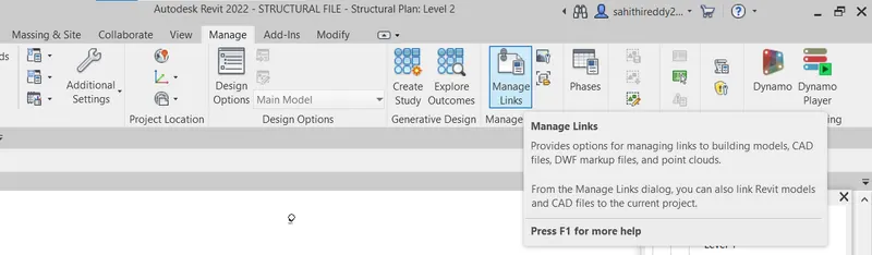
- In the dialogue box that follows click on add option and then locate the file to select it
- Click on ok
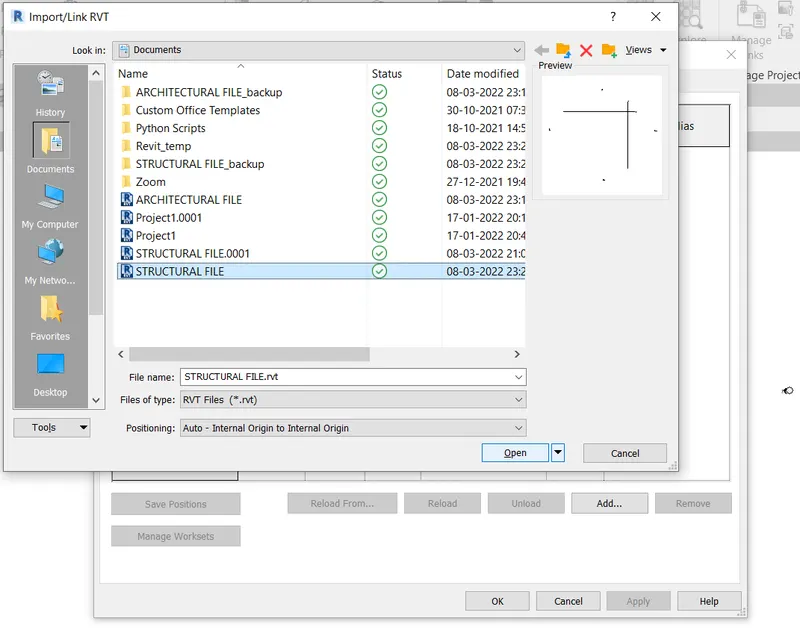
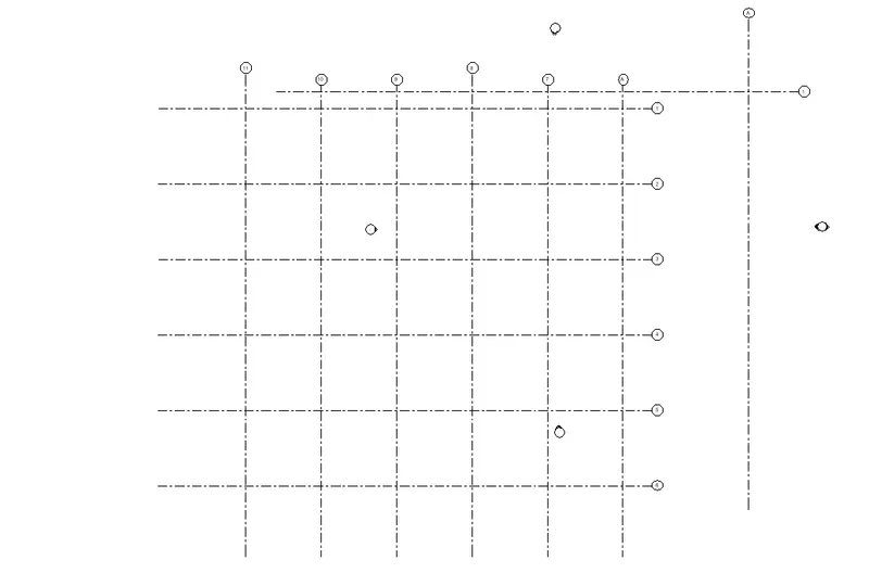
- Now we will see the grid system gets added to the structural model from the architectural model but despite the coordinates being 0'0" they are not overlapped
- Now go to the collaborate tab and select the copy/ monitor option and then select the "select link" option
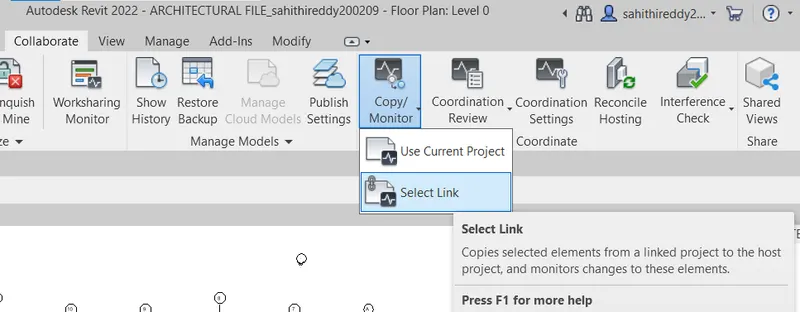
- Now select the grid system that has been linked to the structural file, click on copy option and then select all the grid lines that we want to copy and click finish
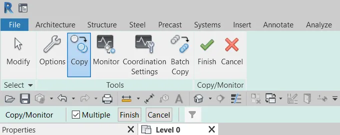
- You will now see that the both grids has been overlapped
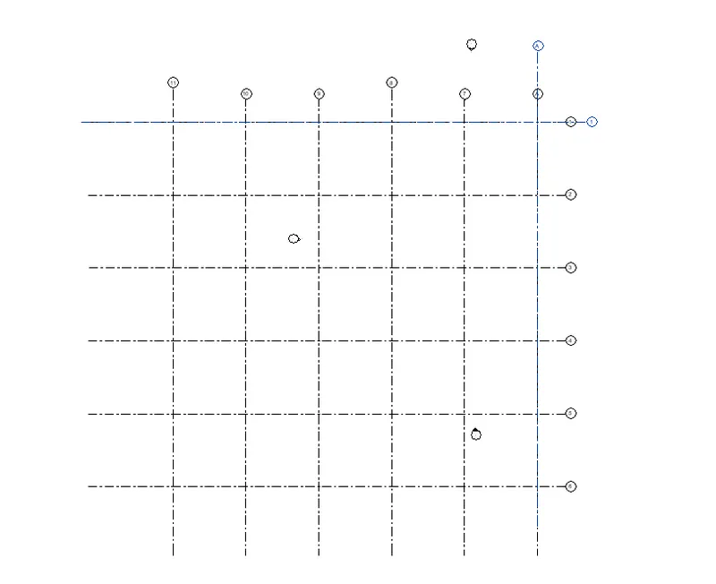
- Click on green tick, finish option
RESULT:
The grid system drawn in the architectural file has been successfully linked and monitored to the structural file.
8)
AIM:
To create another new file with a construction template. Save the new file as a central model. This file will include both architectural and structural model. Under the manage tab, Click manage links to link both architectural and structural files. Save the file and close all the files.
PROCEDURE:
- Open a new file in revit chosing construction template
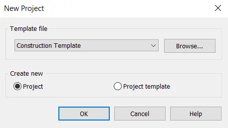
- Save the file to a destined location
- Go to colaborate tab and click on collaborate option and choose to collaborate within your network option
- Save the project
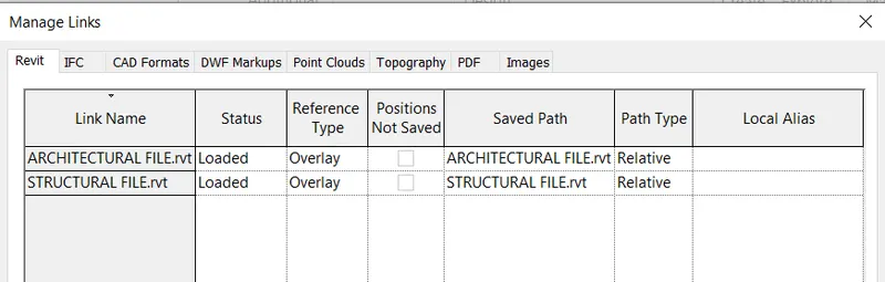
- Now go to manage tab and click on manage link option
- A dialogue box pops up and now select previously created architectural and structural files
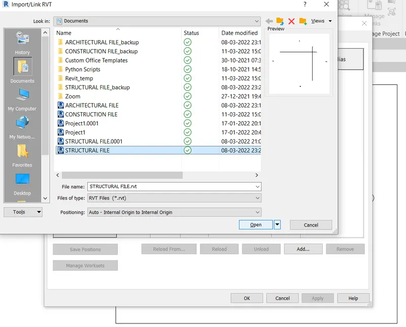
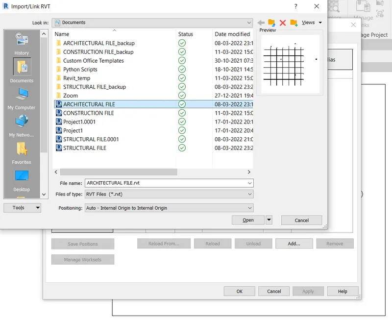
- Click OK
RESULT:
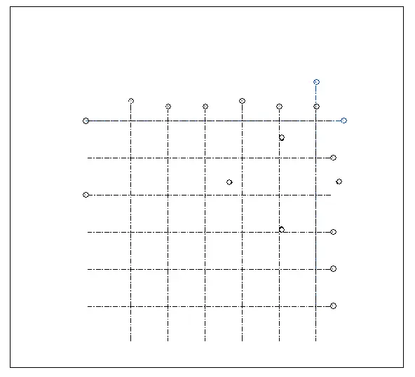
Both architectural and structural files have been linked to a new construction template file and the new file has been set as a central file
9)
AIM:
To link the model based on shared coordinates since the grids are not matching in the construction template
PROCEDURE:
- Open revit
- Open the construction template file
- Click on either of architectural or structural files created. Go to modify tab and select the move option
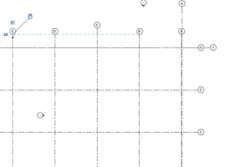
- Click on standard grids and move them in such a way that it matches the other template grids
- Now go to manage tab, select the specify coordinates option to specify the coordinates of standard vertical and horizontal grids to 0'0"
- Save the project to a destined location
RESULT:
We have linked the grid system perfectly
10)
AIM:
To make the flow chart of a project tree set up in terms of Construction model, Architecture & Structure model.
PROCEDURE:
- From the project that has been set up, people from different domains can work simultaneously on the revit.
- Flow chart of terms of both architectural and structural models is displayed below
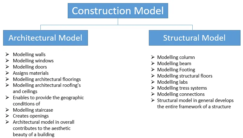
RESULT:
Flowchart describing the work that can be done simultaneously in revit using both architectural and structural models is shown above.