Turbo Charger Simulation Project
TURBO CHARGER SIMULATION
AIM:
To run the simulation process for turbo charger with three different pressure ratios.
- Pressure ratio- 2
- Pressure ratio- 2.5
- Pressure ratio- 3
OBJECTIVE:
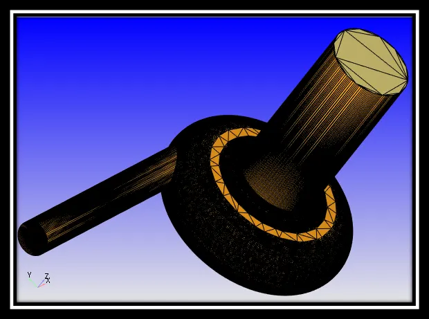
A turbocharger is a device that is used to increase the power of engine or one can say efficiency of engine by increasing the amount of air entering into the combustion chamber. More air into the combustion chamber means more amount of fuel will be admitted into the cylinder and as a result one will get more power from the same engine if the turbocharger are installed it.
TURBOCHARGER AND ITS WORKING:
Many people confuses between the turbocharger and supercharger. The function of the supercharger is same as that of turbocharger but the supercharger is driven mechanically by the engine, often with the help of belt connected to the crankshaft, whereas turbocharger is powered by a turbine driven by the engine’s exhaust gases. Turbocharger is considered more efficient than the superchargers as they are using the wasted energy of exhaust gases for its power source.
OPERATING PRINCIPLE OF TURBOCHARGER:
The amount of engine that actually goes into the engine’s cylinder, compared with the theoretical amount if the engine could maintain the atmospheric pressure is called volumetric efficiency and the aim of turbocharger is to improve an engine’s volumetric efficiency by increasing density of the intake gas.
The turbocharger draws the air from atmosphere and compresses it with the help of centrifugal compressor before it enters into the intake manifold at increased pressure. This results in more amount of air entering into the cylinder on each intake stroke. The centrifugal compressor gets power from the kinetic energy of engine’s exhaust gases.
The turbocharger has three main components:
- The turbine, which is almost a radial inflow turbine.
- The compressor which is almost a centrifugal compressor.
- The centre hub rotating assembly.
WORKING OF THE TURBOCHARGER:
A turbocharger mainly consists of two main sections: the turbine and the compressor. The turbine consists of turbine wheel and the turbine housing where purpose is to guide to exhaust gases into the turbine wheel. The kinetic energy of the exhaust gases gets converted into the mechanical after striking it on turbine blades. The exhaust outlet helps the exhaust gases to get exit from the turbine. The compressor wheel in turbocharger is attached to a turbine with the help of steel shaft and as the turbine turns the compressor wheel, it draws the high velocity, low pressure air stream and convert it into high pressure, low velocity air stream. This compressed air is pushed into the engine with the more quantity of fuel and hence produces more power.
CASE SETUP:
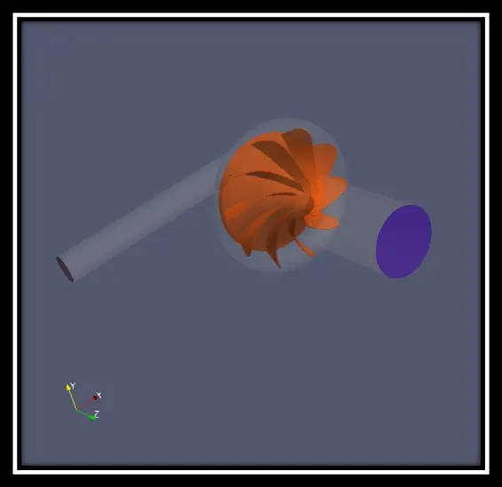
For the simulation process, air is selected for the flow. In run parameters, transient mode is selected for solver the simulation mode is full hydrodynamic and the gas flow solver will be compressible. In Navier Strokes solver, density based is selected.
In simulation time parameters:
End time: 0.006 sec
Initial time step: 1 sec
Min time step: 1 sec
Max time step: 1.0 sec
In boundary condition:
Inlet (BOUNDAY ID-1): Pressure- 2000000.0 Pa
2500000.0 Pa
3000000.0 Pa
Velocity- Zero Gradient
Temperature- 800 K
Outlet (BOUNDARY ID-2): Pressure- 100000.0 Pa
Velocity- Zero Gradient
Temperature- 300 K
Casing: Wall motion type- Stationary
Surface movement- FIXED
Temperature- Law of wall
- 450 K
Turbine wheel: Wall motion type- Stationary
Surface movement- FSI
Temperature- Law of wall
- 300 K
In physical mode:
Turbulence model- RNG k-ε
In fluid structure interaction, RIGID is selected as the type under the name Rigid_FSI_1. Turbine wheel is selected as boundary. Under the parameters,
Start time: -999999.0 sec
Centre of mass flag: Use geometric centre (constant density)
Mass flag: 0.15 kg
In constrained motion,
Min angle: (-1e+38) deg
Max angle: 1e+38 deg
In grid control:
Base grid: dx- 0.002 m
dy- 0.002 m
dz- 0.002 m
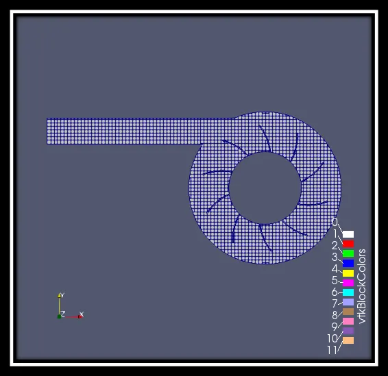
Surface with edges:
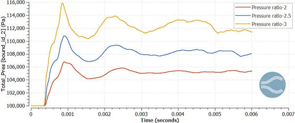
Pressure contours:
Pressure (2) - https://www.youtube.com/watch?v=WljBguP3uK0&feature=youtu.be
Pressure (2.5) - https://www.youtube.com/watch?v=BZmtxklEG6I&feature=youtu.be
Pressure (3) - https://www.youtube.com/watch?v=oZ8ATnSgOCM&feature=youtu.be
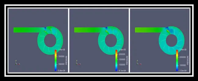
From the above, in all three cases the pressure enters at a high rate and when it reaches the casing the pressure drops gradually. After some point of time, the turbine blades get moved and the pressure value on the turbine blades will be relatively less.
Velocity contours:
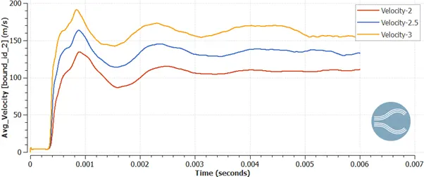
Velocity (2) - https://www.youtube.com/watch?v=FrkskPmc2MU&feature=youtu.be
Velocity (2.5) - https://www.youtube.com/watch?v=2lVjNtRLWH4&feature=youtu.be
Velocity (3) - https://www.youtube.com/watch?v=6WPBKRWNODg&feature=youtu.be
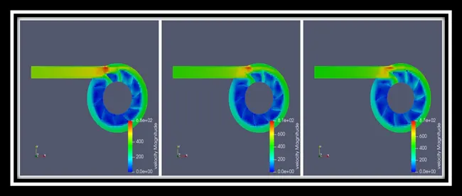
From the above, before the air enters into the casing the velocity rate is zero. Then after it enters the velocity gradually increases at the wall of the casing but, at the inner side of turbine blades the velocity is still zero because the air flow pushes the blades only at the edge side of it. When you see at particular edge side of a blade the velocity is relatively high since there is a pressure drop.
Rotational Velocity:
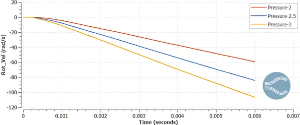
From the above graph, we came to know that if the pressure ratio increases the rotational velocity also increases and it shows that the simulation process is not get converged and it is still running. So, it is clear that 0.006 sec is not enough for converging process and in order to find out the end time of simulation we do some calculation with the help of rotational velocity value.
Take for instance if we select the pressure ratio of 2.5,
0.006 sec = 85 rad/sec
Convert into RPM
0.006 sec = 811.7 RPM
The turbine in the turbocharger spins at a speed of 150,000 RPM
0.006 sec = 811.7 RPM
x = 150,000 RPM
x = 1.1 sec
So if we want to make the process converge we have to run the simulation for 1.1 sec.
With the help of the above graph we can calculate the speed of RPM
|
PRESSURE RATIO |
SPEED IN rad/sec |
SPEED IN RPM |
|
2 |
60 |
573 |
|
2.5 |
85 |
811.7 |
|
3 |
105 |
1002.6 |
Mass flow rate:
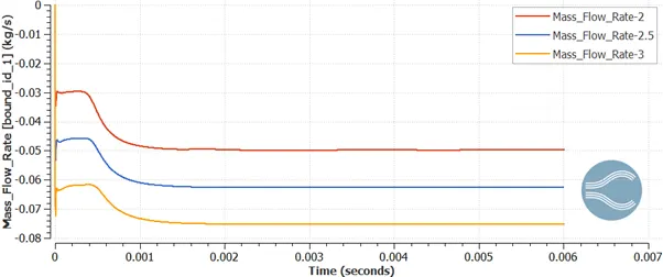
Inlet:
Outlet:
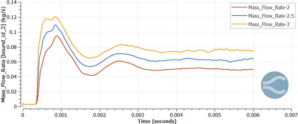
So when the pressure ratio increases the mass flow rate at both the inlet and outlet also increases.
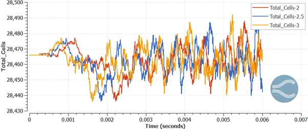
Total cell count:
CONCLUSION:
So, the simulation process for turbocharger is done for three different pressure ratios and from the results it is clear that the end time simulation must be increased in order to get it converged for a better result.