Tool Test-2
AIM:
For the given Intake Manifold component, check for the geometrical errors and mesh the Surfaces with the given 2D element Quality criteria given below.
|
S.No |
Quality Criteria |
Value |
|
1 |
Target/Average length |
3 |
|
2 |
Minimum Length |
1 |
|
3 |
Maximum Length |
5 |
Use tetra elements to mesh the Volumes defined in the model and check for the below quality after Volume meshing.
|
S.No |
Quality Criteria |
Value |
|
1 |
Tet collapse |
0.2 |
Write a detailed report on the same.
PROCEDURE:
The model to be worked on is an intake manifold and is shown below.
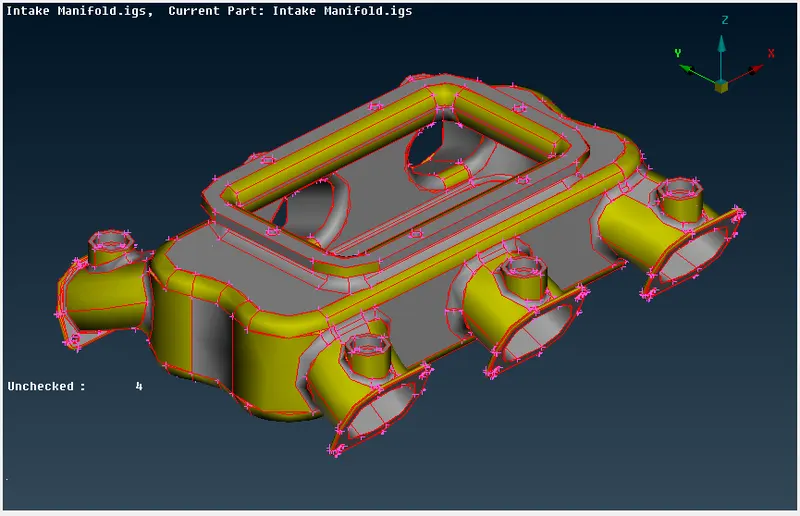
1. To check for geometry errors and conduct a geometry check.
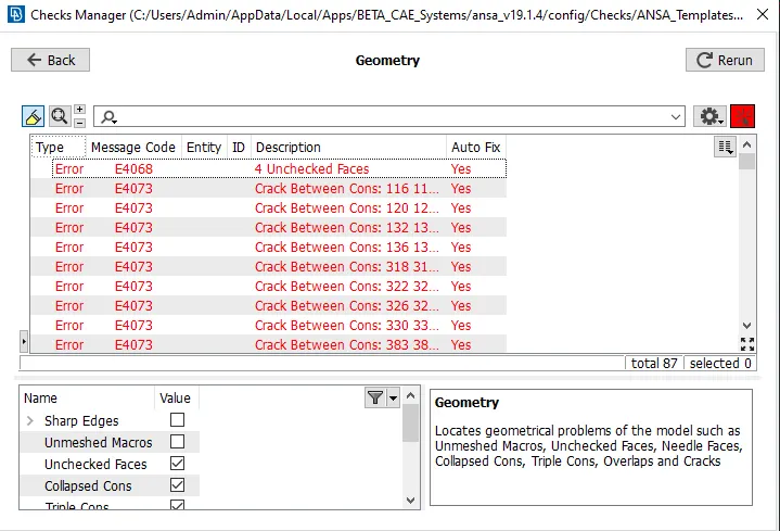
We do a geometry check on the model shown above by going to Tools->Checks->Geometry. We get a few errors as shown in the below image.
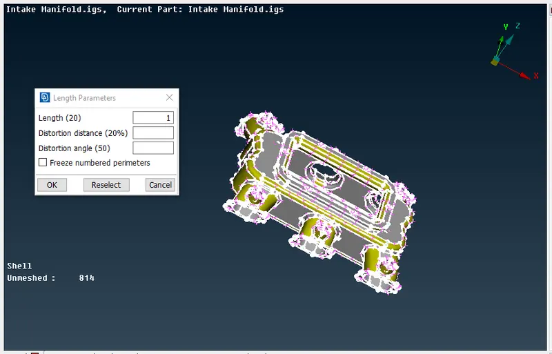
We need to set a perimeter and macro length for the model to check the accuracy of the design.
We fix the single cons issue by going to Topo module->Faces->Topo and then fix the orientation of the faces in the model by going to Topo module->Faces->Orient.
We then clean up the geometry so that it will be easier to mesh the surface. We remove unwanted hot points by going to Topo module ->Hot points->Delete and then remove unwanted feature lines by going to Topo module->Faces->Cut.
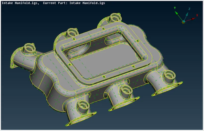
By doing all the above, we get an accurate model as shown below.
2. To give quality criteria and assign a mesh length
As per the requirement, we need to set the quality criteria and mesh parameters as shown below.
|
S.No |
Quality Criteria |
Value |
|
1 |
Target/Average length |
3 |
|
2 |
Minimum Length |
1 |
|
3 |
Maximum Length |
5 |
|
S.No |
Quality Criteria |
Value |
|
1 |
Tet collapse |
0.2 |
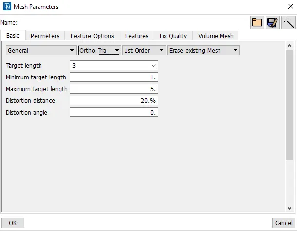
The mesh parameter is set as shown below. The target, minimum and maximum lengths are set along with the type of mesh (ortho tria) in the options.
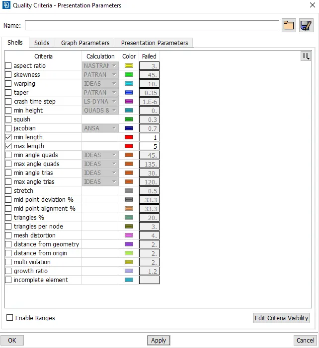
Next, we set the quality criteria for the model.
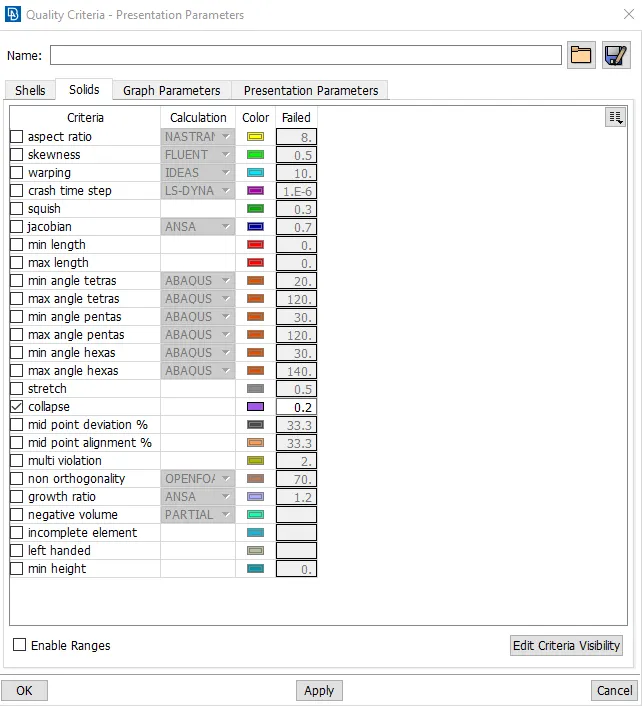
3. Now we need to mesh the surface with tria elements.
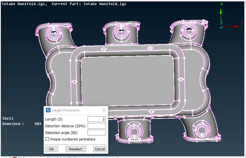
Before we start to mesh, we need to change the perimeter and macro length to the target length specified in the mesh parameters as shown in the image below.
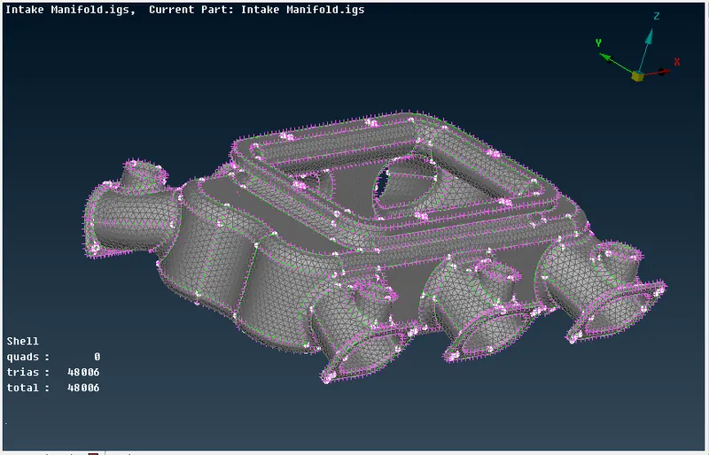
We do a geometry check and proceed after fixing all the errors. The meshing can be done by following Mesh module->Mesh generation->Spot mesh-> Select tria or ortho-tria. Ortho-tria mesh is used for curved features and tria mesh is used in less complicated areas. The meshed surface is shown below.
4. To solve all OFF elements for the meshed surface.
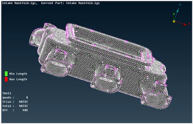
We can see from the above image that there are a total of 48232 trias and 403 of them are 'OFF' elements. We remove extra hot points by going to Mesh Module->Hot points->Delete or we can reconstruct the mesh at those places by going to Mesh module->Shell Mesh->Reconstruct.
The 'OFF' elements are shown in the images below.
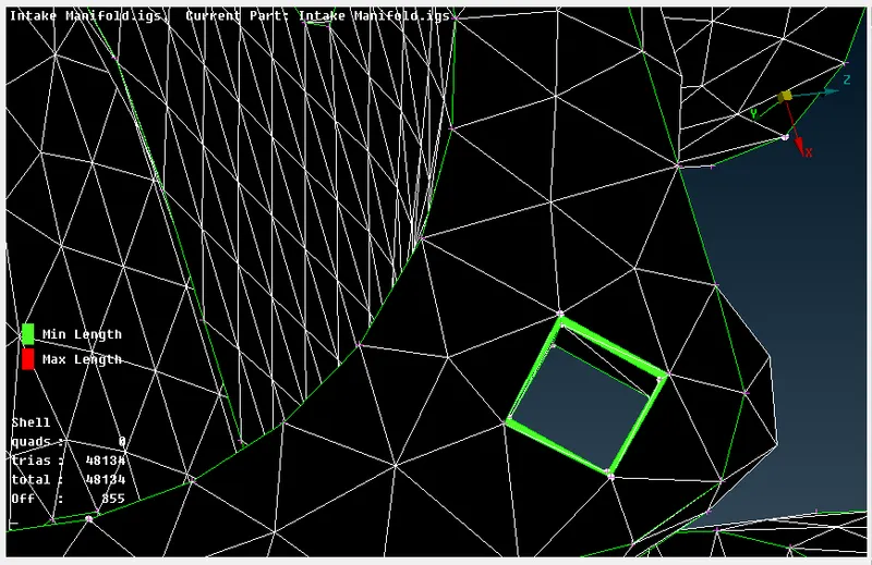
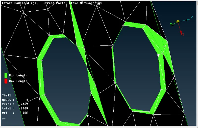
These elements at the fillet are failing for minimum length and can be fixed by defeaturing the fillets as it is of negligible length. We can do this by going to Mesh module->Macros->Join. We join the cons and remove the fillets in the model which solves the problem.
We will find some surface extensions on the model after the meshing as shown in the image below.
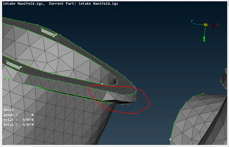
This can be fixed by going to Mesh module->Grids->Allign or we can go to Mesh module->Grids->MV free. Both these tools can help reduce the extension on the surface of the model.
After fixing all these failing elements, we get the model below.
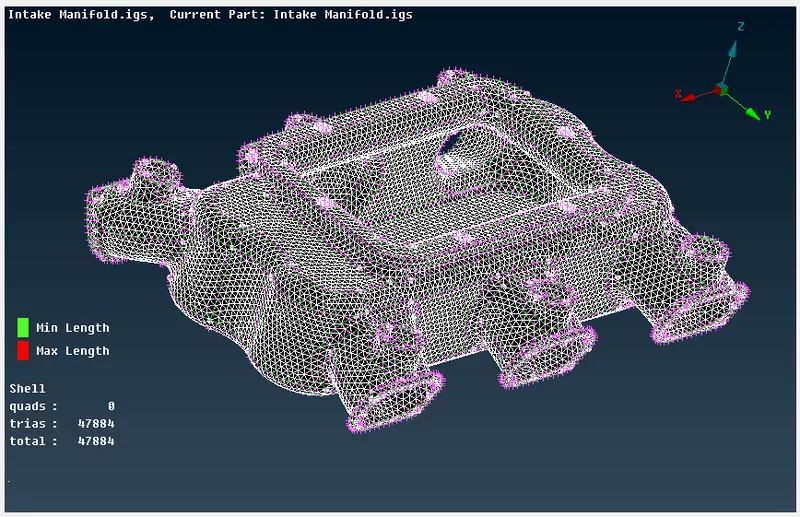
5. To define the volume in the volume mesh deck.
To define the volume, we go to Volume deck->Volumes->Define and then select 'Auto' to select the complete model. The property window opens up where we need to create a new
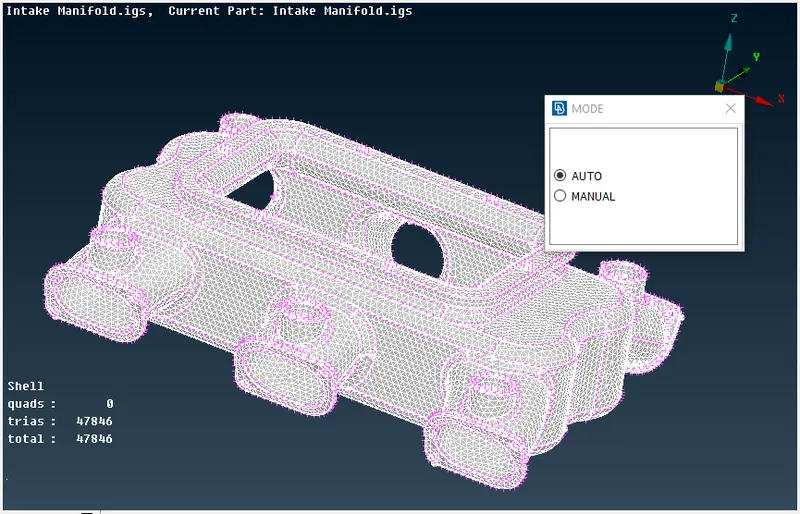
Once we confirm the selection, we need to create a 'PSOLID' property for the selected volume as shown in the image below.
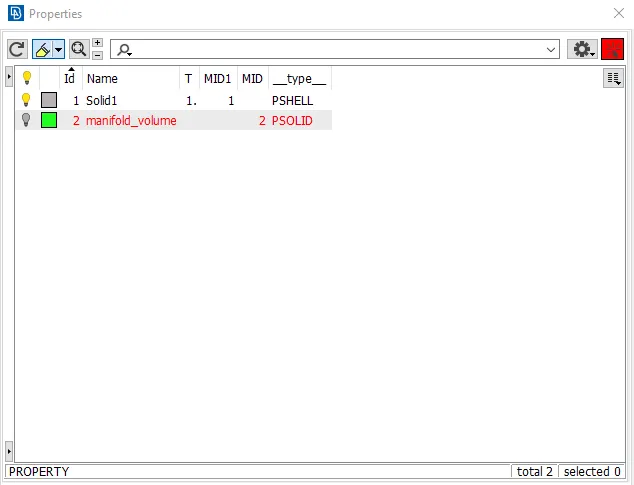
The 'PSOLID' property with the ID number 2 is named as 'manifold_volume' and now we define the volume once again so that we can find the same in the lists. To find it in the lists we need to go to Volume deck->Volumes->Lists and is shown in the image below.
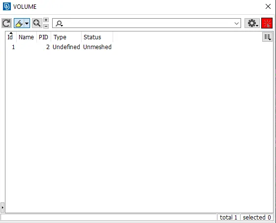
We can see in the above image that the status is shown as 'unmeshed' and the type is also shown as 'undefined'. This will be updated once we mesh the volume.
6. To mesh the volume with either Tetra Rapid or Tetra FEM algorithm.
We open the list, we name the volume that is stored in the list. Next, we right-click and select the type of mesh as shown below.
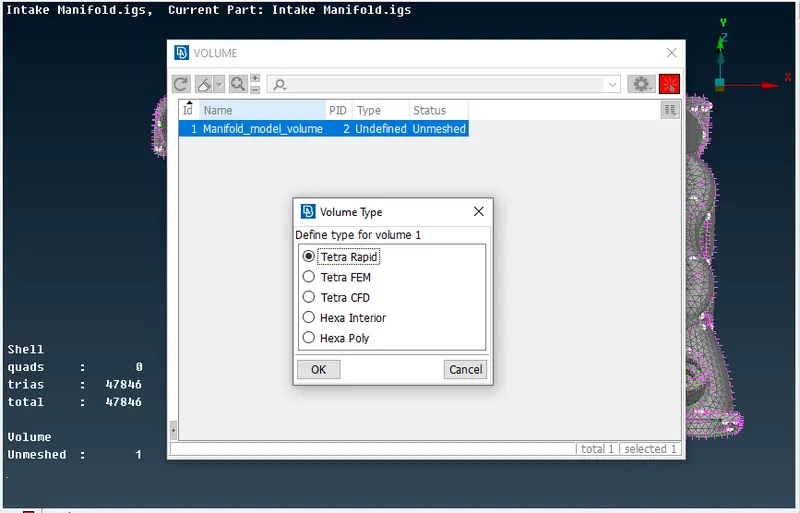
We have chosen the Tetra Rapid algorithm for the model. Once the algorithm is run, the volume mesh will be completed. The images are shown below.
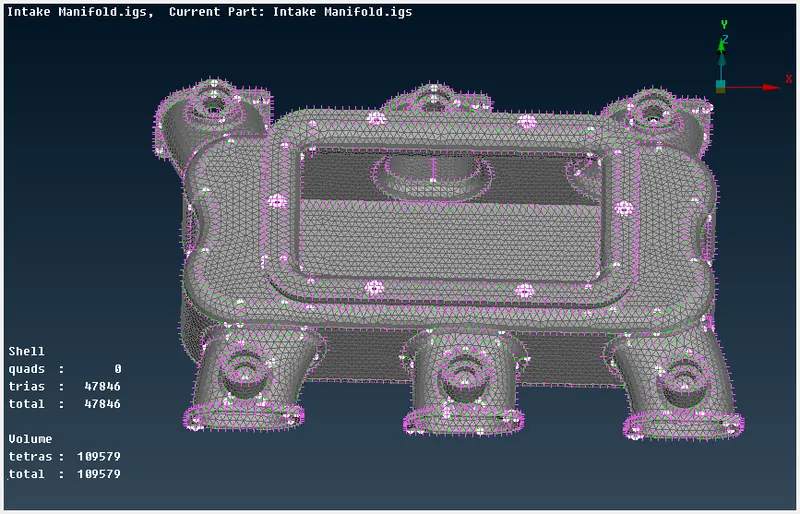
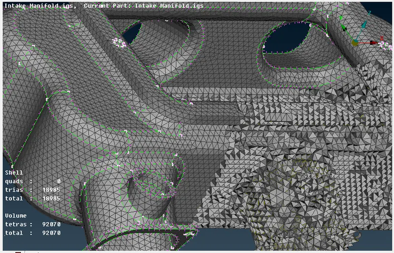
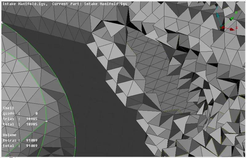
We can look into it and see the tetra mesh formed inside the surface as shown below.
7. To solve all the 'OFF' elements for volume meshed components with the given quality criteria.
When we check the quality criteria of the model after the volume mesh, we can find a few failed elements for 'tetra collapse' as shown in the image below.
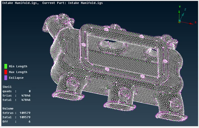
From the above image, we can see that there are a total of 47846 trias on the surface and the volume contains a total of 109579 tetras out of which 6 are 'OFF' elements. We need to fix these failing elements.
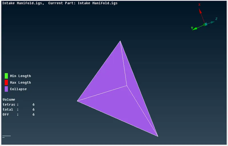
The above image shows us the tetra collapse in the volume.
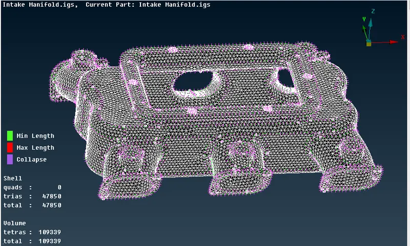
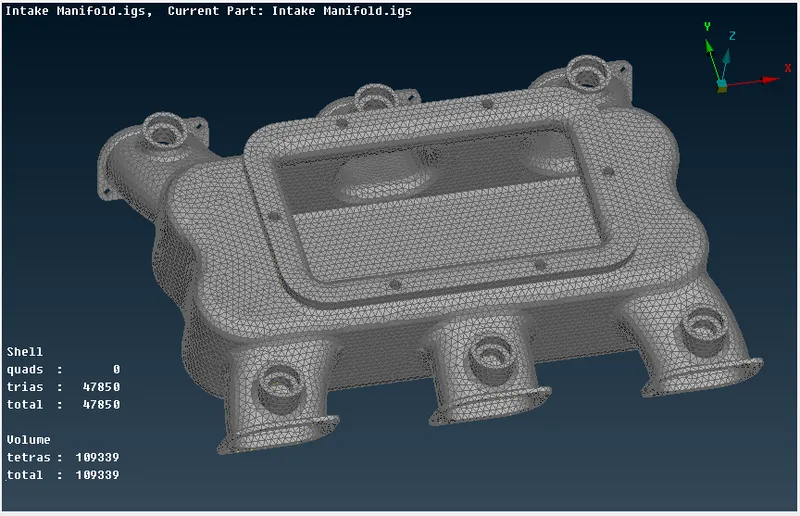
After fixing the Tetra collapse in the volume, we will get the final model as shown below.
CONCLUSION-
The geometry check has been run on the intake manifold model and the errors are fixed. The surface mesh has been created and all the 'OFF' elements are solved and fixed. The volume mesh type Tetra Rapid has been run on the volume of the model and all the failing elements have been fixed and solved. The model satisfies all the mesh parameters and the quality criteria.
The link to the model is given below.