Tool Test 1
For the given CAD model we have to check the geometrical errors and
create midsurface and mesh them with quality criteria. After meshing the
component thickness has to be assigned.
Quality Criteria:
|
S.No |
Quality Criteria |
Value |
|
1 |
Target/Average length |
4 |
|
2 |
Minimum Length |
2 |
|
3 |
Maximum Length |
6 |
|
4 |
Aspect |
3 |
|
5 |
Warpage |
15 |
|
6 |
Skewness |
45 |
|
7 |
Jacobian |
0.7 |
|
8 |
Minimum Quad Angle |
45 |
|
9 |
Maximum Quad Angle |
135 |
|
10 |
Minimum Tria Angle |
30 |
|
11 |
Maximum Tria Angle |
120 |
|
10 |
Tria Percentage |
15 |
PROCEDURE :-
MODEL - 1
In the ansa software firstly import the model.
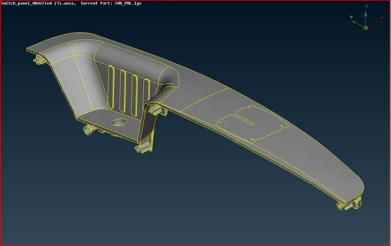
fig. Import Model
After that we gave a topo then orient the model.
Then check the geometrical check error.
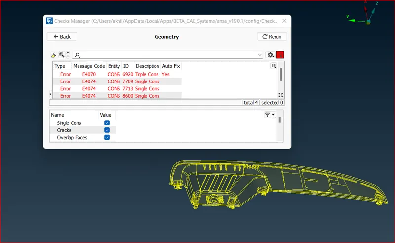
fig. Geometry checking
After the checking we got error then we fixed the error.
Then we got,
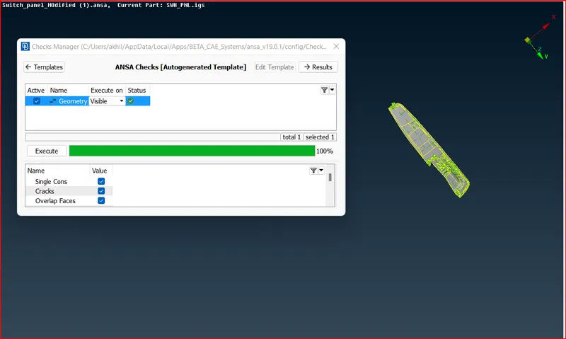
fig. Error Fixed
Then we midsurfacing this model.
Midsurface is the process of extracting the skin of the component according to the
thickness of the component.
This component having various thickness in geometry.
We need to measure all critically areas and taking midsurface according to the offset and middle.
using the curve middle for projection the midsurface in the geometry.
Each and every part of the component is taking the midsurface as per the thickness.
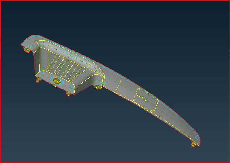
fig. midsurface of model
After the midsurfacing the model then we go for the meshing.
Before meshing put the value in mesh parameter and quality criteria.
After the fill this then go for the meshing.
After meshing quality criteria fails for that we have to used split and paste,
then smooth tab.
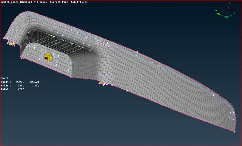
fig. Mesh part
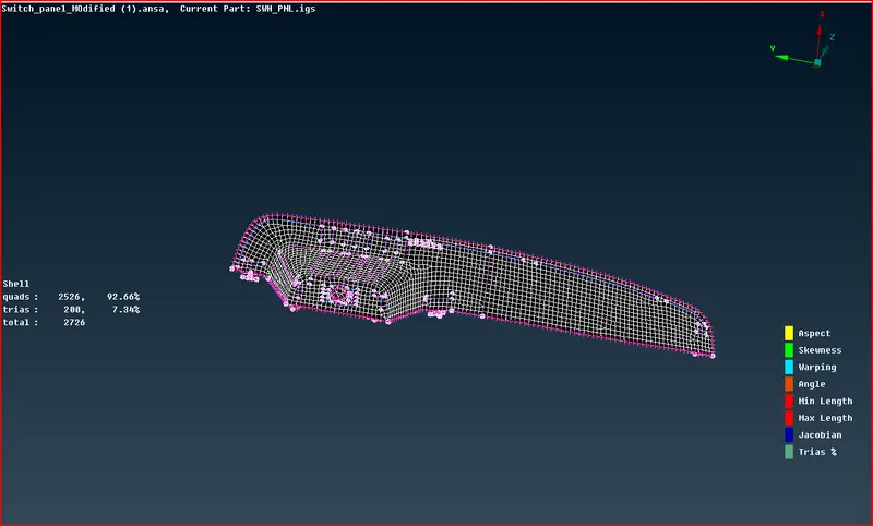
fig. Quality Criteria
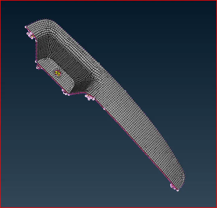
fig. Draw shell as solid
MODEL - 2
Firstly import the model.
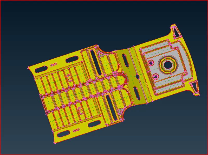
fig. Import model
After that geometry check.
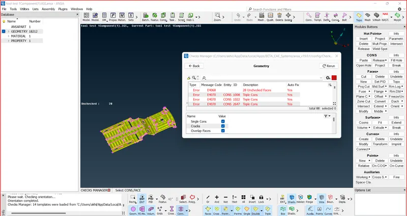
fig. Geometry check
Geometry After cleaning all the geometrical errors.
We got some errors in the model then fix them.
After the fix error we got,
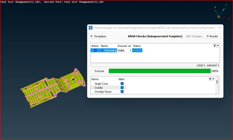
fig. Cleaning geometrical errors
Then, midsurfacing the model,
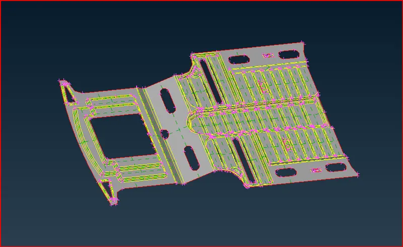
fig. midsurface of the model
Then we go to the meshing.
Before meshing put the value of mesh parameter and quality criteria.
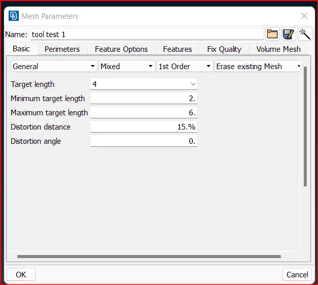
fig. Mesh Parameter
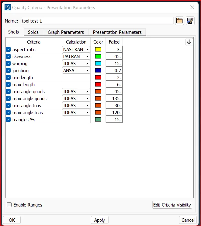
fig. Quality Criteria
Then, After that mesh the model using Best tab.
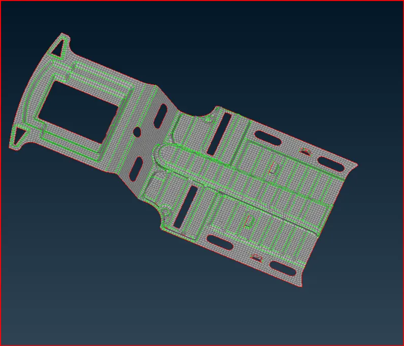
fig. Mesh part
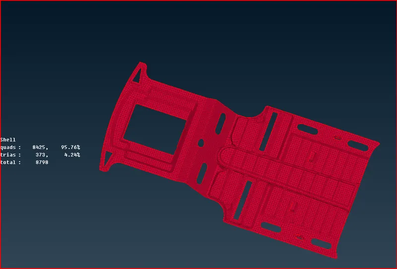
fig. quality criteria
Final Meshed Geometry
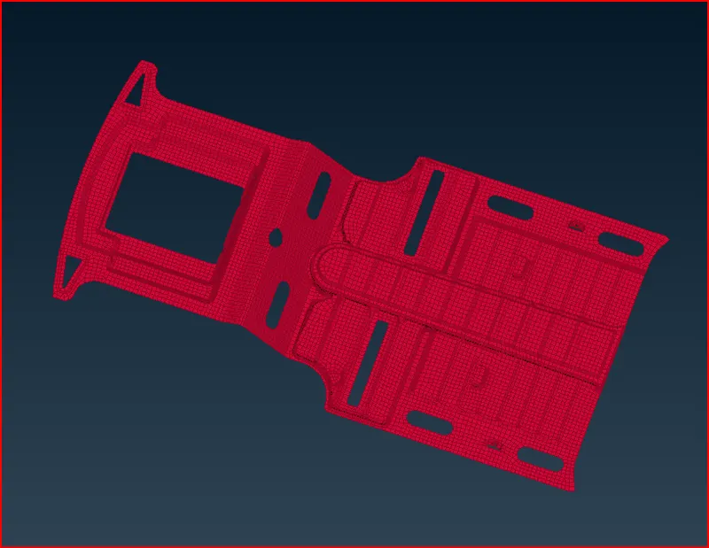
fig. Final Image
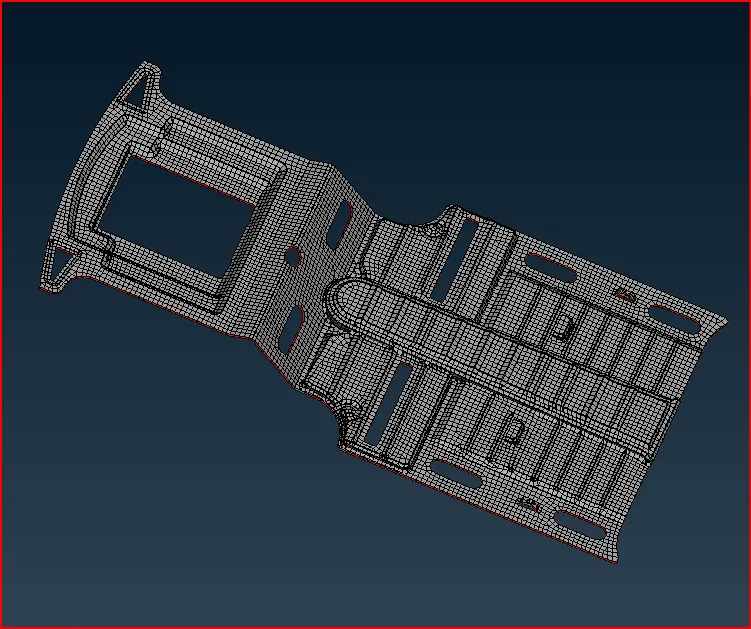
fig. Draw shell as solid
Conclusion :-
We have meshed the model.
To understand the Midsurfacing and meshing of given components and also checked
geometry cleanup of component.