Tool Test 1
AIM -
This tool test carries two models (i.e. Plastic model, Sheet metal model). For both the models, Mid surface should be taken and meshed as per the below quality criteria. The thickness should be assigned to both models. (Refer to “Model Requirements” in “Grading Policy” to know what to be done in the model)
Quality Criteria:
|
S.No |
Quality Criteria |
Value |
|
1 |
Target/Average length |
4 |
|
2 |
Minimum Length |
2 |
|
3 |
Maximum Length |
6 |
|
4 |
Aspect |
3 |
|
5 |
Warpage |
15 |
|
6 |
Skewness |
45 |
|
7 |
Jacobian |
0.7 |
|
8 |
Minimum Quad Angle |
45 |
|
9 |
Maximum Quad Angle |
135 |
|
10 |
Minimum Tria Angle |
30 |
|
11 |
Maximum Tria Angle |
120 |
|
10 |
Tria Percentage |
15 |
PROCEDURE -
MODEL - 1 - SWITCH PANEL
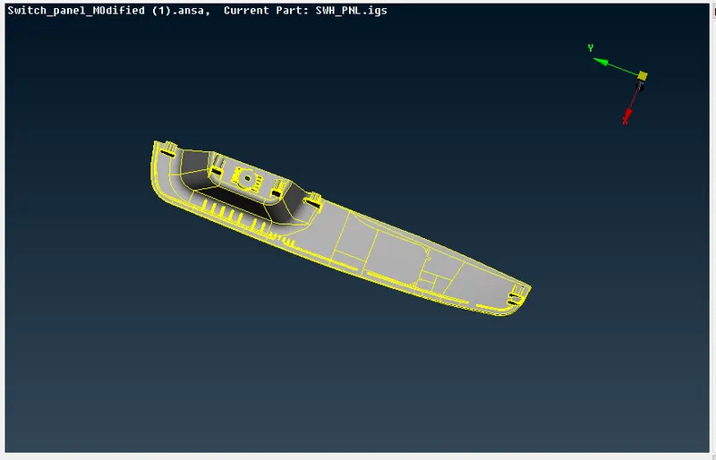
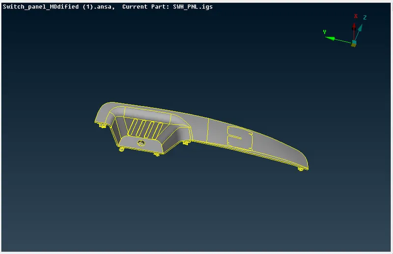
The model to be worked on is shown in the below image.
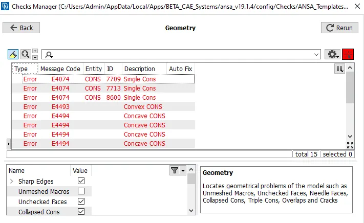
1. The first step is to do the geometry check for the entire model. We go to Tools->Checks->Geometry and verify the validity of the model. If there are any errors in the model, it can be auto-fixed and verified again as shown in the image below.
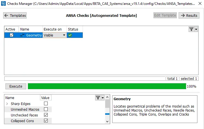
Once the errors are auto-fixed, the checks can be re-run and the result is as shown below.
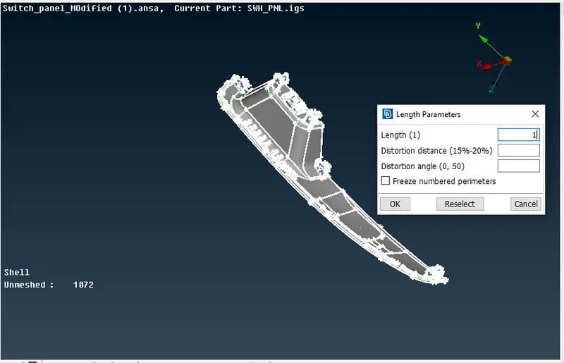
2. The second step is to set the perimeter and the macro length of the model to 1 to increase the resolution and clarity of the model features. We go to Mesh->Perimeters->Length and select the model and set the value.
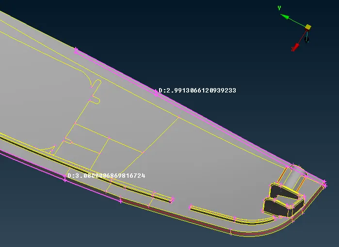
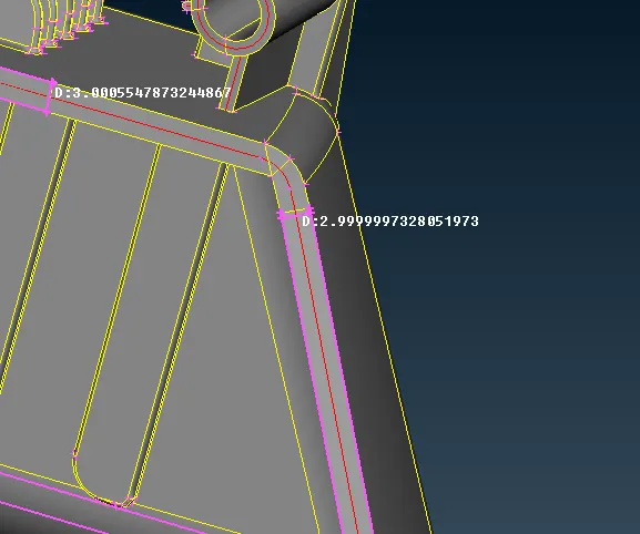
3. After the geometry cleanup and setting up the perimeter length for the model, we measure the thickness to determine the offset value. We measure thickness at various places in the model. We go to utilities->Measure->Select the cons/curves.
4. With this we will start to take out the mid-surface for the model. We can use the offset tool by going to Topo->Faces->Offset and give the required value, or we can use the middle option in Topo->Faces->Middle (single or multi depending on the surfaces). We can also create mid-curves by going to Topo->Curves->Middle and then create new surfaces which can be considered a mid-surface.
New surfaces can be created by going to Topo->Faces->New surface (We can choose coons, fitted, planar or existing surface accordingly). The major mid-surface areas obtained from the model are shown below.
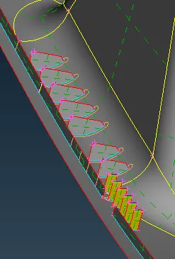
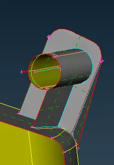
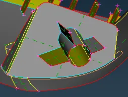
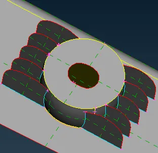
We use the middle option and the offset to take out the mid-surfaces and then extend the surfaces to their parent mid-surface. The red curves are single cons, yellow curves are the double cons, blue curves are the triple cons as shown in the image below.
The below images are some of the important features of the model.
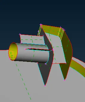
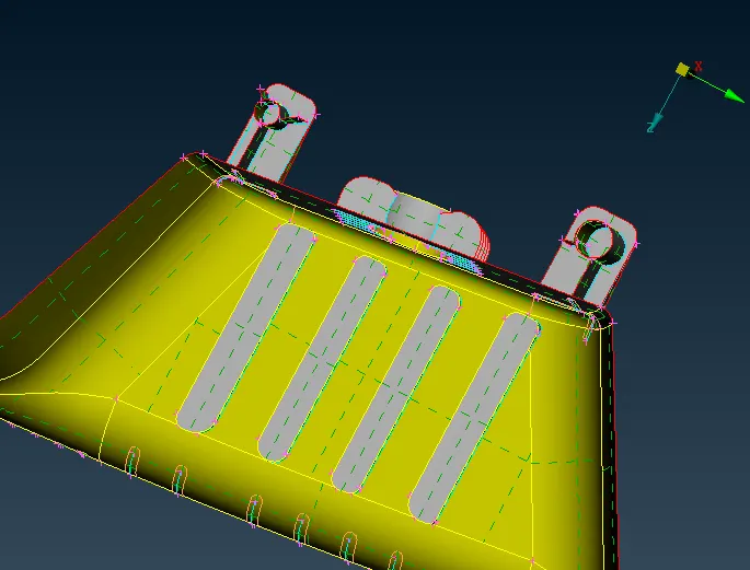
The final mid-surface of the model is shown below.
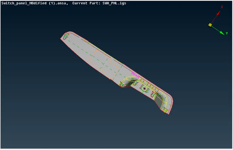
5. After obtaining the mid-surface we move onto the meshing process.
First, we set the mesh parameters as per the requirement. We go to utility ->Mesh parameters and add the given values as shown
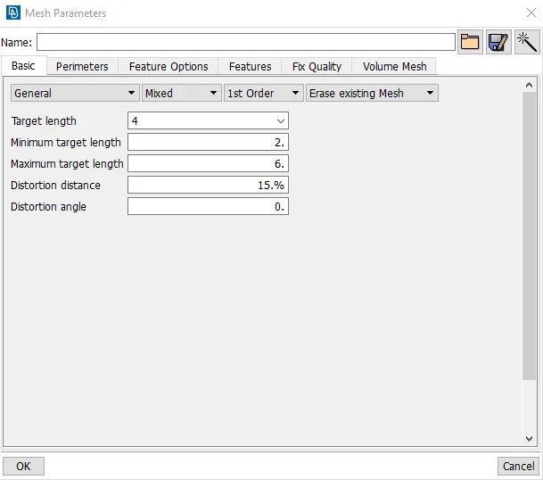
After this, we set the quality criteria for the mesh. We go to utilities->Quality criteria and set the given parameters.
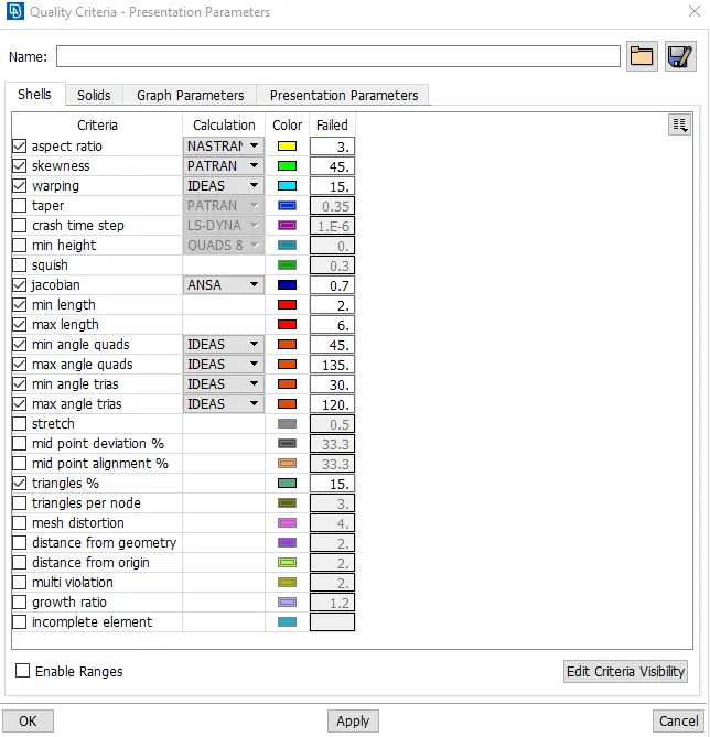
Now we change the perimeter and macro length of the model to its target length which is 4 in our case. We check for geometrical errors using the geometry checks tool as before and fix any issues which have occurred. Now, we can proceed with the meshing by using the Mesh->Mesh generation->Best to generate the best possible mesh for the given model. The meshed model is shown below.
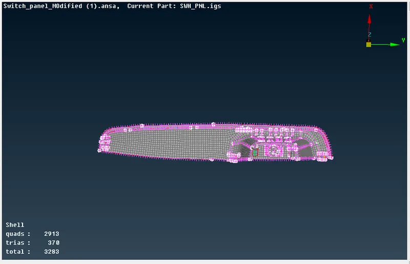
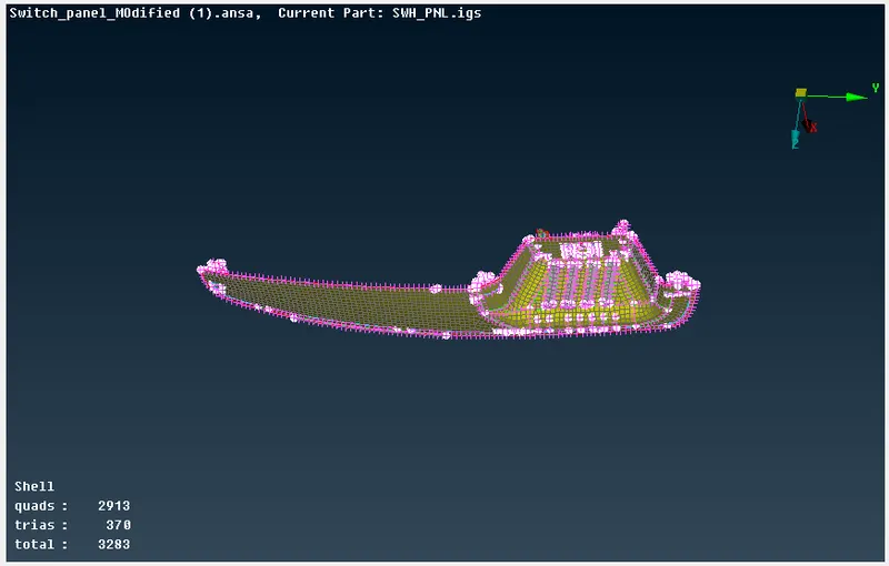
We use tools like split, paste, swap to re-arrange the trias away from the edges and reduce the numbers and then use tools like smooth and reconstruct to re-mesh the required areas to obtain the best mesh for the model.
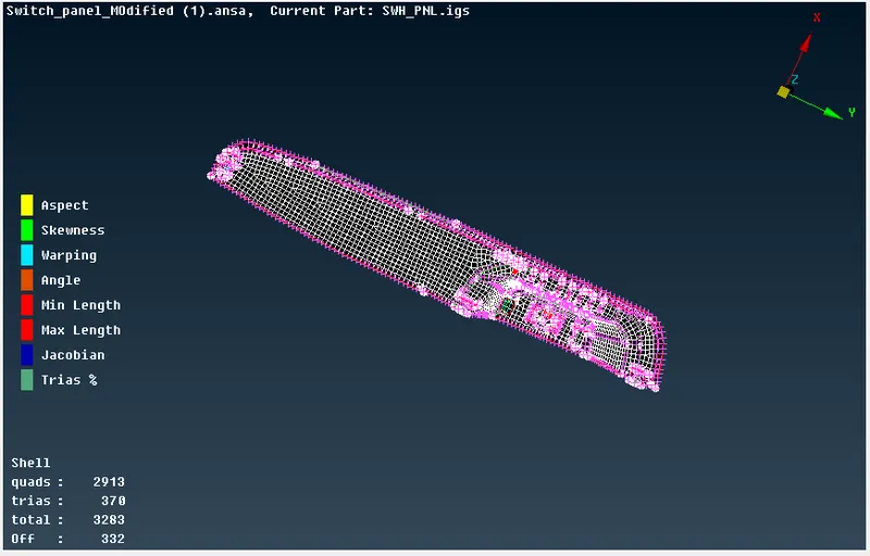
The elements neat the triple cons fail required quality criteria, but we keep it to the minimal.
MODEL - 2
The model to be worked on is shown in the below image.
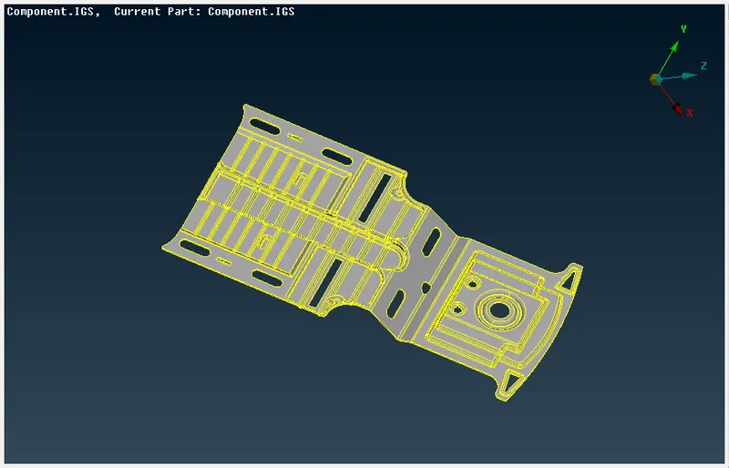
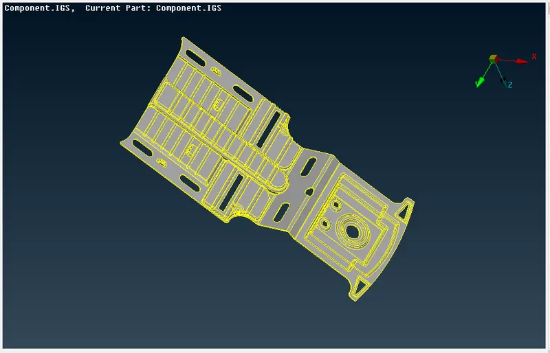
1. The first step as explained above is to do the geometry check for the entire model. We go to Tools->Checks->Geometry and verify the validity of the model. If there are any errors in the model, it can be auto-fixed and verified again as shown in the image below.
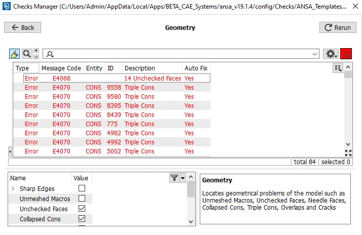
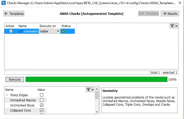
Once the errors are auto-fixed, the checks can be re-run and the result is as shown below.
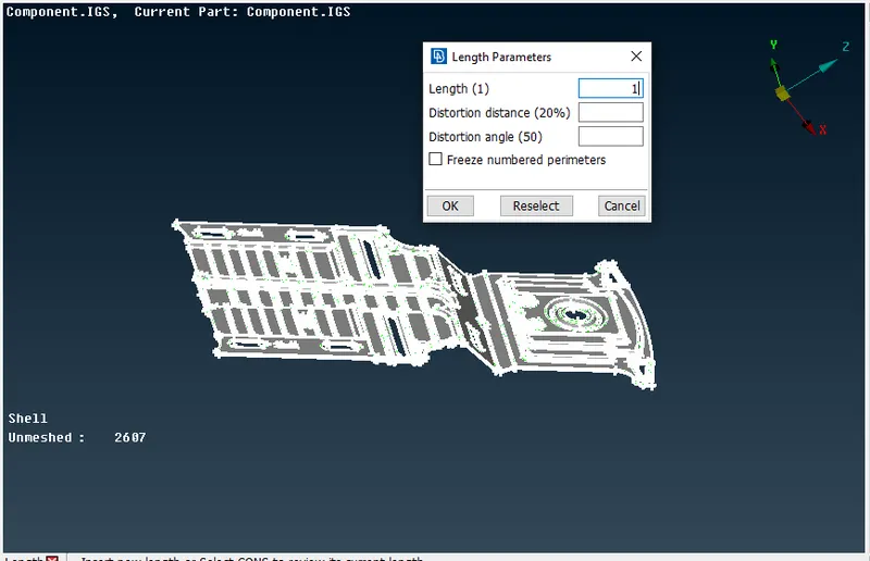
2. The second step again as explained in the previous model is to set the perimeter and the macro length of the model to 1 to increase the resolution and clarity of the model features. We go to Mesh->Perimeters->Length and select the model and set the value.
3. After the geometry cleanup and setting up the perimeter length for the model, we measure the thickness to determine the offset value. We measure thickness at various places in the model. We go to utilities->Measure->Select the cons/curves.
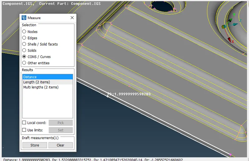
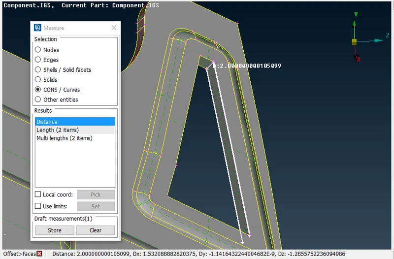
4. With this we will start to take out the mid-surface for the model. We can use the offset tool by going to Topo->Faces->Offset and give the required value, or we can use the middle option in Topo->Faces->Middle (single or multi depending on the surfaces). We can also create mid-curves by going to Topo->Curves->Middle and then create new surfaces which can be considered a mid-surface.
New surfaces can be created by going to Topo->Faces->New surface (We can choose coons, fitted, planar or existing surface accordingly). The major mid-surface areas obtained from the model are shown below.
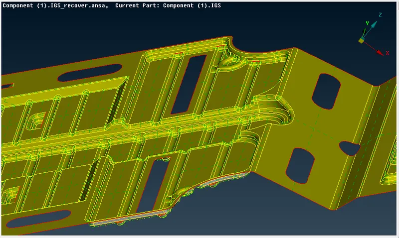
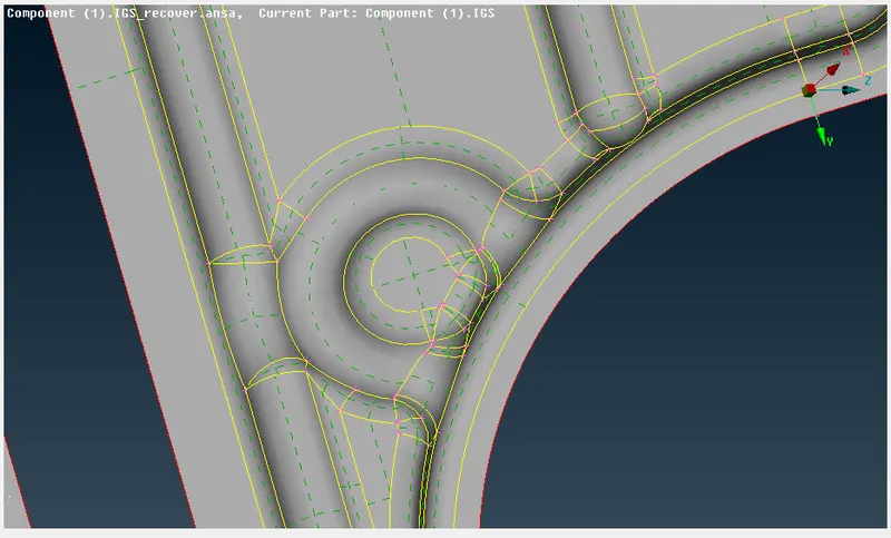
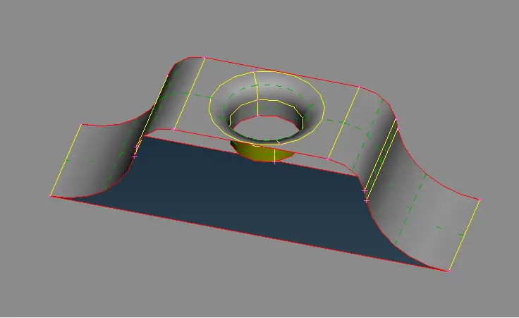
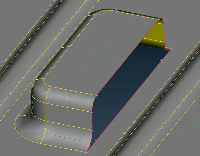
We use the middle option and the offset to take out the mid-surfaces and then extend the surfaces to their parent mid-surface. The red curves are single cons, yellow curves are the double cons, blue curves are the triple cons as shown in the image below.
The below images are some of the important features of the model.
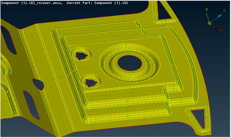
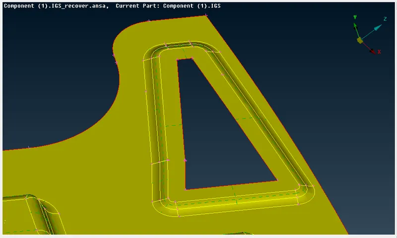
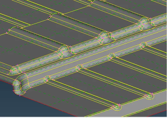
The final mid-surface of the model is shown below.
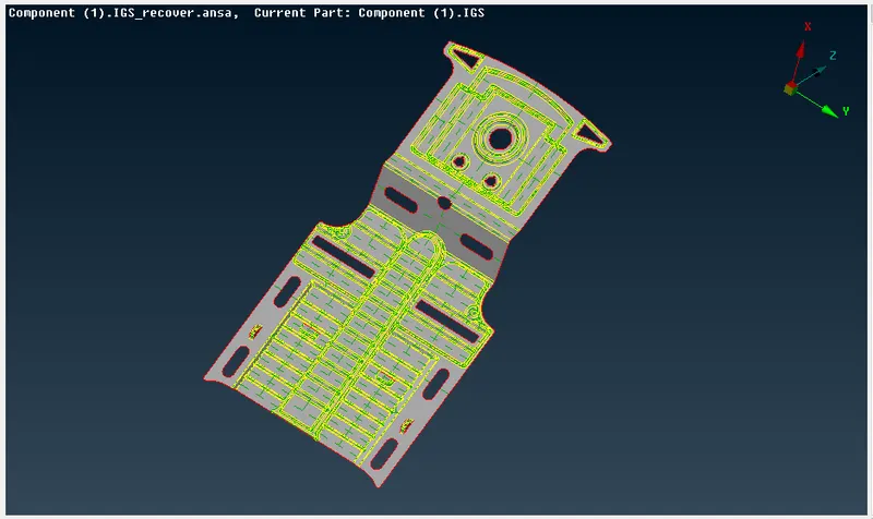
5. After obtaining the mid-surface we move onto the meshing process.
First, we set the mesh parameters as per the requirement. We go to utility ->Mesh parameters and add the given values as shown
After this, we set the quality criteria for the mesh. We go to utilities->Quality criteria and set the given parameters.
Now we change the perimeter and macro length of the model to its target length which is 4 in our case. We check for geometrical errors using the geometry checks tool as before and fix any issues which have occurred. Now, we can proceed with the meshing by using the Mesh->Mesh generation->Best to generate the best possible mesh for the given model. The meshed model is shown below.
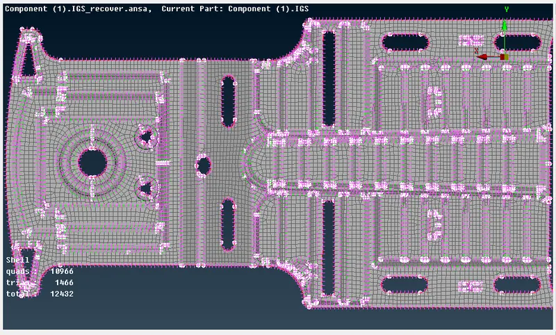
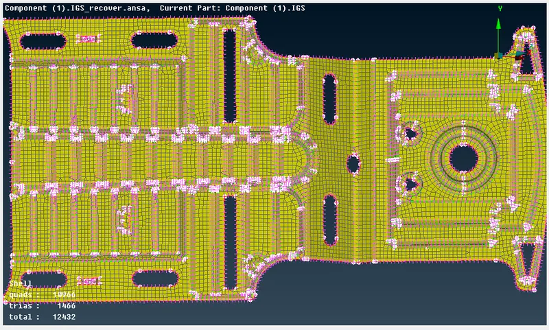
We use tools like split, paste, swap to re-arrange the trias away from the edges and reduce the numbers and then use tools like smooth and reconstruct to re-mesh the required areas to obtain the best mesh for the model.
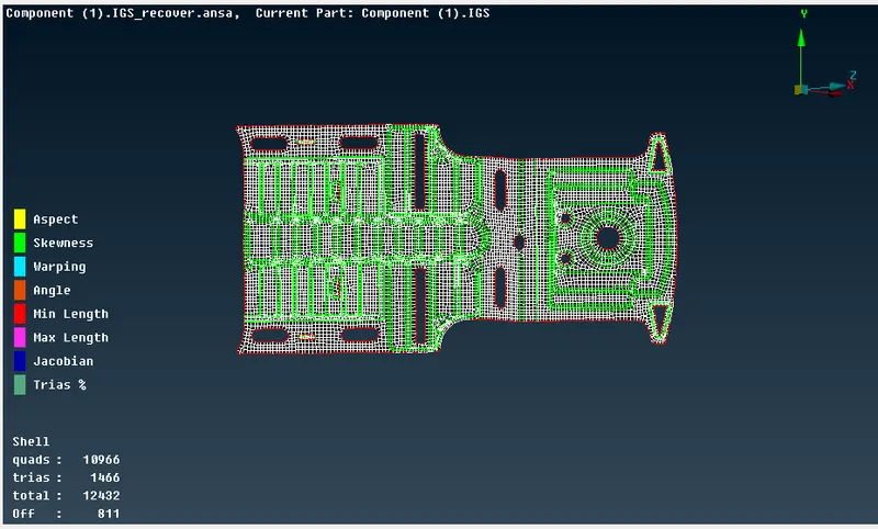
The elements neat the triple cons fail required quality criteria, but we keep it to the minimal.
CONCLUSION -
The mid-surfaces of the given two models are obtained successfully and meshed as per the mesh parameters and quality criteria. The number of trias and the failed elements near the triple cons is maintained at a minimum. The models are attached in the below links.