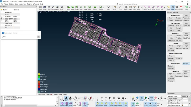
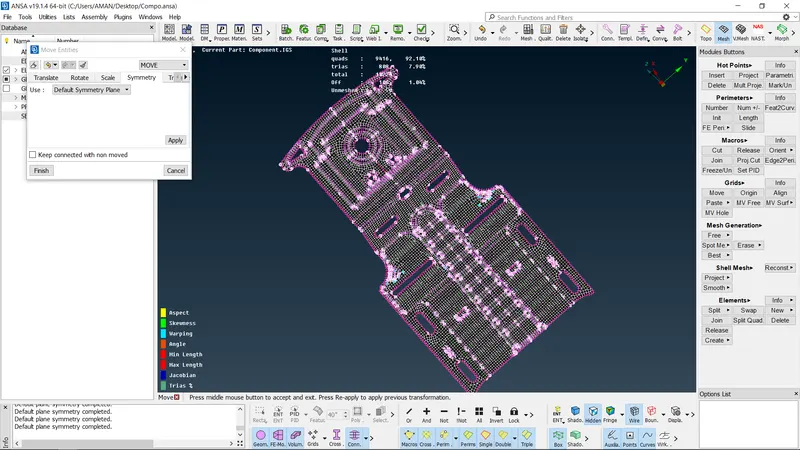
Tool Test 1
Objectives:
- The objective of this project is to performing meshing for Tool test 1 for component1 & Component 2 using the ANSA tool
- From the given Component, Checking geometrical errors and mesh with given element quality criteria
- Extracting the mid surface from the component.
- After meshing the component the thickness has to be assigned
-
- FE meshes are better representations of their geometric parents Also, it is easy to maintain and update any changes in the geometry by simply reworking the updated area instead of recreating the FE from scratch
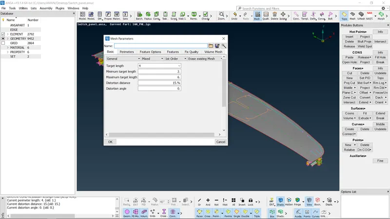
- Switching to the Mesh mode and we need to give the shell element size length according to the given input -4mm.
- For getting the smooth mesh we need to segregate the surface to various cut regions
- Before Meshing we need to clean up the Some Geometry error also then only the flow of mesh should be smooth
- While Meshing we need to maintain the quality criteria then only we will get the
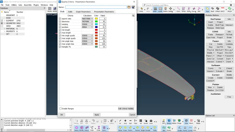
6 We need to set up the mesh Parameters as will as presentation parameters according andino painbai to given inputs.
7 In the Mesh pararmeters, we are giving the target length with minimum and maximum
- In the presentation parameters, we need to enable Elements (%) and details on the Demand effect should be all details.
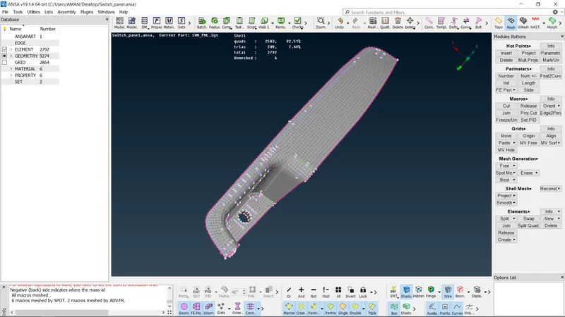
- In the Mesh Generation, we need to give the Free or Best mesh as per the Mesh flow.
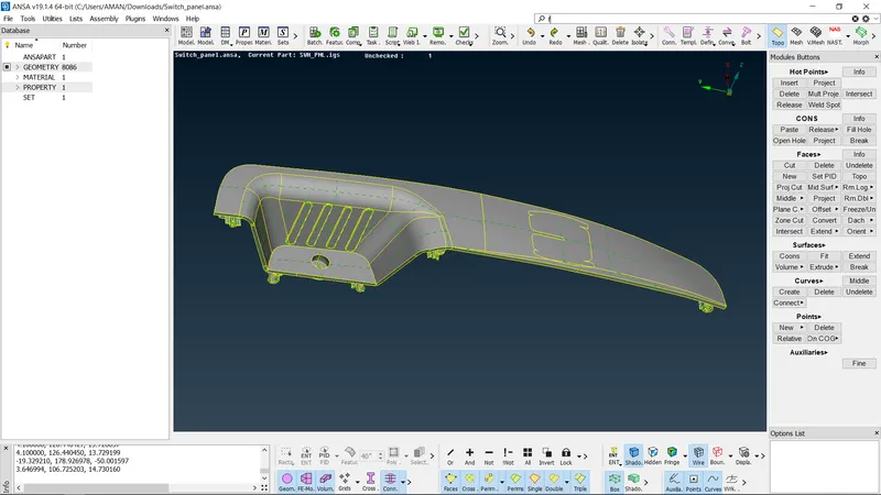
check the comp.
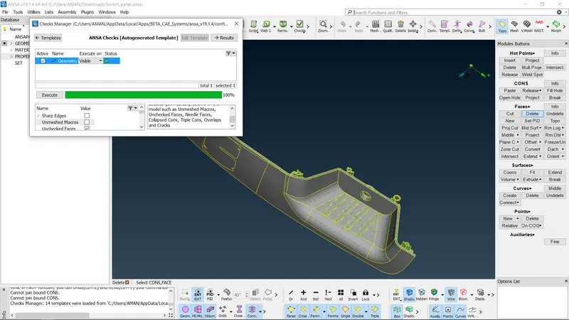
after check the find the error
- The geometry checks are used to check the geometry setup file using checkbox by selecting the geometry option
- And it shows that various errors in the geometry on the surface
- After that need to surfacing cleaning is done.
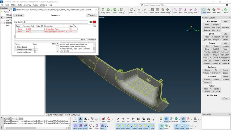
Surface Cleaning
- Surface Cleaning is the process of clean up the surface error
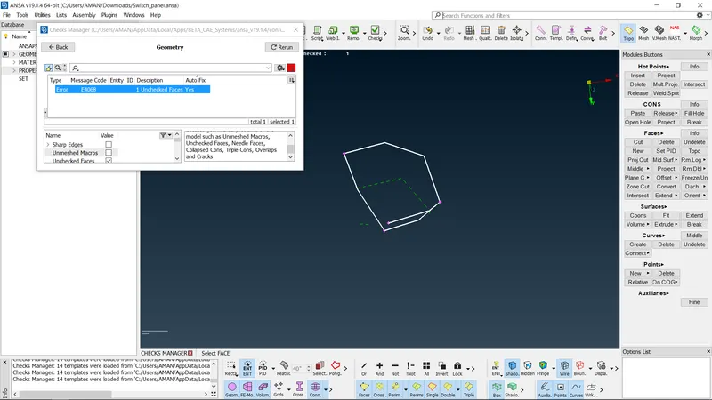
- An error such as holes. Extra surface, single cones. Crack
- Single cones are used to clean up using the Select the all with Topology method
- Some of the tools used to fix the problem are coons surface patch, Fill holes, New for the Faces. Foxing Cracking
- After selecting the particular area on that surface are missing like that using the tools to patch the area with select after that clicking the middle mouse bottomn
- In the surface cleaning methods. Ansa tools itself giving the Autofix for the some of the Error takes place in the model
- Further open edges and single cons are in the geometry are corected using the topo
Midsurface:
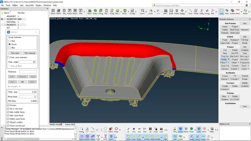
- Midsurface is the process of Extracting the skin of the component according to the thickness of the Component.
- This component having the Various thickness in geometry
- We need to measure all critically area and taking Midsurface according to the Offset and Middle.
- Using the Curve middle for projection the midsurface in the geomentry
- In the topo mode, extracting the mid surface by Faces option in that Offset we need to select.
- After selecting the offset we need to select the surface its shows the direction of the arrow.
- If upwards indicates means we need to give value in negative it's vice versa
- A red color line indicates the mid surface take in the component
Property Id:
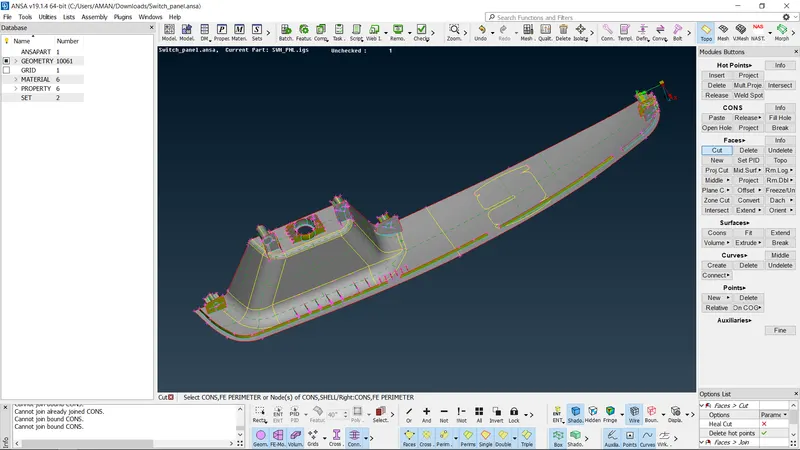
Property id is the process in which after the mid surface has taken we need to assign the Property to the surface with thickness
- FE meshes are better representations of their geometric parents Also, it is easy to maintain and update any changes in the geometry by simply reworking the updated area instead of recreating the FE from scratch
- Switching to the Mesh mode and we need to give the shell element size length according to the given input -4mm.
- For getting the smooth mesh we need to segregate the surface to various cut regions
- Before Meshing we need to clean up the Some Geometry error also then only the flow of mesh should be smooth
- While Meshing we need to maintain the quality criteria then only we will get the
6 We need to set up the mesh Parameters as will as presentation parameters according andino painbai to given inputs.
7 In the Mesh pararmeters, we are giving the target length with minimum and maximum
- In the presentation parameters, we need to enable Elements (%) and details on the Demand effect should be all details.
- In the Mesh Generation, we need to give the Free or Best mesh as per the Mesh flow.
final product
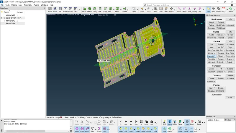
- Importing the componentl-switch panel stp.file to the Ansa toolbar.
Geometry Checks:
- The geometry checks are used to check the geometry setup file using checkbox by selecting the geometry option
- And it shows that various errors in the geometry on the surface
- After that need to surfacing cleaning is done.
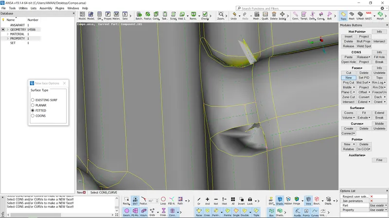
Surface Cleaning
- Surface Cleaning is the process of clean up the surface error
- An error such as holes. Extra surface, single cones. Crack
- Single cones are used to clean up using the Select the all with Topology method
- Some of the tools used to fix the problem are coons surface patch, Fill holes, New for the Faces. Foxing Cracking
- After selecting the particular area on that surface are missing like that using the tools to patch the area with select after that clicking the middle mouse bottomn
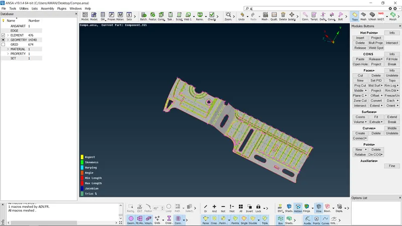
Midsurface:
- Midsurface is the process of Extracting the skin of the component according to the thickness of the Component.
- This component having the Various thickness in geometry
- We need to measure all critically area and taking Midsurface according to the Offset and Middle.
- Using the Curve middle for projection the midsurface in the geomentry
- In the topo mode, extracting the mid surface by Faces option in that Offset we need to select.
- After selecting the offset we need to select the surface its shows the direction of the arrow.
- If upwards indicates means we need to give value in negative it's vice versa
- A red color line indicates the mid surface take in the component
- After Extracting the mid surface we need to assign the PID region with thickness.
- Each and every part of the component is taking the mid surface as per the thickness
- For the outer wall and inner wall offsetting as per a thickness
- For every fines and inner thread are.offsetting with the help of Faces Middle and Offset.
- In the Topo mode itself, we will be clearing all the Geometry cleanup.
Property Id:
Property id is the process in which after the mid surface has taken we need to assign the Property to the surface with thickness
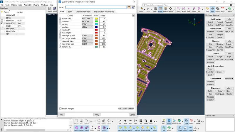
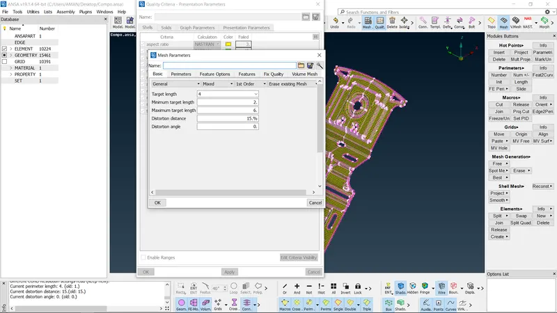
Meshing.
- FE meshes are better representations of their geometric parents Also, it is easy to maintain and update any changes in the geometry by simply reworking the updated area instead of recreating the FE from scratch
- Switching to the Mesh mode and we need to give the shell element size length according to the given input -4mm.
- For getting the smooth mesh we need to segregate the surface to various cut regions
- Before Meshing we need to clean up the Some Geometry error also then only the flow of mesh should be smooth
- While Meshing we need to maintain the quality criteria then only we will get the
6 We need to set up the mesh Parameters as will as presentation parameters according andino painbai to given inputs.
7 In the Mesh pararmeters, we are giving the target length with minimum and maximum
- In the presentation parameters, we need to enable Elements (%) and details on the Demand effect should be all details.