To plan a structural layout and to create grids using TSD
1)Summarize the user interface in TSD with the for the following items: -
Project Workspace – How to access and usage
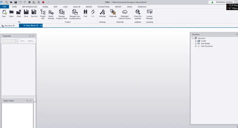
- First open the tekla structures sofware GO TO FILE TAB
- click on the new option it will automatically create a work space for the new project.
Scene Content – Demonstrate the use of scene content
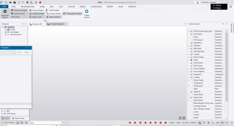
- GO to the windows tab and click on the scene content it creates the sence content tab .
- it would be very use ful tomodeling the structure to view and select the different kind of elements with in the filter.we can set what we wish to visible in the windows space.
Create two scene views
- the sence views are already created when we click on the new option this will use to view the model in 2D and 3D views.
Loading drop list- How to access
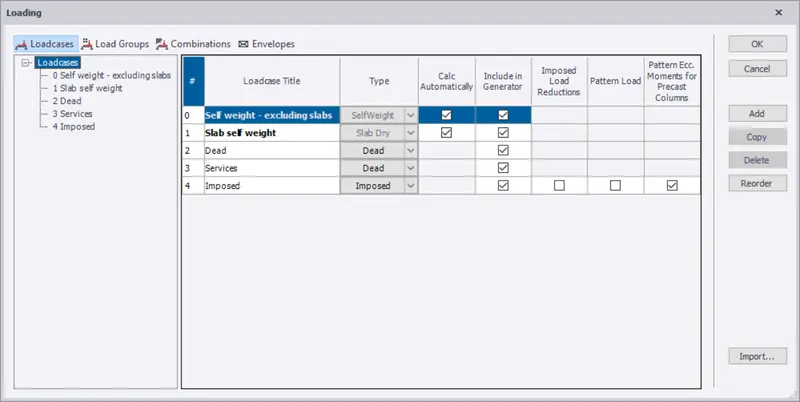
- go to load tab u can acees the related to loading.
Properties windows – how to access and usage
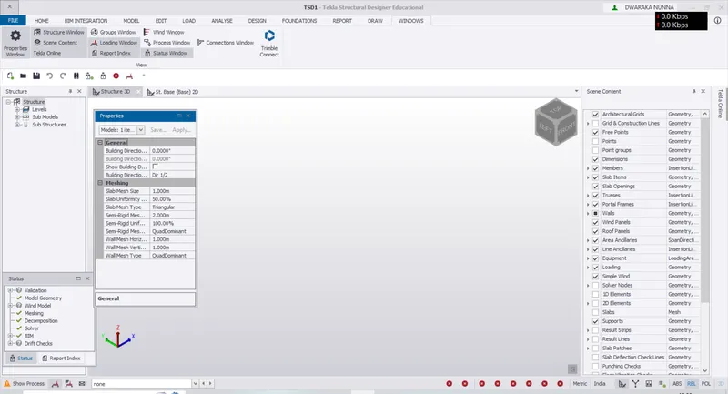
- open the windowa tab from there we acan access the properties tab.
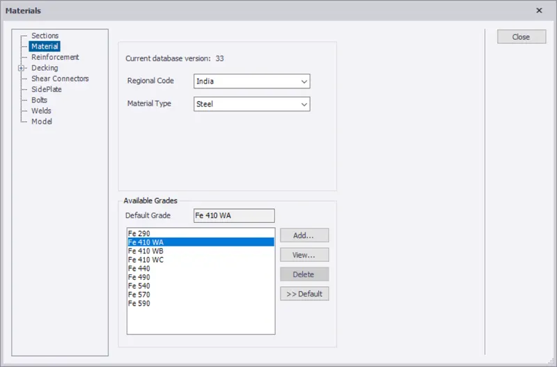
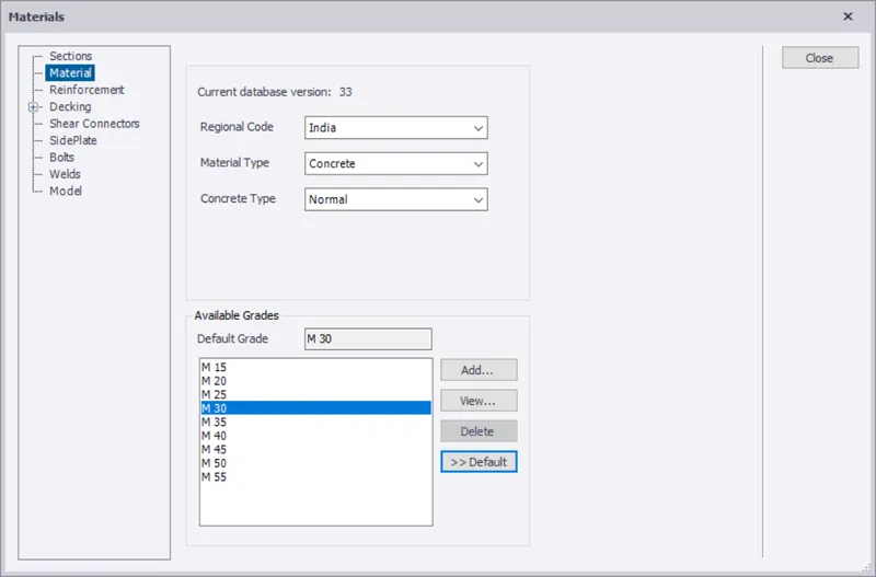
2. Create a new file in TSD and set up the settings for a steel building to have member grade FE410 and concrete grade of M30 as per IS codes.
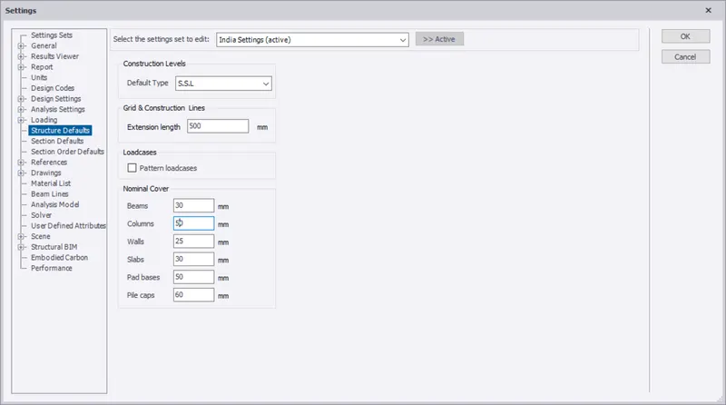
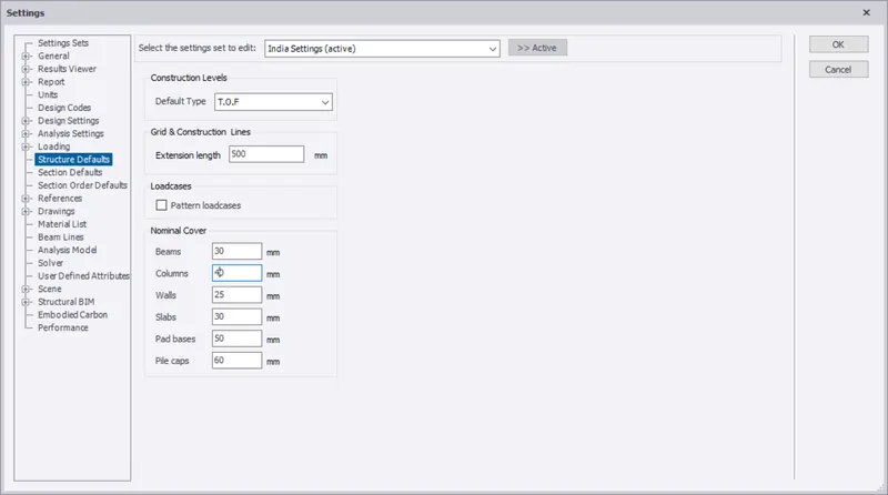
The covers for the members to be as per the following input: -
|
MEMBERS |
IN CONTACT WITH GROUND |
ABOVE GROUND |
|
Column |
50mm |
40mm |
|
Slab |
30mm |
25mm |
|
Pile cap |
75mm |
|
|
Foundation |
50mm |
- open the TSD software create nrew model.
- slect the materials tab under the hme tab.
- choose the appropriate grades based on the material type and regional codes.
3. With reference to the input drawing as per Attachment 1, 1.1, and 1.2 and study the steel building plan and summarize your understanding of the plan.
Based on your study assume and explain the location of columns and beam and develop a hand sketch for each plan
- AS per my study of the given plans the red rectangular shapes is the columns.
- and thoses are located at the every corner and at the edges with specified distances. to decrease the span of beams and to distribute loads evenly.
- the column locations are same for ground floor plan and as well as first floor plan.
- and also the columns are coerd max under the walls to give good asthetic appearence to the building.
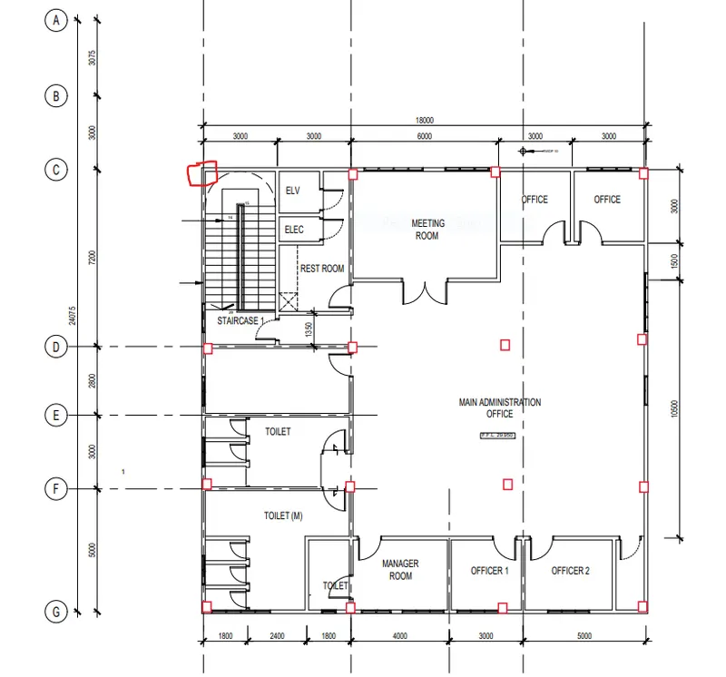
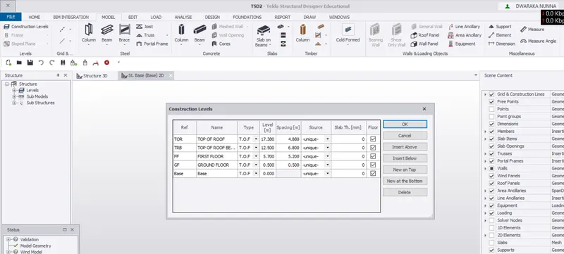
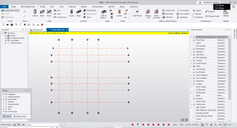
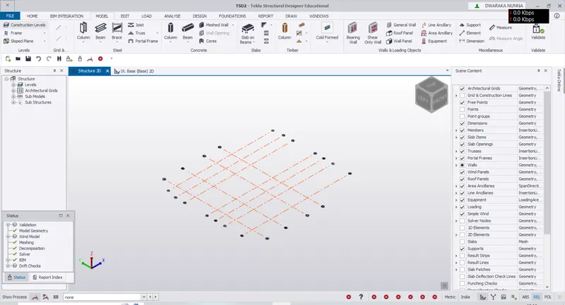
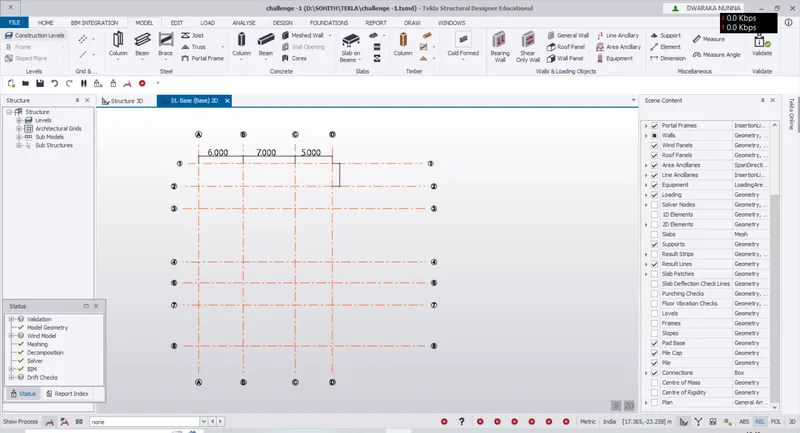
4. Model grid lines and construction levels as per Attachment 1. 1.1 and 1.2. All dimensions are in mm
The base level to be 500mm below ground level.
- OPEN the tsd software create new model.
- then go ot the model tab selece the costruction levels option
- now create the levels as per the 1.1 and 1.2.