Drafting of various geometries using Chamfer, Fillet tool in AutoCad
AIM: To DRAFT THE VARIOUS GEOMETRIES USING CHAMFER, FILLET TOOLS IN AUTOCAD.
INTRODUCTION: AutoCAD consists of a number of drawing and modification tools. Among the modification tools are the Chamfer, Fillet, Offset, Object snap, Rotate, Copy, Move, Mirror, Trim, Extend and Join. here we use some extra commands which are rectangle,circle polyline etc.
Chamfer: A bevel or chamfer is-
- an angled line that meets the end-points of two straight 2D points.
- a sloped transition between two surfaces or adjacent faces on a 3D solid.
The distances and angles that we specify are applied in the order taht we select the objects.
Fillet: A round or fillet is-
- an arc that is created as tangent between two 2D objects.
- a curved transition between two surfaces or adjacent faces on a 3D solid.
Offset: It is used to create concentric circles, parallel lines and parallel curves.
Object Snap: Object snap provide a way specify precise locations, such as endpoint, mid-point etc., on objects whenever we are prompted for a point within a command.We can offset an object at a specified distance or through a point.
Rotate: This tool rotates object around a base point. An object can be rotated either by entering the angle of rotation, or drag the object around its base point and specifying a point location to which we want to rotate the object to. We can also enter c to create a copy of the selected objects, or enter r to rotate the selected objects from a specified reference angle to an absolute angle.
Copy: This command copies objects at a specified distance in a specified direction. With the COPYMODE system variable, we can control whether multiple copies are to be created automatically.
Move: It moves objects a specified distance in a specified direction. We can use coordinates, grid snaps, object snaps, and other tools to move objects with precision.
Mirror: This command is used to create a mirrored copy of selected objects. Using this command we can create objects that represent half of a drawing, select them, and mirror them across a specified line to create the other half.
Trim: It trims objects to meet the edges of other objects. There are two modes that can be used to trim objects, viz. Quick mode and Standard mode.
Extend: This command extends objects to meet the edges of other objects. To extend objects, we first need to select the boundaries, and then press Enter and select the objects that we want to extend. To use all objects as boundaries, we press Enter at the first Select Objects prompt.
Join: It joins the endpoints of linear and curved objects to create a single object. A series of finite linear and open curved objects at their common endpoints are combined to create a single 2D or 3D object. The resulting object depends on the types of objects selected, the type of object selected first, and whether the objects are coplanar.
PROCEDURE :
1A.
1.open the auto cad software & create a template file in the folder.
2.prepare the drawing sheet as comfotable as like you by setting up & start up.
3.enter the line command in the command bar L or polyline PL . specify the first point where can do start the drawing,move the coursor in the direction to the next point ,then give the distance of the line that will be a next point. like that draw the footing inthe shape as per the given diagram based on the measurements.
4.draw the circles with given radius in the geometrie,by using circle command.
5.use erase command to remove any junk lines in the diagram.
6.use the dimension (DIMLINEAR) tool to view the specified distance of the object.
7.for copying the objects use copy command CO in the command bar.
8.to move the objects use move command M in the command bar.
9.use Mtext command (T) to create the text any where on the work sace.
10.save the completed the drawing by ctrl + s.
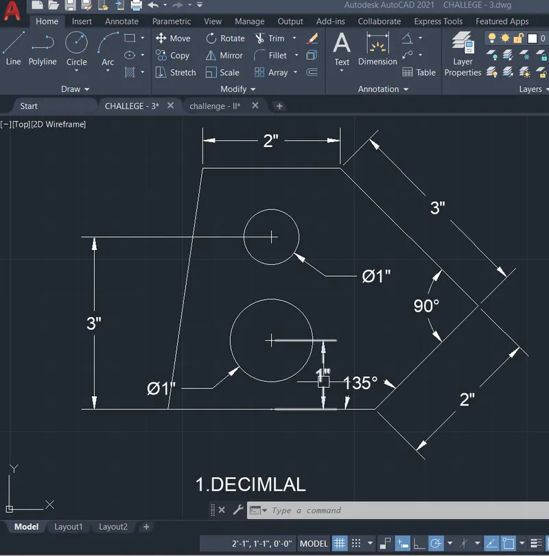
2A.
1.open the auto cad software & create a template file in the folder.
2.prepare the drawing sheet as comfotable as like you by setting up & start up.
3.enter the line command in the command bar L or polyline PL . specify the first point where can do start the drawing,move the coursor in the direction to the next point ,then give the distance of the line that will be a next point. like that draw the footing inthe shape as per the given diagram based on the measurements.
4.use erase command to remove any junk lines in the diagram.
5.use the dimension (DIMLINEAR) tool to view the specified distance of the object.
6.for copying the objects use copy command CO in the command bar.
7.to move the objects use move command M in the command bar.
8.use Mtext command (T) to create the text any where on the work sace.
9.save the completed the drawing by ctrl + s.
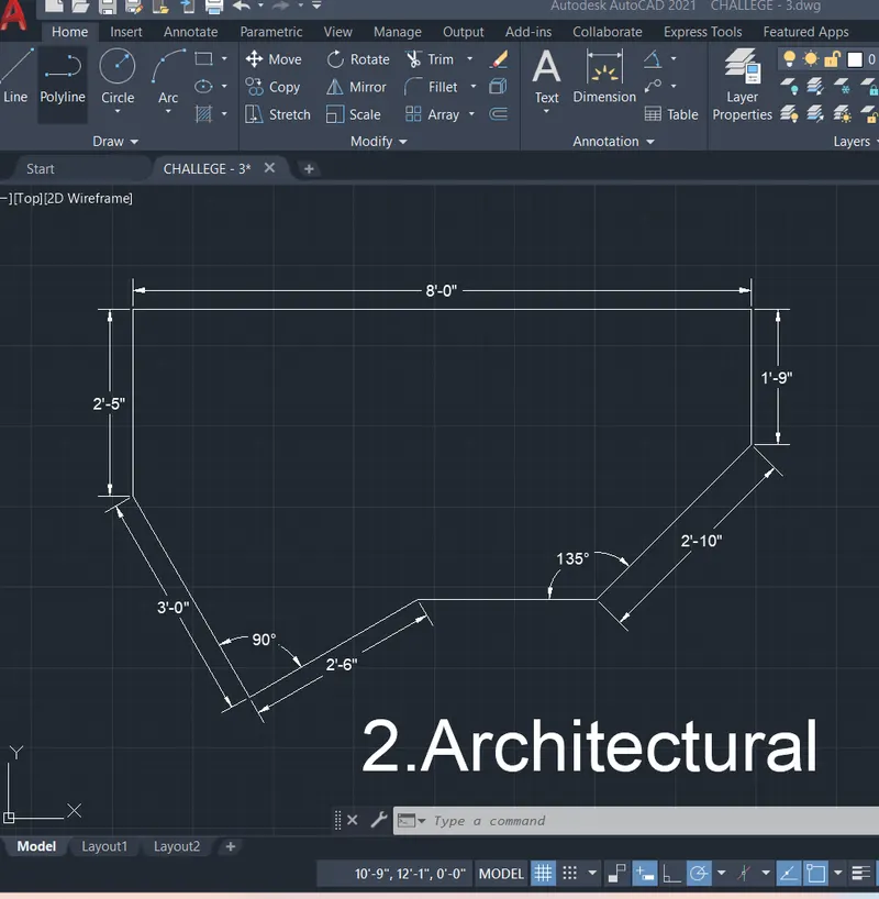
3A.
1.open the auto cad software & create a template file in the folder.
2.prepare the drawing sheet as comfotable as like you by setting up & start up.
3.enter the line command in the command bar L or polyline PL . specify the first point where can do start the drawing,move the coursor in the direction to the next point ,then give the distance of the line that will be a next point. like that draw the footing inthe shape as per the given diagram based on the measurements.
4.draw the circle with given radius in the geometrie,by using circle command.
5.use erase command to remove any junk lines in the diagram.
6.use the dimension (DIMLINEAR) tool to view the specified distance of the object.
7.for copying the objects use copy command CO in the command bar.
8.to move the objects use move command M in the command bar.
9.use Mtext command (T) to create the text any where on the work sace.
10.save the completed the drawing by ctrl + s.
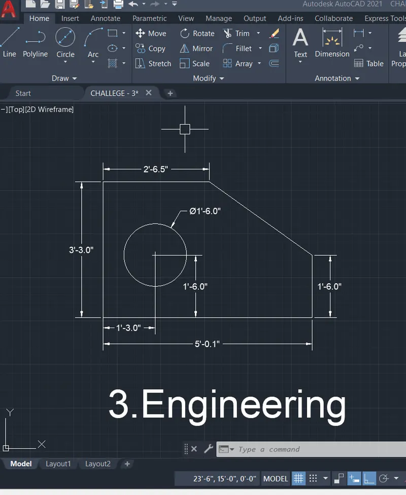
4A.
1.open the auto cad software & create a template file in the folder.
2.prepare the drawing sheet as comfotable as like you by setting up & start up.
3.enter the line command in the command bar L or polyline PL . specify the first point where can do start the drawing,move the coursor in the direction to the next point ,then give the distance of the line that will be a next point. like that draw the footing inthe shape as per the given diagram based on the measurements.
4.use erase command to remove any junk lines in the diagram.
5.use extend command to connect the line with edges.
6.use the dimension (DIMLINEAR) tool to view the specified distance of the object.
7.for copying the objects use copy command CO in the command bar.
8.to move the objects use move command M in the command bar.
9.use Mtext command (T) to create the text any where on the work sace.
10.save the completed the drawing by ctrl + s.
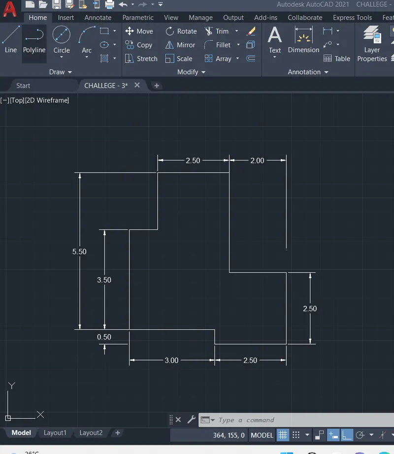
5A.
1.open the auto cad software & create a template file in the folder.
2.prepare the drawing sheet as comfotable as like you by setting up & start up.
3.enter the line command in the command bar L or polyline PL . specify the first point where can do start the drawing,move the coursor in the direction to the next point ,then give the distance of the line that will be a next point. like that draw the footing inthe shape as per the given diagram based on the measurements.
4.draw the circle with given radius in the geometrie,by using circle command.
5.use erase command to remove any junk lines in the diagram.
6.use the dimension (DIMLINEAR) tool to view the specified distance of the object.
7.for copying the objects use copy command CO in the command bar.
8.to move the objects use move command M in the command bar.
9.use Mtext command (T) to create the text any where on the work sace.
10.save the completed the drawing by ctrl + s.
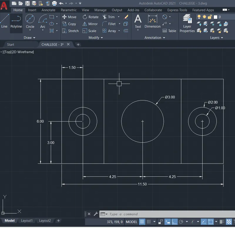
6A.
1.open the auto cad software & create a template file in the folder.
2.prepare the drawing sheet as comfotable as like you by setting up & start up.
3.enter the line command in the command bar L or polyline PL . specify the first point where can do start the drawing,move the coursor in the direction to the next point ,then give the distance of the line that will be a next point. like that draw the footing inthe shape as per the given diagram based on the measurements.
4.use erase command to remove any junk lines in the diagram.
5.use the dimension (DIMLINEAR) tool to view the specified distance of the object.
6.for copying the objects use copy command CO in the command bar.
7.to move the objects use move command M in the command bar.
8.use Mtext command (T) to create the text any where on the work sace.
9.save the completed the drawing by ctrl + s.
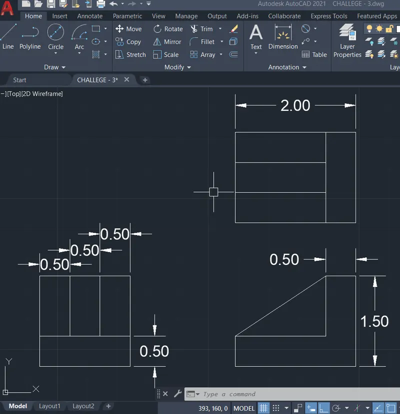
7A.
1.open the auto cad software & create a template file in the folder.
2.prepare the drawing sheet as comfotable as like you by setting up & start up.
3.enter the line command in the command bar L or polyline PL . specify the first point where can do start the drawing,move the coursor in the direction to the next point ,then give the distance of the line that will be a next point. like that draw the footing inthe shape as per the given diagram based on the measurements.
4.draw the circle with given radius in the geometrie,by using circle command.
5.draw the rectangle by using rectangle command with the given dimensions.
6.shape the edges with an specified radius of arc by using fillet command.
7.use erase command to remove any junk lines in the diagram & trim the extra lines by using trim command.
8.use the dimension (DIMLINEAR) tool to view the specified distance of the object.
9.for copying the objects use copy command CO in the command bar.
10.to move the objects use move command M in the command bar.
11.use Mtext command (T) to create the text any where on the work sace.
12.save the completed the drawing by ctrl + s.
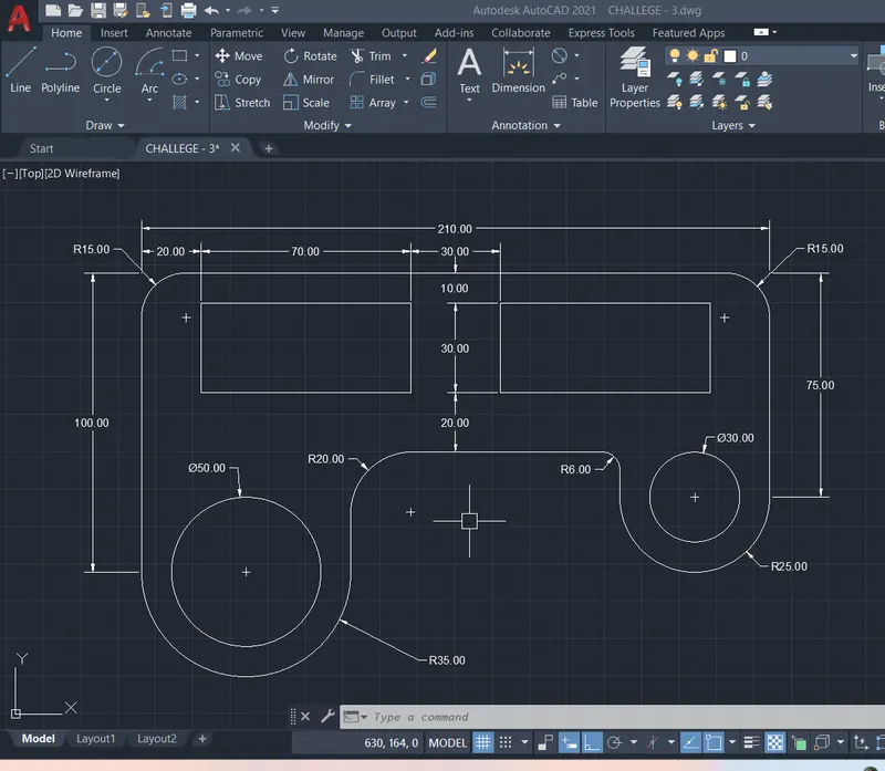
8A.
1.open the auto cad software & create a template file in the folder.
2.prepare the drawing sheet as comfotable as like you by setting up & start up.
3.draw the circles with given radius in the geometrie,by using circle command.
4.draw the arc by using arc command of start , end,radius. join the both circles with a tangent by line command.
5.use mirror command to mirroring the image.
5.use erase command to remove any junk lines in the diagram & trim the extra lines by using trim command.
6.use the dimension (DIMLINEAR) tool to view the specified distance of the object.
7.for copying the objects use copy command CO in the command bar.
8.to move the objects use move command M in the command bar.
9.use Mtext command (T) to create the text any where on the work sace.
10.save the completed the drawing by ctrl + s.
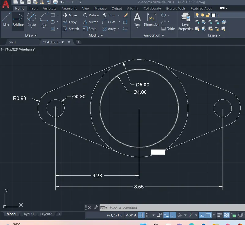
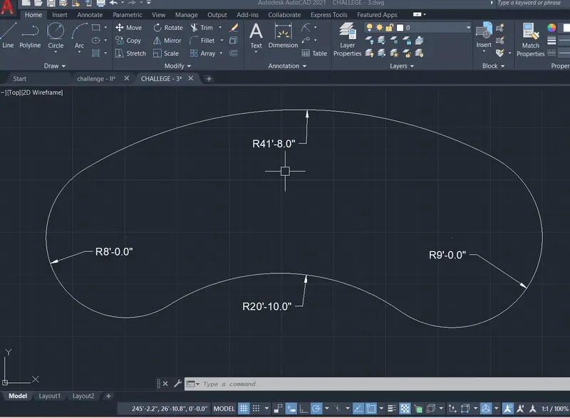
9A.
1.open the auto cad software & create a template file in the folder.
2.prepare the drawing sheet as comfotable as like you by setting up & start up.
3.draw the two circles with given radius in the geometrie,by using circle command.
4.similarly,draw the circle by connecting bothe the circles,by using circle command of tan,tan,radius .
5.use erase command to remove any junk lines in the diagram & trim the extra lines by using trim command.
6.use the dimension (DIMLINEAR) tool to view the specified distance of the object.
7.for copying the objects use copy command CO in the command bar.
8.to move the objects use move command M in the command bar.
9.use Mtext command (T) to create the text any where on the work sace.
10.save the completed the drawing by ctrl + s.
10A.
1.open the auto cad software & create a template file in the folder.
2.prepare the drawing sheet as comfotable as like you by setting up & start up.
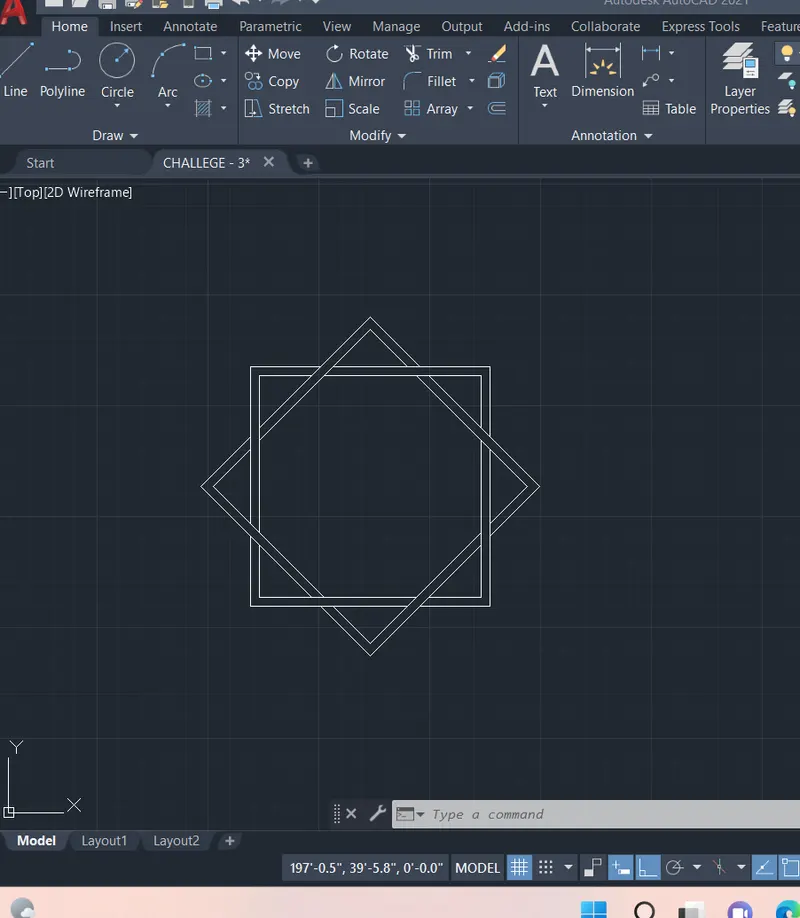
3.enter the line command in the command bar L or polyline PL . specify the first point where can do start the drawing,move the coursor in the direction to the next point ,then give the distance of the line that will be a next point. like that draw the footing inthe shape as per the given diagram based on the measurements.
4.use rectangle command to drwa a square.
5.use erase command to remove any junk lines in the diagram & trim the extra lines by using trim command.
6.for copying the objects use copy command CO in the command bar.
7.to move the objects use move command M in the command bar.
8.to rotate the objects use rotate commande.
9.save the completed the drawing by ctrl + s.
11A.
1.open the auto cad software & create a template file in the folder.
2.prepare the drawing sheet as comfotable as like you by setting up & start up.
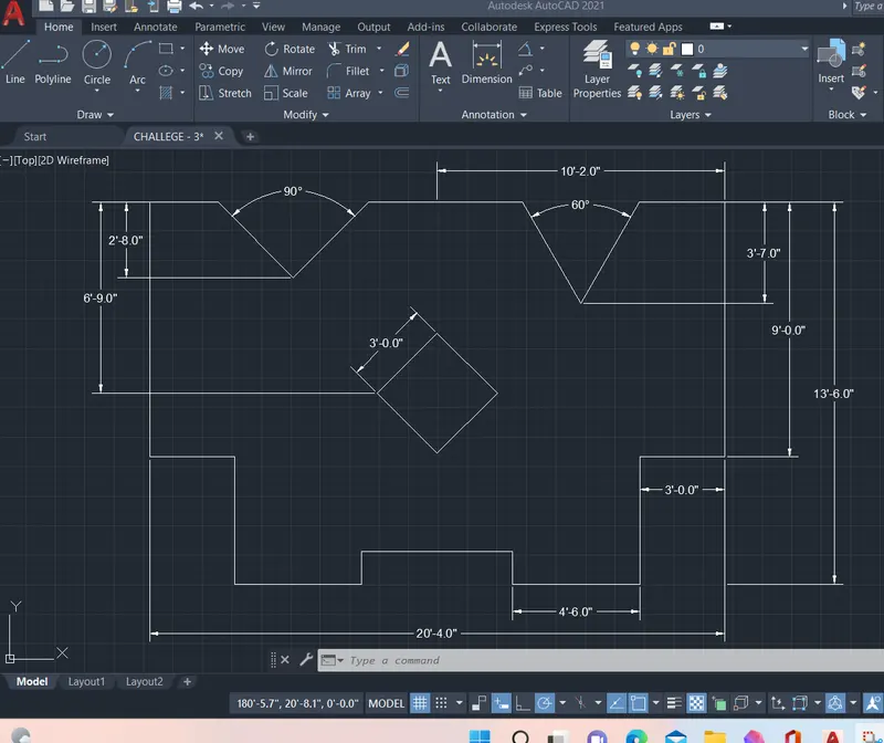
3.enter the line command in the command bar L or polyline PL . specify the first point where can do start the drawing,move the coursor in the direction to the next point ,then give the distance of the line that will be a next point. like that draw the footing inthe shape as per the given diagram based on the measurements.
4.use rectangle command to drwa a square as per given dimensions.
5.use mirror command to mirroring the image.
6.use erase command to remove any junk lines in the diagram & trim the extra lines by using trim command.
7.use the dimension (DIMLINEAR) tool to view the specified distance of the object.
8.for copying the objects use copy command CO in the command bar.
9.to move the objects use move command M in the command bar.
10.use Mtext command (T) to create the text any where on the work sace.
11.save the completed the drawing by ctrl + s.
RESULTS :
- THE VARIOUS GEOMETRIES ARE DRAWN USING CHAMFER, FILLET ,& SOME TOOLS IN AUTOCAD.
- Drawn figures 1 - 11 are uploded in the above, like a picture.