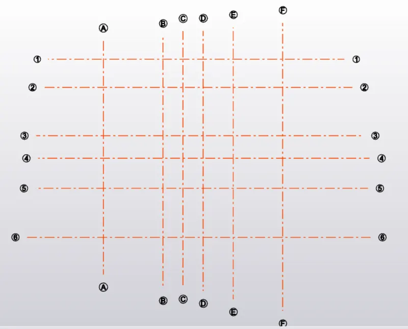
To plan a structural layout and to create grids using TSD
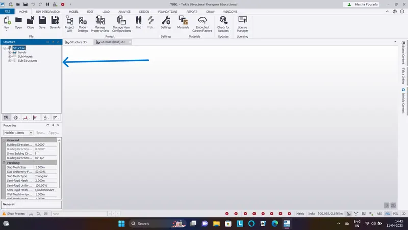
1.1)Project Work Space is the space present in the Tekla Structural Designer software,where it contains all the data of the project in different aspects such as Structure,Groups,Loading,Wind,Status,Connections.
The Project Work Space is present on the top left corner of the screen as marked below.
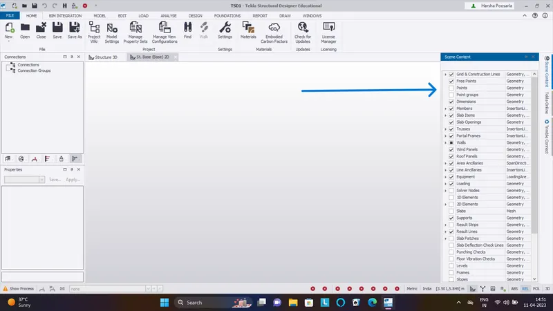
1.2)Scene Content is the tab shown below as marked and it is present on the top right corner of the screen.
It is the tab,where we can mark the required things such as to be visible on the screen and the unmarked things in this tab are not visible on the screen.
1.3)For us to view different scene views,we must have different levels.So,initially,we have to create different levels.
We go to Model Tab>Construction Levels.
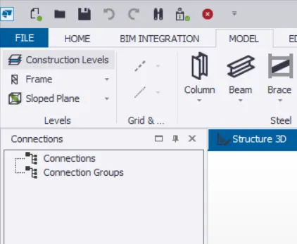
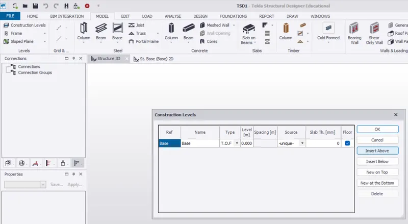
We insert the levels above the base as shown.
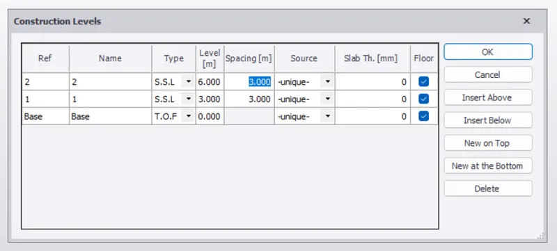
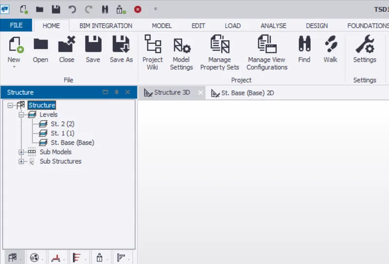
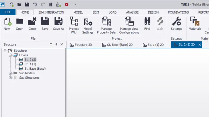
Then,in the Project Work Space>Structure>Levels,we select the required levels and we can view them.
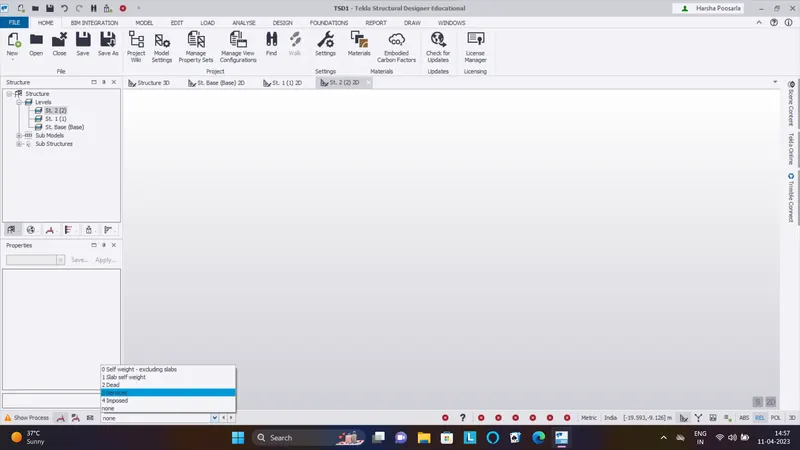
1.4)The Loading List is available on the bottom left of the screen.
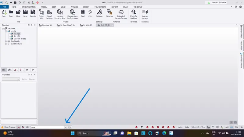
On clicking it,we can see the different types of the loads available.
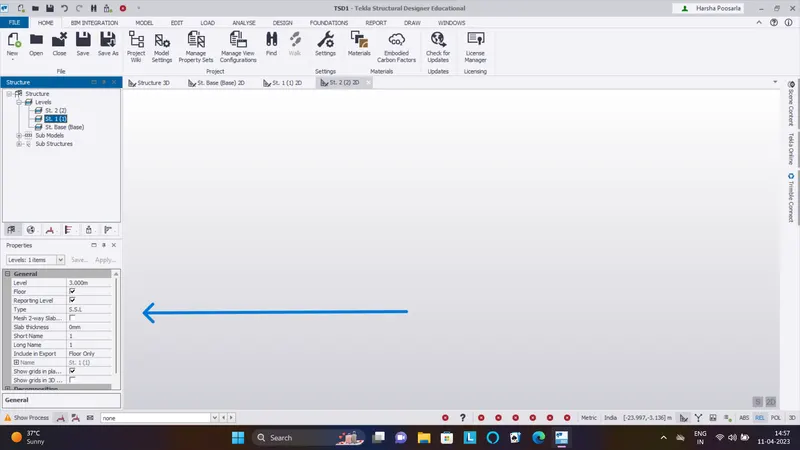
1.5)The Properties Window is available on the bottom left under the Project Work Space.
This tab contains all the properties of the selected member in the project.
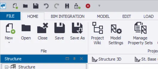
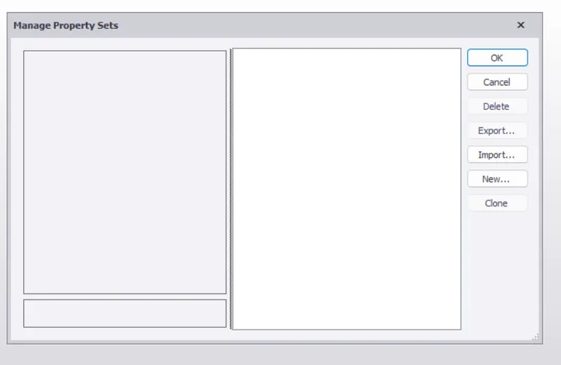
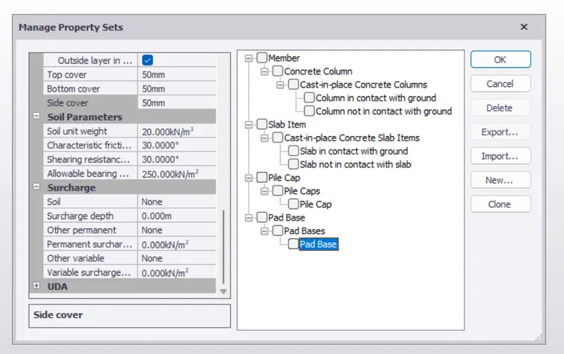
2.1)For us to add the cover properties to the members,we go to Home Tab>Manage Property Sets.
We add the new members as per the requirement,by clicking on New...
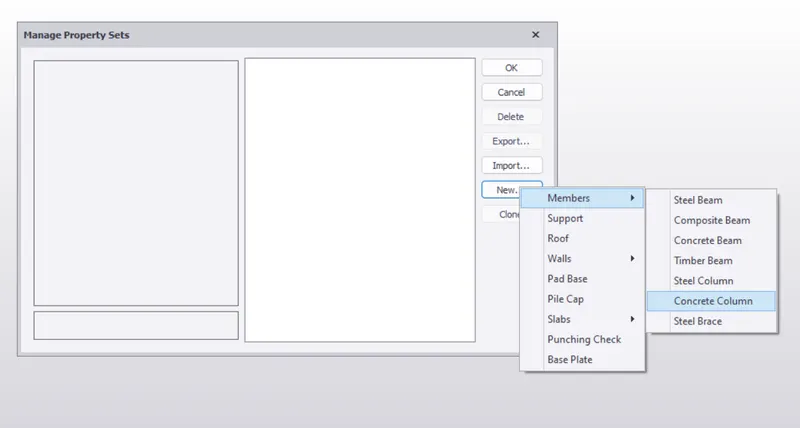
Then,New...>Members>Concrete Column.
Where then a concrete column gets added up in the file.And in the similar manner,we add one more too.
And we rename them as Column in contact with ground and Column not in contact with ground respectively.
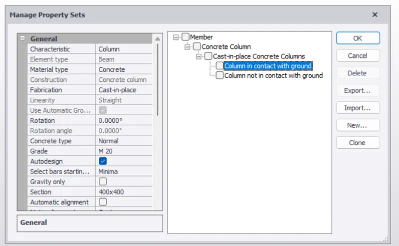
Where we then change the value of the cover for the columns.
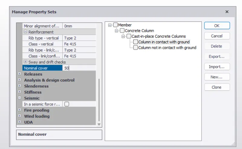
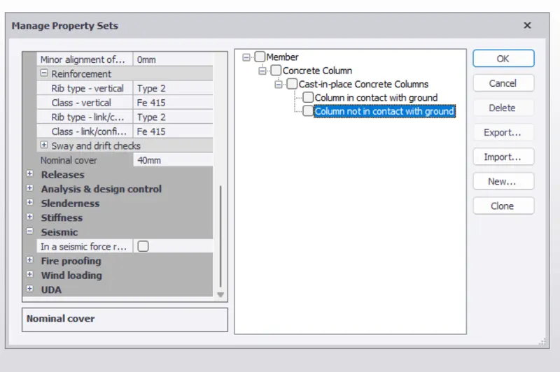
2.2)In the similar manner,we add the Slab member too and change their respective cover values.
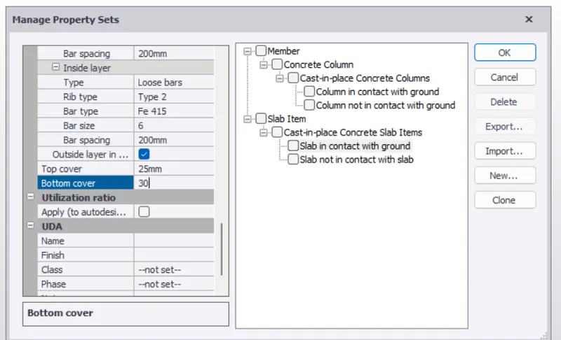
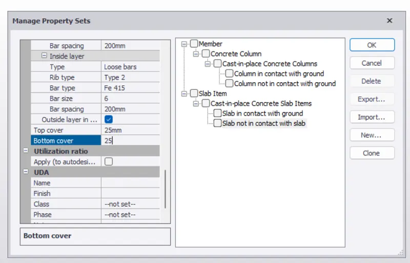
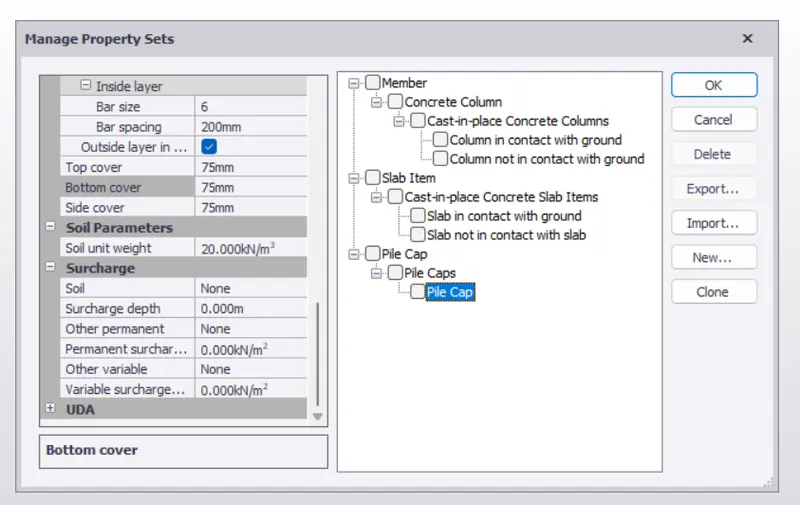
2.3)And we even create a Pile Cap and change its cover value too.
2.4)And lastly,we add a Pad Base and and change its cover to 50 mm.
3)Basing upon the drawings provided,the grid lines present in the drawings are just for knowing the distance between the specific points as shown but not for mentioning the column positioning at their intersections.
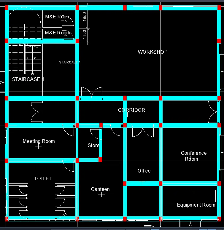
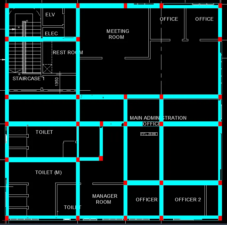
So,basing upon the plans provided,the below are column and beam layout for the Ground Floor and First Floor respectively.
So,here the columns are positioned in such a way that they don't interfere any passage way and are only placed in the walls only.
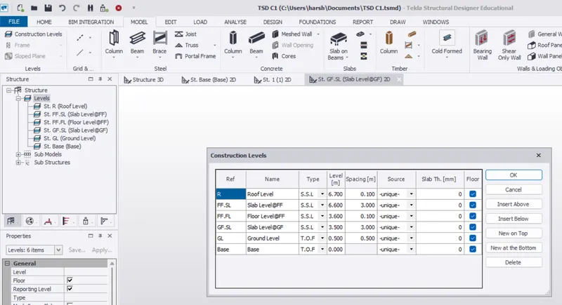
4)The required Construction Lines are created by going to Model Tab>Construction Levels.
Where the required construction levels are formed as shown basing upon the plans provided.
The Grid Lines are also formed in the same manner,as going to Model Tab>Grid Lines.
Where the required grid lines are formed basing upon the column layut formed.