Creating a Floor plan, Footing detail and Isometric view using AutoCad
Aim:To draw the given various diagrams in AutoCAD using any coordinate system and by using various commands,functions,etc., present in the AutoCAD.
Process:Here,we use any one of the Coordinate Sytems available to draw the diagrams in AutoCAD.And we even use various functions present in AutoCAD such as COPY,etc.
C 1
Aim:
To draw the given image using AutoCAD using any of the Coordinate System aswell as the functions available in AutoCAD.
Process:
For drawing this image we use the Relative Rectangular Coordinate System.And we seggregate the image into various parts to make the drawing process easier.And here,we even use the Object Snap to the reference of the points easily.
We use the LINE Command either just by entering LINE in COMMAND BAR or by selecting the option on the Ribbon Bar or on Tool Palette or simply by L+ENTER.
We can even close the Figure by using CLOSE in COMMAND BAR or entering a suitable point.
FIRST BASE
We use the Line Command.
- Specify the first point:0,0.50
- Specify the next point:@0.90,0
- Specify the next point:@0,0.25
- Specify the next point:@-0.90,0
We Close the Line.
SECOND BASE
We use the Line Command.
- Specify the first point:Using the OBJECT SNAP,we select the mid point of the top line of First Base from where we start the drawing where this mid point acts as a reference point.
- Specify the next point:@-0.25,0
- Specify the next point:@0,0.40
- Specify the next point:@0.50,0
- Specify the next point:@0,-0.40
THIRD BASE
We use the Line Command.
- Specify the first point:Using the OBJECT SNAP,we select the mid point of the top line of the Second Base from where we start the drawing where this mid point acts as a reference point.
- Specify the next point:@-0.20,0
- Specify the next point:@0,0.40
- Specify the next point:@0.40,0
- Specify the next point:@0,-0.40
WALL
We use the Line Command.
- Specify the first point:Using the OBJECT SNAP,we select the mid point of the top line of the Third Base from where we start the drawing where this mid point acts as a reference point.
- Specify the next point:@-0.15,0
- Specify the next point:@0,0.60
- Specify the next point:@0.30,0
- Specify the next point:@0,-0.60
We use the Line Command.
- Specify the first point:Using the OBJECT SNAP,we select the suitable point on the left top from the previous drawing,from where we proceed with the drawing.
- Specify the next point:@0,0.05
- Specify the next point:@0.30,0
- Specify the next point:@0,-0.05
We use the Line Command.
- Specify the first point:Using the OBJECT SNAP,we select the suitable point on the left top from the previous drawing,from where we proceed with the drawing.
- Specify the next point:@0,1
- Specify the next point:@0.30,0
- Specify the next point:@0,-1
BLOCK behind STEPS
We use the Line Command.
- Specify the first point:Using the OBJECT SNAP,we select the suitable point on the right top of the wall of first section,from where we proceed the drawing.
- Specify the next point:@1.15,0
- Specify the next point:@0,-0.60
- Specify the next point:@-1.15,0
STEPS
We use the Line Command.
- Specify the first point:Using the OBJECT SNAP,we select the suitable point on the top left of the Third Base,from where we proceed the drawing.
- Specify the next point:@-1.15,0
- Sepcify the next point:@0,-0.15
- Specify the next point:@1.15,0
We use the Line Command.
- Specify the first point:Using the OBJECT SNAP,we select the suitable point on the top left of the previous drawing,from where we proceed with the drawing.
- Specify the next point:@0.30,0
- Specify the next point:@0,0.15
- Specify the next point:@0.30,0
- Specify the next point:@0,0.15
- Specify the next point:@0.30,0
- Specify the next point:@0,0.15
- Specify the next point:@0.30,0
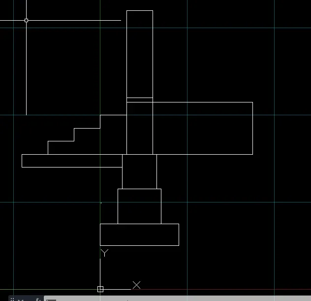
Result:
Thus,the given diagram is drawn in AutoCAD.
C 2
Aim:
To draw the given image using AutoCAD using any of the Coordinate System aswell as the functions available in AutoCAD.
Process:
For drawing this image we use the Relative Rectangular Coordinate System.And we seggregate the image into various parts to make the drawing process easier.And here,we even use the Object Snap to the reference of the points easily.
We use the LINE Command either just by entering LINE in COMMAND BAR or by selecting the option on the Ribbon Bar or on Tool Palette or simply by L+ENTER.
We can even close the Figure by using CLOSE in COMMAND BAR or entering a suitable point.
OUTER PART
We use the Line Command.
- Specify the first point:1,1
- Specify the next point:@1,0
- Specify the next point:@0,0.15
- Specify the next point:@-0.38,0.25
- Specify the next point:@0,1.60
- Specify the next point:@-0.24,0
- Specify the next point:@0,-1.60
- Specify the next point:@-0.38,-0.25
We Close the Line.
VERTICAL BARS
We use the Line Command.
- Specify the first point:Using the OBJECT SNAP,we select the suitable point on the left top of the Outer Part from where we proceed with the drawing.
- Specify the next point:@0.04,0
- Specify the next point:@0,-1.96
- Specify the next point:@-0.38,0
- Specify the next point:@0,0.05
We use the Line Command.
- Specify the first point:Using the OBJECT SNAP,we select the suitable point on the right top of the Outer Part from where we proceed with the drawing.
- Specify the next point:@-0.04,0
- Specify the next point:@0,-1.96
- Specify the next point:@0.38,0
- Specify the next point:@0,0.05
HORIZONTAL BARS
We use the Line Command.
- Specify the first point:Using the OBJECT SNAP,we select the suitable point on the top of the right vertical reinforcement from where we proceed with the drawing.
- Specify the next point:@0,-0.20
- Specify the next point:@0.16,0
Now,the horizontal bar is formed,where we copy this several times to form the entire horizontal reinforcement.
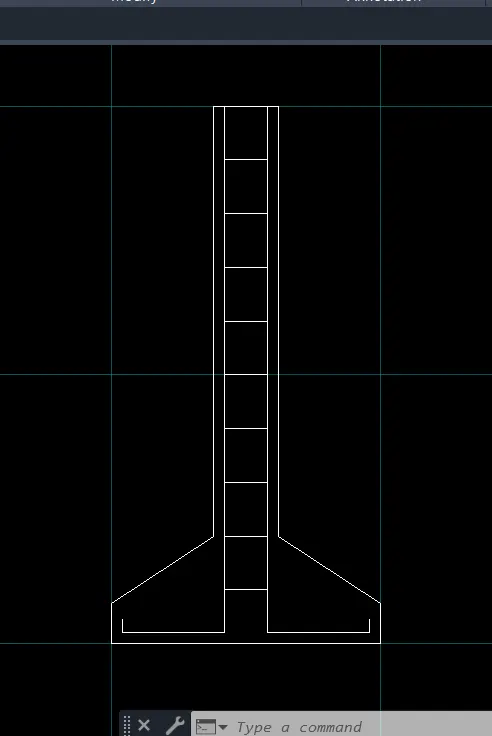
Result:
Thus,the given diagram is drawn in AutoCAD.
C 3
Aim:
To draw the given image using AutoCAD using any of the Coordinate System aswell as the functions available in AutoCAD.
Process:
For drawing this image we use the Relative Rectangular Coordinate System.And we seggregate the image into various parts to make the drawing process easier.And here,we even use the Object Snap to the reference of the points easily.
We use the LINE Command either just by entering LINE in COMMAND BAR or by selecting the option on the Ribbon Bar or on Tool Palette or simply by L+ENTER.
We can even close the Figure by using CLOSE in COMMAND BAR or entering a suitable point.
We use the Line Command.
- Specify the first point:1,1
For this diagram,rather than using much commands,drawing using the Polar Mode and using the Dynamic Mode and Object Snap we can draw faster just basing upon the dimensions given.
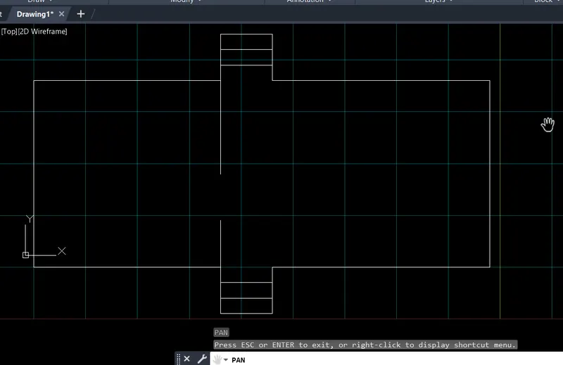
Result:
Thus,the given diagram is drawn in AutoCAD.
C 4
Aim:
To draw the given image using AutoCAD using any of the Coordinate System aswell as the functions available in AutoCAD.
Process:
For drawing this image we use the Relative Rectangular Coordinate System.And we seggregate the image into various parts to make the drawing process easier.And here,we even use the Object Snap to the reference of the points easily.
We use the LINE Command either just by entering LINE in COMMAND BAR or by selecting the option on the Ribbon Bar or on Tool Palette or simply by L+ENTER.
We can even close the Figure by using CLOSE in COMMAND BAR or entering a suitable point.
BASE
We use the Line Command.
- Specify the first point:1,0
- Specify the next point:@0.90,0
- Specify the next point:@0,0.45
- Specify the next point:@-0.90,0
We Close the Line.
FOOTINGS over BASE
We use the Line Command.
- Specify the first point:Using the OBJECT SNAP,we select the suitable point on the left top of the Base,from where we proceed with the drawing.
- Specify the next point:@0.15,0
- Specify the next point:@0,0.40
- Specify the next point:@0.05,0
- Specify the next point:@0,0.30
- Specify the next point:@0.05,0
- Specify the next point:@0,0.60
- Specify the next point:@0.40,0
- Specify the next point:@0,-0.60
- Specify the next point:@0.05,0
- Specify the next point:@0,-0.30
- Specify the next point:@0.05,0
- Specify the next point:@0,-0.40
WALL
- Specify the first point:Using the OBJECT SNAP,we select the suitable point on the left top of the Footings,from where we proceed with the diagram.
- Specify the next point:@0.05,0
- Specify the next point:@0,1
- Specify the next point:@0.30,0
- Specify the next point:@0,-1
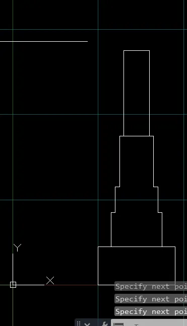
Result:
Thus,the given diagram is drawn in AutoCAD.
C 5
Aim:
To draw the given image using AutoCAD using any of the ISO PLANE MODEs aswell as the functions available in AutoCAD.
Process:
We seggregate the image into various parts to make the drawing process easier.And here,we even use the Object Snap to the reference of the points easily.
We use the LINE Command either just by entering LINE in COMMAND BAR or by selecting the option on the Ribbon Bar or on Tool Palette or simply by L+ENTER.
We can even close the Figure by using CLOSE in COMMAND BAR or entering a suitable point.
We even,use ISOPLANE LEFT and ISOPLANE RIGHT Alignments to draw the images.
In these diagrams,most of the things are made using the POLAR MODE,where we enter the dimensions on the screen using Dynamic Mode where we align the lines on the Isoplane.
We use the Line Command.
- Specify the first point:1,1
Where,we use the ISOPLANE RIGHT Mode,where we can draw the vertical lines as well as the right side lines,basing upon the given dimensions we form the lines.
And,then we go to the ISOPLANE LEFT Mode,where we draw the remaining lines as per the given diagram.
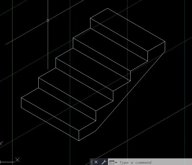
Result:
Thus,the given diagram is drawn in AutoCAD.
C 6
Aim:
To draw the given image using AutoCAD using any of the ISO PLANE MODEs aswell as the functions available in AutoCAD.
Process:
We seggregate the image into various parts to make the drawing process easier.And here,we even use the Object Snap to the reference of the points easily.
We use the LINE Command either just by entering LINE in COMMAND BAR or by selecting the option on the Ribbon Bar or on Tool Palette or simply by L+ENTER.
We can even close the Figure by using CLOSE in COMMAND BAR or entering a suitable point.
We even,use ISOPLANE LEFT and ISOPLANE RIGHT Alignments to draw the images.
In these diagrams,most of the things are made using the POLAR MODE,where we enter the dimensions on the screen using Dynamic Mode where we align the lines on the Isoplane.
We use the Line Command.
- Specify the first point:1,1
Where,we use the ISOPLANE RIGHT Mode,where we can draw the vertical lines as well as the right side lines,basing upon the given dimensions we form the lines.
And,then we go to the ISOPLANE LEFT Mode,where we draw the remaining lines as per the given diagram.For this diagram,while drawing the upper triangular part,we have a draw a reference line at bottom at door,where we draw a vertical line from it's centre to the given height where we join thereafter forming the upper triangular part.
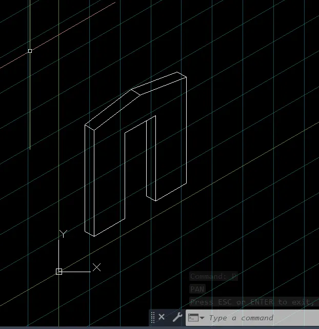
Result:
Thus,the given diagram is drawn in AutoCAD.
Result:Hence,all the given diagrams are drawn in the Auto CAD Software.