Drafting of various geometries using Chamfer, Fillet tool in AutoCad
Aim:To draw the given figures in AutoCAD using various functions and Commands.
Process:To draw the given diagrams we use various Functions and Commands and we draw a few reference lines to get the ultimate diagram where we erase the reference lines thereafter.
Figure 1
Aim:
To draw the given diagram in AutoCAD.
Process:
After setting up the page in DECIMAL Units and as per the requirements,we proceed on with drawing the diagram.
- Initially,we draw the base line of 3.00 units after selecting the proper starting point using the LINE Command.
- Then,we draw the next line of 2.12 units at an angle of 135 degrees with respect to the previous line using the POLAR MODE and we continue further with drawing the next line of 2.83 units at an angle of 90 degrees with respect to the previous line.
- At last we draw the top line of 2.00 units where we Close the diagram thereafter.
- Now,to draw the circle present inside,we draw 2 horizontal lines at a height of 1.00 units and 2.50 units from the bottom respectively.
- And we even draw a vertical line bisecting the bottom and top line which gives the idea of the centres of both the circles.
- After this,we draw the circles basing upon the given diameters.
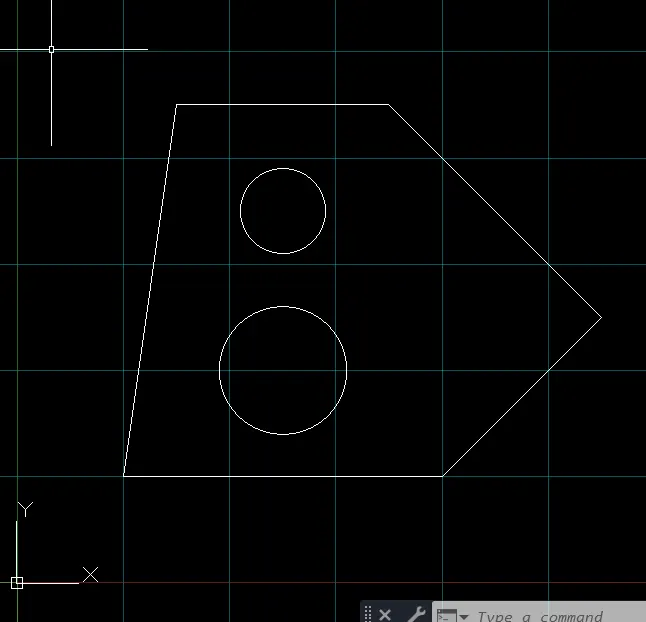
Result:
Hence,the given diagram is formed in AutoCAD.
Figure 2
Aim:
To draw the given diagram in AutoCAD.
Process:
After setting up the page in ARCHITECTURAL Units and as per the requirements,we proceed on with drawing the diagram.
- Initially,we draw the top line of 8" after selecting the proper starting point using the LINE Command.
- Now,we draw the both the side lines as per the given lengths using the ORTHO MODE.
- Now,we proceed by drawing the slanting line present on the right of the length of 2'-10" at and angle of 225 degrees with respect to the previous line along clock-wise direction.
- We don't know the length of the bottom horizontal line,where we just draw a horizontal reference line of required length.
- Now,apart from the diagram,we draw the L shaped figure where the vertical line is of the length of 3' and the horizontal line is of length of 2'-6".
- After drawing this,we bring this to the left side vertical line and fix it at the tip of it.
- Where,now we use ROTATE Command to rotate it to till it touches the horizontal reference line.
- Now,we TRIM the extra line present as per the figure.
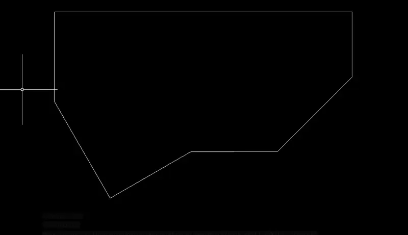
Result:
Hence,the given diagram is formed in AutoCAD.
Figure 3
Aim:
To draw the given diagram in AutoCAD.
Process:
After setting up the page in ENGINEERING Units and as per the requirements,we proceed on with drawing the diagram.
- After selecting a suitable starting point,intially,we draw the Outer Box using the RELATIVE RECTANGULAR COORDINATE SYSTEM using the LINE Command and even using POLAR MODE to draw the slanting line.
- Now,we draw a vertical reference line at a distance of 1'-3.0" from the left vertical line and we draw a horizontal reference line at a distance of 1'-6.0" from the base,where the centre of the circle can be formed.
- Now,from the formed centre,we draw the circle of diameter of 1'-6.0".
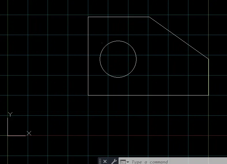
Result:
Hence,the given diagram is formed in AutoCAD.
Figure 4
Aim:
To draw the given diagram in AutoCAD.
Process:
After setting up the page in DECIMAL Units and as per the requirements,we proceed on with drawing the diagram.
- After selecting a suitable starting point,the figure can be drawn using the RELATIVE RECTANGULAR COORDINATE SYSTEM using the LINE Command basing upon the dimensions of the diagram.
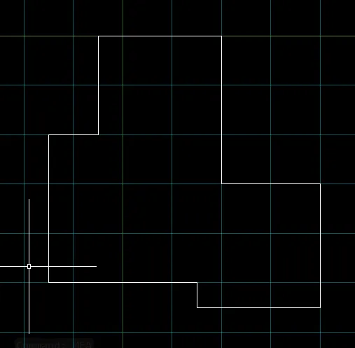
Result:
Hence,the given diagram is formed in AutoCAD.
Figure 5
Aim:
To draw the given diagram in AutoCAD.
Process:
After setting up the page in DECIMAL Units and as per the requirements,we proceed on with drawing the diagram.
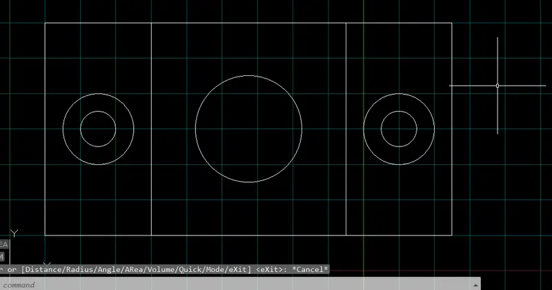
- After selecting a suitable starting point,the figure can be drawn using the RELATIVE RECTANGULAR COORDINATE SYSTEM using LINE Command basing upon the dimensions of the diagram,where the outer box can be drawn then.
- Now,the inner vertical lines are drawn,where the the distances of those are not given directly,but the distances of the centres of the circles is being mentioned,so on doubling it,we get the required distance.
- So,we draw the left vertical inner line at a distance of 3.00 units from the left vertical outer line.
- And,we draw the right vertical inner line at the same distance as that of the same as previous one.
- Now,references lines have to be made to draw the circles.
- A horizontal reference line is drawn at the centre i.e., at a distance of 3.00 units from the bottom,where this reference line will be usen for all the circles.
- A vertical reference line is to be made at a distance of 1.50 units from the left outer line and the same is to be drawn on the right side too.
- A vertical reference line is to be made at a distance of 2.75 units from the inner left or right line to form the centre for the middle circle.
- As,the centres of the all the circles ahve been formed,then,circles are drawn basing upon the given dimensions using CIRCLE Command.
- After which the reference lines are to be erased.
Result:
Hence,the given diagram is formed in AutoCAD.
Figure 6
Aim:
To draw the given diagram in AutoCAD.
Process:
After setting up the page in DECIMAL Units and as per the requirements,we proceed on with drawing the diagram.
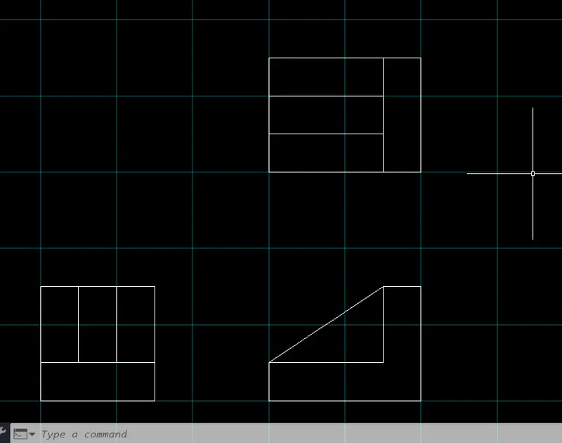
- This diagram is to be made as per the alignment of the figures.
- Initially,using the LINE Command the Outer Box can be formed,where we draw at first the left bottom figure.
- Then,the inner lines are to be drawn as per the dimensions.
- After which the bottom right figure can be drawn using the same process.
- Then,the top figure can be made using the same process.
Result:
Hence,the given diagram is formed in AutoCAD.
Figure 7
Aim:
To draw the given diagram in AutoCAD.
Process:
After setting up the page in DECIMAL Units and as per the requirements,we proceed on with drawing the diagram.
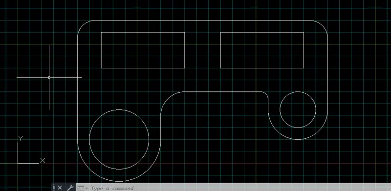
- This is a typical diagram,where many reference lines are to be usen and we even use the features such as FILLET,TRIM,etc.
- Initially,we start with drawing the upper line of length of 210 units.
- And,now,we draw the vertical on left side of 100 units and a vertical line of 75 units on the right side.
- Now,using the FILLET Command,we Fillet the edges on both the sides of radius of 15 units.
- Now,we draw the horizontal reference lines at a depth of 10 units and 40 units from the top respectively.
- As horizontal lines are present,drawing the vertical lines alone is sufficient to form the rectangles.
- Now,we draw the vertical lines in between the horizontal reference lines,a vertical line of 30 units are drawn at a distance of 20 units and 90 units respectively from the left and the same is repeated on the right side too to form the rectangle.
- And,one more horizontal reference line is drawn at a distance of 20 units from the rectangles.
- 2 more horizontal reference lines are to be made on both the sides to form the circles,so the mid points of those reference lines act as centres of the circles,where the 2 circles are formed on each side,where the outer is trimmed as per the requirement and then the vertical lines are drawn to fix with the upper horizontal reference line and the edges are filleted as per the given radius.
- Finally,the reference lines are trimmed to form the good image.
Result:
Hence,the given diagram is formed in AutoCAD.
Figure 8
Aim:
To draw the given diagram in AutoCAD.
Process:
After setting up the page in DECIMAL Units and as per the requirements,we proceed on with drawing the diagram.
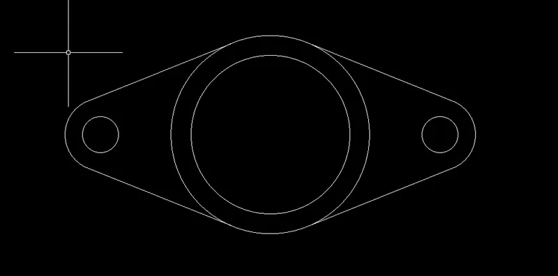
- This diagram starts with drawing the circles on all the 3 sides.
- Initially,a circle of diameter of 0.90 units is made where concentrically,a circle of radius of 0.90 units is to be made.
- Anonther set of circles is to be made on oppsite side where the distance to be maintained between the centres of the circles is 8.55 units.
- Now,exactly at the midpoint of these centres,2 concentric circles of diameters 4 and 5 units respectively are to be drawn.
- Now the tangents are to be drawn onouter cirlces on both sides to center outer circle.
- Now,the circles are to be trimmed as per the requirement.
Result:
Hence,the given diagram is formed in AutoCAD.
Figure 9
Aim:
To draw the given diagram in AutoCAD.
Process:
After setting up the page in ARCHITECTURAL Units and as per the requirements,we proceed on with drawing the diagram.
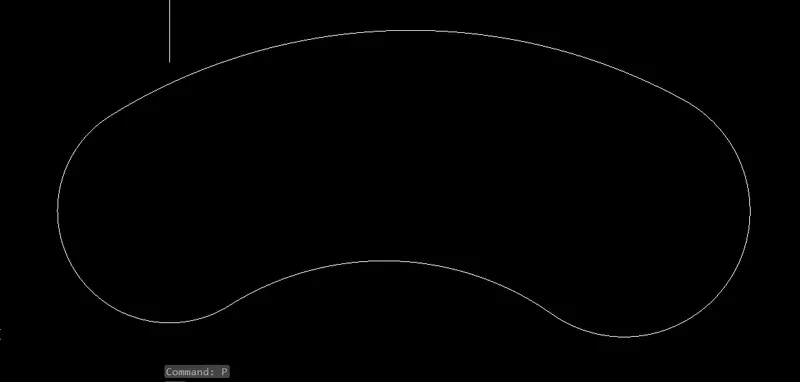
- Initially,2 circles of radii of 8' are to be drawn where the distance between those 2 centres should be 32'-6".
- Now,a bigger circle is to be drawn using CIRCLE Command i.e.,TAN TAN RADIUS Option,where we select 2 points on both the circles to form a circle as a tangent and the radius to be provided to this outer big circle is 41'-8".
- Now,similarily,a small inner cirlce to be formed similar to the above where the radius to be usen for this is 20'-10".
- Now,the 2 tangent circles along with the main circles are to be trimmed as per the image to get the exact figure.
Result:
Hence,the given diagram is formed in AutoCAD.
Figure 10
Aim:
To draw the given diagram in AutoCAD.
Process:
After setting up the page in DECIMAL Units and as per the requirements,we proceed on with drawing the diagram.
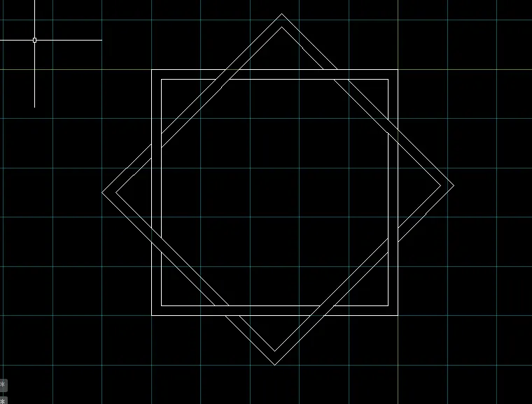
- This image seems to be a bit tricky but this actual easy one,where just TRIM and OFFSET Options are to be used.
- Initially,a square is formed,where forming the reference lines are to be drawn in both the directions,where then the rhombus of the same dimension is to be formed.
- Where,then we use the OFFSET Command to form the Square and Rhombus of lesser size parallel to previous ones.
- Now,we use the TRIM Command to trim the lines as per the Image.
Result:
Hence,the given diagram is formed in AutoCAD.
Figure 11
Aim:
To draw the given diagram in AutoCAD.
Process:
After setting up the page in ARCHITECTURAL Units and as per the requirements,we proceed on with drawing the diagram.
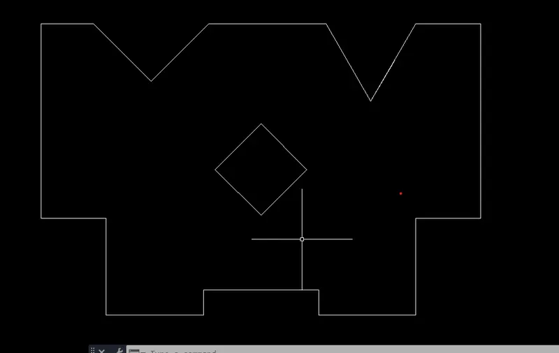
- Initally,the Outer Box is to be drawn using the LINE Command and using the RELATIVE RECTANGULAR COORDINATE SYSTEM.
- Now,2 horizontal reference lines are to be drawn at the depths of 2'-8" and 3'-7" from the top line.
- And a vertical reference line is to be exactly at the centre of the image.
- Basing upon these reference lines,i.e.,2 more new vertical reference lines are made at the centres of both the parts.
- Now,the coinciding points i.e.,coinciding points on the horizontal and vertical lines are usen for the drawing of angles as per the image.
- Now,the centre Rhombus is to be drawn after drawing a horizontal reference line at a depth of 6'-9" from the top.
- Where the Rhombus can be drawn as a square of side of 3' apart from the figure where this is rotated to a angle of 45 degrees and then using COPY Option,this can be transferred to the main figure using the Centre point as the Base point.
- Now,the reference lines are to be trimmed as per the image to form a good diagram.
Result:
Hence,the given diagram is formed in AutoCAD.
Result:Thus,the given diagrams are drawn In AutoCAD Software using various Commands and Options.