Creation of geometries by Coordinate system methods using AutoCad
Aim:To draw the given images using AutoCAD by providing the required commands by using the various Coordinate Systems.
Process:It just includes specifying the various points and by using the commands.We initially,start the diagram with LINE Command,this can be done by clicking on the LINE Diagram present on the Ribbon Bar,or by typing LINE in the Command Bar or just by L+ENTER.We can close the drawing of the image either by entering the the first point or just by C+ENTER.
Diagram 1(P 1)
Aim:
To the draw the given image by using all the coordinate systems.
Process:
We use the commands and specifying the various points by using all the various Coordinate Systems.
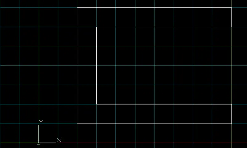
Absolute Coordinate System
Initially,we use the LINE Command thereafter by specifying the points.
- Specify the first point as (2,1).
- Specify the next point as (2,7).
- Specify the next point as (10,7).
- Specify the next point as (10,6).
- Specify the next point as (3,6).
- Specify the next point as (3,2).
- Specify the next point as (10,2).
- Specify the next point as (10,1).
- Specify the next point as (2,1) or by closing the drawing.
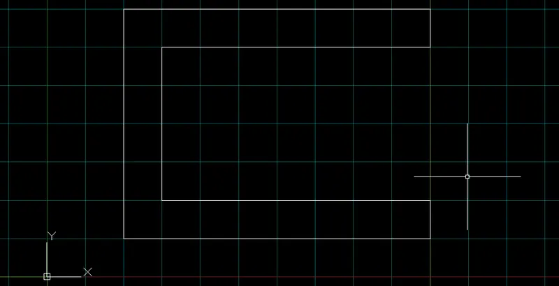
Relative Rectangular Coordinate System
Initially,we use the LINE Command therafter by specifying the points.
- Specify the first point as (2,1).
- Specify the next point as (@0,6).
- Specify the next point as (@8,0).
- Specify the next point as (@0,-1).
- Specify the next point as (@-7,0).
- Specify the next point as (@0,-4).
- Specify the next point as (@7,0).
- Specify the next point as (@0,-1).
- Specify the next point as (2,1) or by closing the drawing.
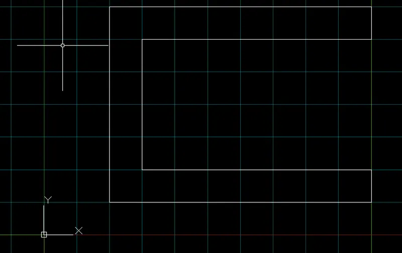
Relative Polar Coordinate System
Initially,we use the LINE Command therafter by specifying the points.
- Specify the first point as (2,1).
- Specify the next point as (@6<90).
- Specify the next point as (@8<0).
- Specify the next point as (@1<270).
- Specify the next point as (@7<180).
- Specify the next point as (@4<270).
- Specify the next point as (@7<0).
- Specify the next point as (@1<270).
- Specify the next point as (2,1) or by closing the drawing.
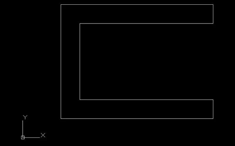
Direct Distance Method
This is the method which is different to the remaining 3 methods,where here we provide the distance of the line directly as per the name of the method.The distance of the line is to be given for the lines to be drawn to form an image.The provided distance is present on the screen near to the crosshair and is available even on the command bar where only just the distance is mentioned.Here,we have to adjust the cross hair position to get the image and using ortho mode is preferrable depending upon the diagram.
Initially,we use the LINE Command therafter by specifying the points.
- Specify the first point as (2,1).
- Specify the next point as 6.
- Specify the next point as 8.
- Specify the next point as 1.
- Specify the next point as 7.
- Specify the next point as 4.
- Specify the next point as 7.
- Specify the next point as 1.
- Specify the next point as (2,1) or by closing the drawing.
Result:
So,the given image is formed using the commands and specifying the points in AutoCAD.
Diagram 2(P 2)
Aim:
To the draw the given image by using all the coordinate systems.
Process:
We use the commands and specifying the various points by using all the various Coordinate Systems.
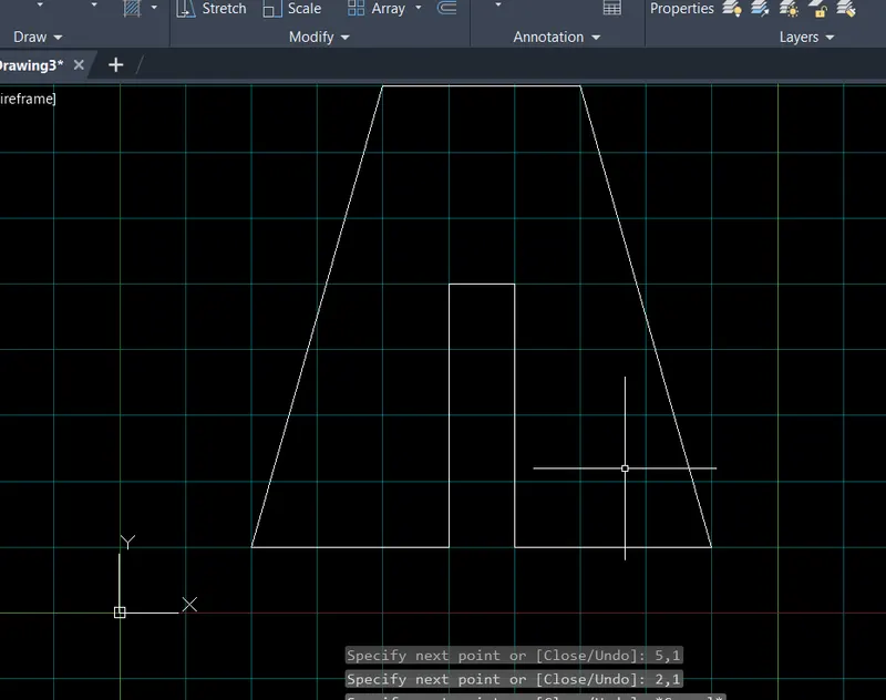
Absolute Coordinate System
Initially,we use the LINE Command thereafter by specifying the points.
- Specify the first point as (2,1).
- Specify the next point as (4,8).
- Specify the next point as (7,8).
- Specify the next point as (9,1).
- Specify the next point as (6,1).
- Specify the next point as (6,5).
- Specify the next point as (5,5).
- Specify the next point as (5,1).
- Specify the next point as (2,1) or by closing the drawing.
Relative Rectangular Coordinate System
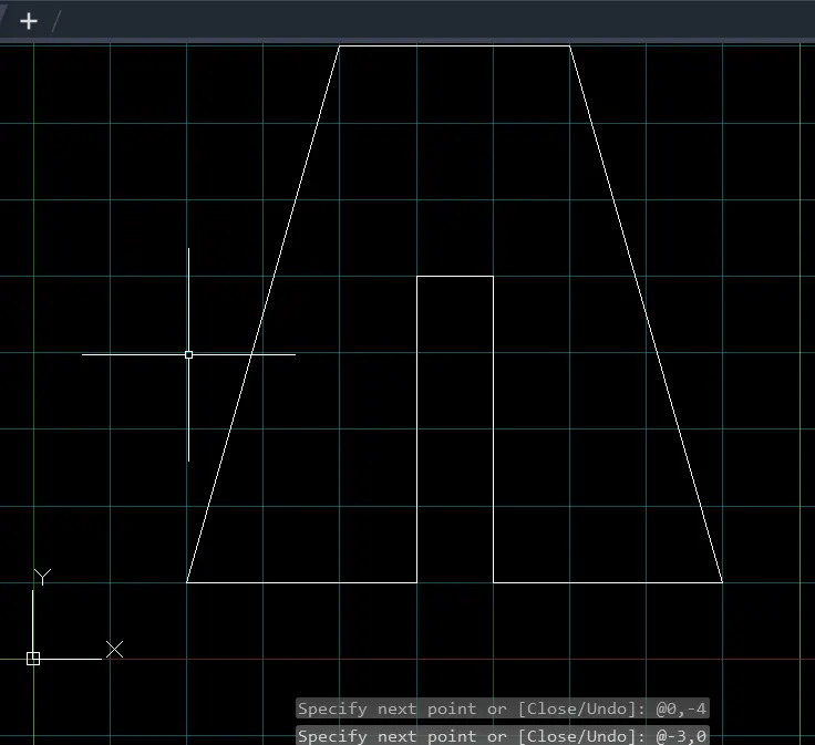
Initially,we use the LINE Command therafter by specifying the points.
- Specify the first point as (2,1).
- Specify the next point as (@2,7).
- Specify the next point as (@3,0).
- Specify the next point as (@2,-7).
- Specify the next point as (@-3,0).
- Specify the next point as (@0,4).
- Specify the next point as (@-1,0).
- Specify the next point as (@0,-4).
- Specify the next point as (@-3,0) or (2,1) by closing the drawing.
Relative Polar Coordinate System
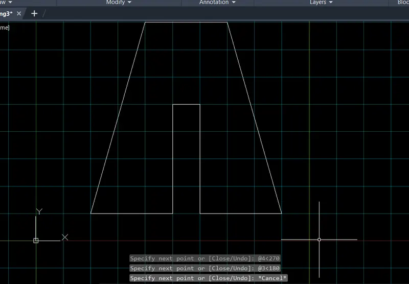
Initially,we use the LINE Command therafter by specifying the points.
- Specify the first point as (2,1).
- Specify the next point as (@7.28<74.05).
- Specify the next point as (@3<0).
- Specify the next point as (@7.28<285.95).
- Specify the next point as (@3<180).
- Specify the next point as (@4<90).
- Specify the next point as (@1<180).
- Specify the next point as (@4<270).
- Specify the next point as (@3<180) or (2,1) or by closing the drawing.
Direct Distance Method
This is the method which is different to the remaining 3 methods,where here we provide the distance of the line directly as per the name of the method.The distance of the line is to be given for the lines to be drawn to form an image.The provided distance is present on the screen near to the crosshair and is available even on the command bar where only just the distance is mentioned.Here,we have to adjust the cross hair position to get the image and using ortho mode is preferrable depending upon the diagram.
Here,for this diagram,we can't base upon only on the Direct Distance Method only,as adjusting the angles is difficult.SO,intially we have to draw the side slanting lines by any other method and then to proceed with this method to complete the remaining diagram.
So,here we draw the slanting lines by Absolute Coordinate System and the remaining by Direct Distance Method.
Initially,we use the LINE Command therafter by specifying the points.
Left Slanting Line
- Specify the first point as (2,1).
- Specify the next point as (4,8).
Right Slanting Line
- Specify the first point as (7,8).
- Specify the next point as (9,1).
Top Line
- Specify the first point as (4,8).
- Specify the next point as 3.
Bottom Line
- Specify the first point as (9,1).
- Specify the next point as 3.
- Specify the next point as 4.
- Specify the next point as 1.
- Specify the next point as 4.
- Specify the next point as 3 or (2,1).
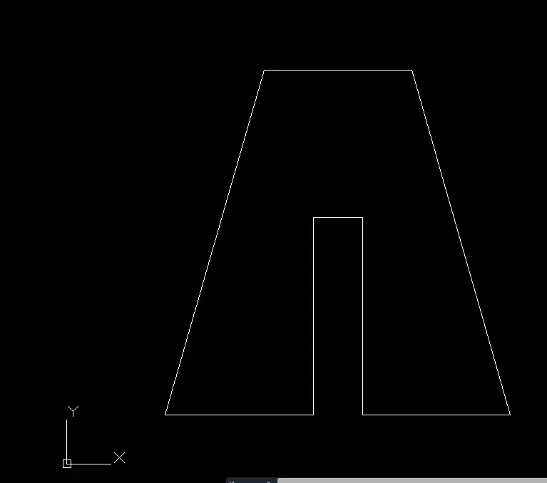
Result:
So,the given image is formed by using commands and specifying the points in AutoCAD.
Diagram 3(P 4)
Aim:
To the draw the given image by using any one of the coordinate systems.
Process:
We use the commands and specifying the various points by using the Absolute Coordinate System.
Initially,we use the LINE Command therafter by specifying the points.
- Specify the first point as (2,1).
- Specify the next point as (2,8).
- Specify the next point as (3,8).
- Specify the next point as (5,5).
- Specify the next point as (7,8).
- Specify the next point as (8,8).
- Specify the next point as (8,1).
- Specify the next point as (7,1).
- Specify the next point as (7,5).
- Specify the next point as (5,3).
- Specify the next point as (3,5).
- Specify the next point as (3,1).
- Specify the next point as (2,1) or by closing the drawing.
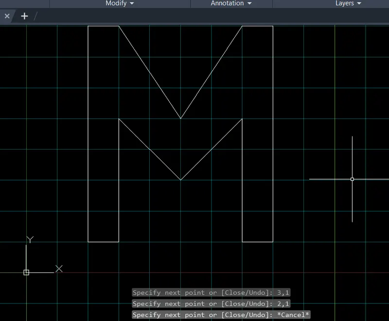
Result:
So,the given image is formed by using commands and specifying the points in AutoCAD.
Diagram 4(P 5)
Aim:
To the draw the given image by using any one of the coordinate systems.
Process:
We use the commands and specifying the various points by using the Relative Polar Coordinate System.
Initially,we use the LINE Command thereafter by specifying the points.
- Specify the first point as (2,1).
- Specify the next point as (@8<270).
- Specify the next point as (@7<0).
- Specify the next point as (@8<270).
- Specify the next point as (@4<180).
- Specify the next point as (@1<90).
- Specify the next point as (@3<0).
- Specify the next point as (@6<90).
- Specify the next point as (@5<180).
- Specify the next point as (@7<270).
- Specify the next point as (@1<180) or (2,1) or by closing the drawing.
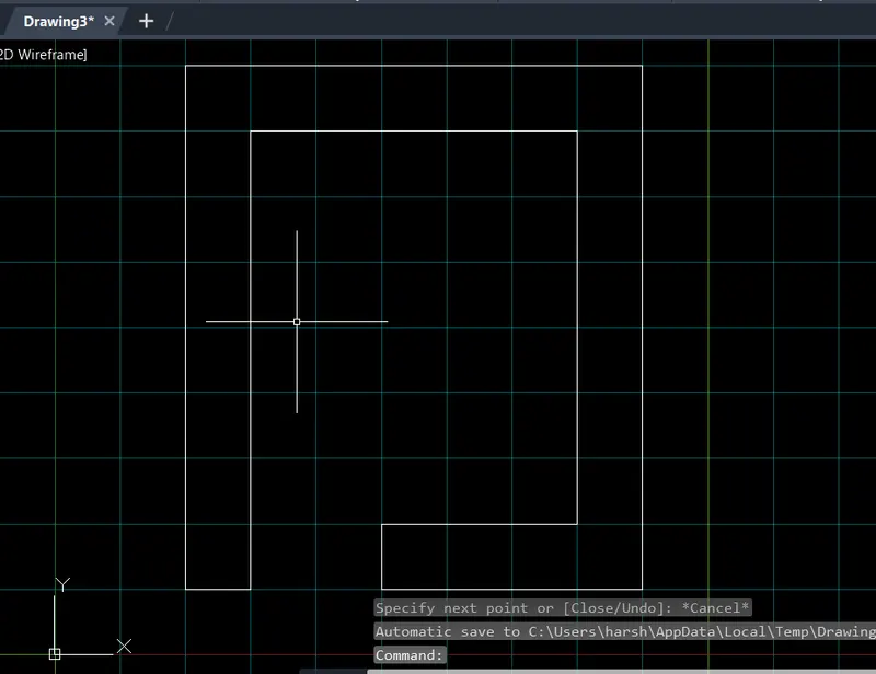
Result:
So,the given image is formed using the commands and specifying the points in AutoCAD.
Diagram 5(P 7)
Aim:
To the draw the given image by using any one of the coordinate systems.
Process:
We use the commands and specifying the various points by using the Relative Rectangular Coordinate System.
Initially,we use the LINE Command therafter by specifying the points.
We draw the outer box at first.
- Specify the first point as (2,1).
- Specify the next point as (@0,6).
- Specify the next point as (@8,0).
- Specify the next point as (@0,-6).
- Specify the next point as (@-8,0) or (2,1) or by closing the drawing.
Now,we draw the first inner box.
- Specify the first point as (3,2).
- Specify the next point as (@0,3).
- Specify the next point as (@2,0).
- Specify the next point as (@0,-3).
- Specify the next point as (@-2,0) or (3,2) or by closing the drawing.
Now,we draw the second inner box.
- Specify the first point as (6,2).
- Specify the next point as (@0,3).
- SPecify the next point as (@2,0).
- Specify the next point as (@-3,0).
- Specify the next point as (@-2,0) or (6,2) or by closing the drawing.
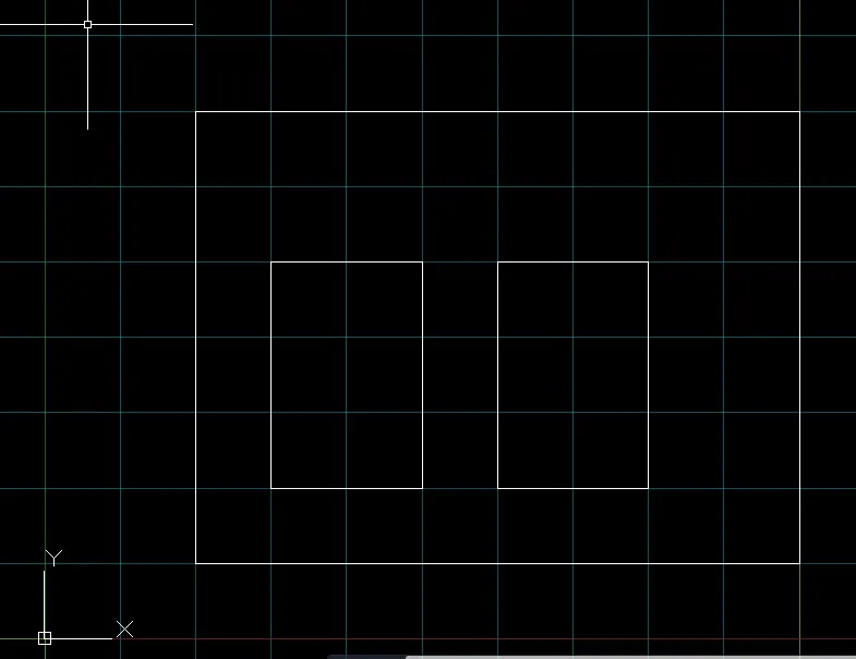
Result:
So,the given image is formed using the commands and specifying the points in AutoCAD.
Diagram 6(P 8)
Aim:
To the draw the given image by using any one of the coordinate systems.
Process:
We use the commands and specifying the various points by using the Relative Polar Coordinate System.
Initially,we use the LINE Command thereafter by specifying the points.
- Specify the first point as (0,0).
- Specify the next point as (@2<90).
- Specify the next point as (@4<0).
- Specify the next point as (@4<90).
- Specify the next point as (@3<180).
- Specify the next point as (@2<90).
- Specify the next point as (@8<0).
- Specify the next point as (@2<270).
- Specify the next point as (@3<180).
- Specify the next point as (@4<270).
- Specify the next point as (@4<0).
- Specify the next point as (@2<270).
- Specify the next point as (@10<180) or (0,0) or by closing the drawing.
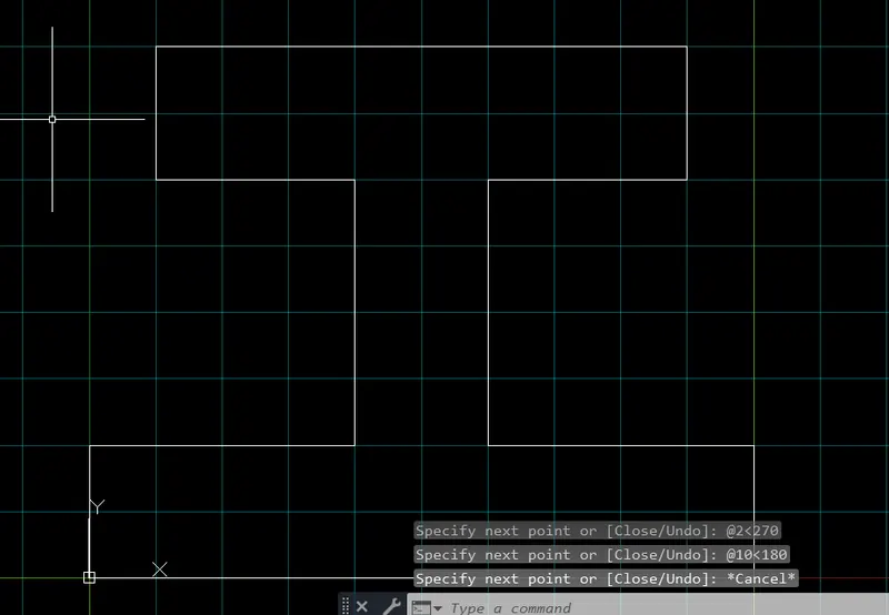
Result:
So,the given image is formed using the commands and specifying the points in AutoCAD.
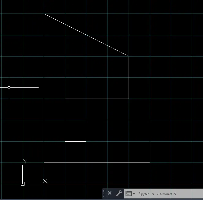
Diagram 7(P 9)
Aim:
To the draw the given image by using any one of the coordinate systems.
Process:
We use the commands and specifying the various points by using the Relative Rectangular Coordinate System.
Initially,we use the LINE Command therafter by specifying the points.
- Specify the first point as (1,1).
- Specify the next point as (@0,7).
- Specify the next point as (@4,-2).
- Specify the next point as (@0,-2).
- Specify the next point as (@-3,0).
- Specify the next point as (@0,-2).
- Specify the next point as (@1,0).
- Specify the next point as (@0,1).
- Specify the next point as (@3,0).
- Specify the next point as (@0,-2).
- Specify the next point as (@-5,0) or (1,1) or by closing the drawing.
Result:
So,the given image is formed using the commands and specifying the points in AutoCAD.
Diagram 8(P 10)
Aim:
To the draw the given image by using any one of the coordinate systems.
Process:
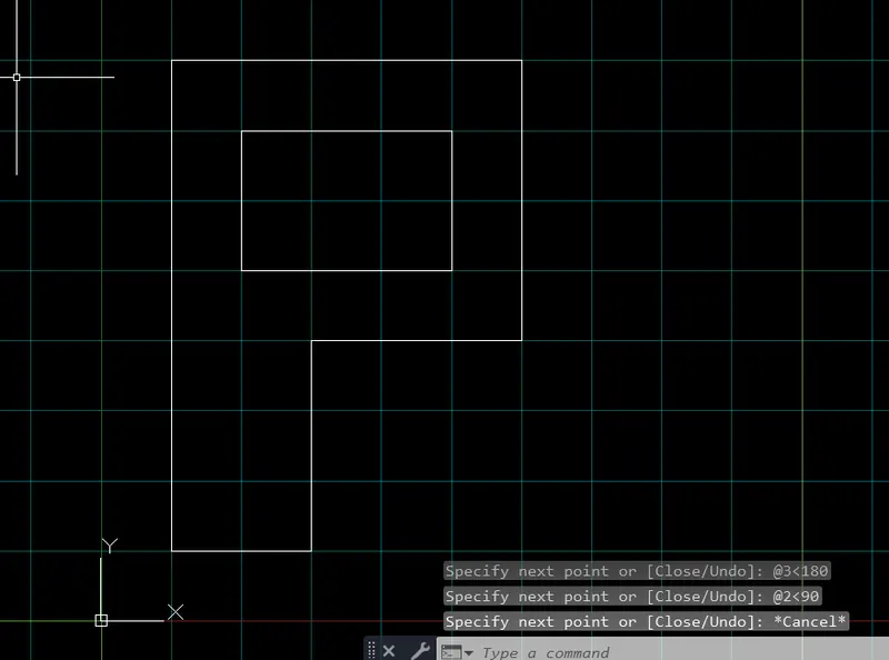
We use the commands and specifying the various points by using the Relative Polar Coordinate System.
Initially,we use the LINE Command thereafter by specifying the points.
We draw the outer box.
- Specify the first point as (1,1).
- Specify the next point as (@7<90).
- Specify the next point as (@5<0).
- Specify the next point as (@4<270).
- Specify the next point as (@3<180).
- Specify the next point as (@3<270).
- Specify the next point as (@2<180) or (1,1) or by closing the drawing.
We,now draw the inner box.
- Specify the first point as (2,7).
- Specify the next point as (@3<0).
- Specify the next point as (@2<270).
- Specify the next point as (@3<180).
- Specify the next point as (@2<90) or (2,7) or by closing the drawing.
Result:
So,the given image is formed using the commands and specifying the points in AutoCAD.
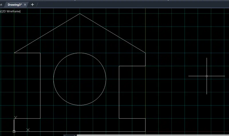
Civil Related Problem 1:Profile Wood
Aim:
To the draw the given image by using any one of the coordinate systems.
Process:
We use the commands and specifying the various points by using the Relative Rectangular Coordinate System.
Initially,we use the LINE Command therafter by specifying the points.
Firstly,we draw the outer house like structure.
- Specify the first point as (0,0).
- Specify the next point as (@0,1).
- Specify the next point as (@2,0).
- Specify the next point as (@0,5).
- Specify the next point as (@-2,0).
- Specify the next point as (@5,3).
- Specify the next point as (@5,-3).
- Specify the next point as (@0,-1).
- Specify the next point as (@-2,0).
- Specify the next point as (@0,-4).
- Specify the next point as (@2,0).
- Specify the next point as (@0,-1).
- Specify the next point as (@-10,0) or (0,0) or by closing the drawing.
Secondly,we draw the circle at middle.
We initiate the CIRCLE Command either by clicking on the Circle Image present on the Ribbon Bar or typing CIRCLE in the Command Bar or just by C+ENTER.
- Specify the first point as (5,4).
- Give the radius as 2.
Result:
So,the given image is formed using the commands and specifying the points in AutoCAD.
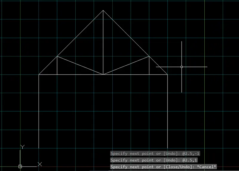
Civil Related Problem 2:Queen Post Truss
Aim:
To the draw the given image by using any one of the coordinate systems.
Process:
We use the commands and specifying the various points by using the Relative Rectangular Coordinate System.
Initially,we use the LINE Command therafter by specifying the points.
Firstly,we draw the bottom rectangular frame.
- Specify the first point as (1,1).
- Specify the next point as (@0,4).
- Specify the next point as (@7,0).
- Specify the next point as (@0,-4).
Now,we draw the 3 vertical pillars on the bottom rectangular frame.
Left Pillar
- Specify the first point as (2,5).
- Specify the next point as (@0,1).
Right Pillar
- Specify the first point as (7,5).
- Specify the next point as (@0,1).
Centre Pillar
- Specify the first point as (4.5,5).
- Specify the next point as (@0,3.5).
Triangular Frame
- Specify the first point as (1,5).
- Specify the next point as (@3.5,3.5).
- Specify the next point as (@3.5,-3.5).
Strut joining pillars
- Specify the first point as (2,6).
- Specify the next point as (@2.5,-1).
- Specify the next point as (@2.5,1).
Result:
So,the given image is formed using the commands and specifying the points in AutoCAD.
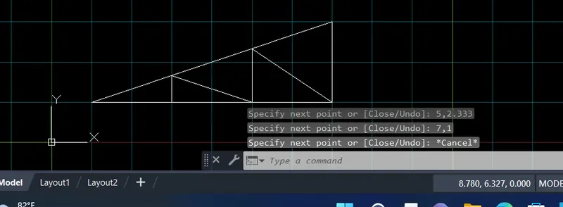
Civil Related Problem 3:Mono Pitch
Aim:
To the draw the given image by using any one of the coordinate systems.
Process:
We use the commands and specifying the various points by using the Absolute Coordinate System.
Initially,we use the LINE Command therafter by specifying the points.
Firstly,we draw the triangular frame.
- Specify the first point as (1,1).
- Specify the next point as (7,1).
- Specify the next point as (7,3).
- Specify the next point as (1,1) or by closing the drawing.
Now,we draw the pillars and struts.
- Specify the first point as (3,1).
- Specify the next point as (3,1.667).
- Specify the first point as (5,1).
- Specify the next point as (5,2.333)
- Specify the first point as (7,1).
Result:
So,the given image is formed using the commands and specifying the points in AutoCAD.
Result:Hence,the given images are drawn in AutoCAD using the necessary commands and specifying the require points.