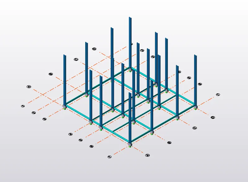
To model columns for industrial steel structure using TSD
1)
Aim - To create column properties for different types of pedestal members and model in the grids created as per the assignment 1
Introduction -
i) Tekla Structural Designer is an BIM -integrated model-based 3D software for analysis and design of structures.
ii) It includees modeling, automated structural analysis and design, drawing, and report creation.
iii) Column positions in the layout as per input drawings considering the openings.
iv) To provide expansion joints as per IS: 800:2007
v) Provide primary beams to tie columns and break the effective length
vi) Provide seondary beams to support floor and brick wall.
vii) Plan the moment connections framing and provide bracing bracings for lateral stability
Procedure -
1) Geometry
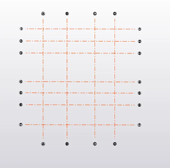
i) First we have to create the grid lines according to the given input drawings
ii) After creation of grid lines , next step is to Define the settings
iii) Next Step is to Define the Material Properties
iv) Once this primary steps are done we can go for Modeling
2) Modeling
i) Add the Construction Levels as per drawing
ii) Place the column according to the given position as per drawings
iii) Similarly place the primary beams as well as secondary beams
iv) Do the validation step by step to avoid further errors .
Step 1)
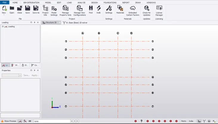
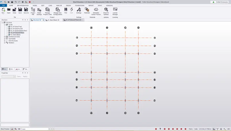
i) Open the Assignmenrt 1 file
ii) Where we have already created the grid lines
iii) We already set the settings in Week 1
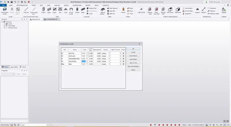
iv) Just check the Construction levels
v) Construction Levels are okay.
Step 2) Creation of Properties
i) As this is a steel building Steel columns are going to rest on Padestal column
ii) So go to Home tab - Manage property Set
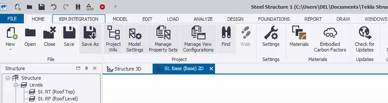
iii) Click on Manage property set a following dialog box will appear
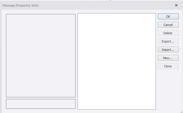
iv) Click on New - Members - Concrete Column
v) Rename as PD1
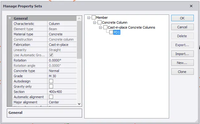
vi) Once property is defined
vii) Go to Model - Click on Column
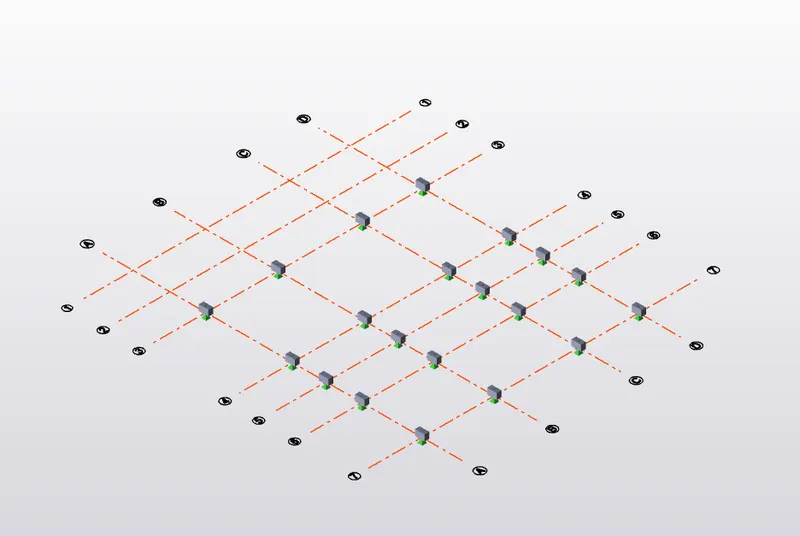
viii) Placed the columns as shown below
ix) Change the level frome Base to GF
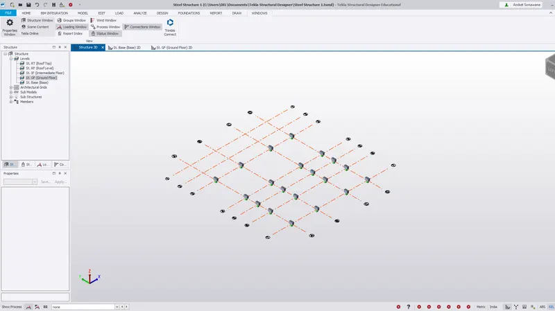
Result - A pedestal column is created as per drawing from base to Ground Floor level
2)
Aim - To create column properties for steel columns and model columns in the grid created as per assignment 1.
Procedure -
i) Once the Pedestal Column is assigned
ii) Now we have to assign Steel Columns
iii) Go to Manage Property Set - New - Members - Steel Column
iv) Rename - C1
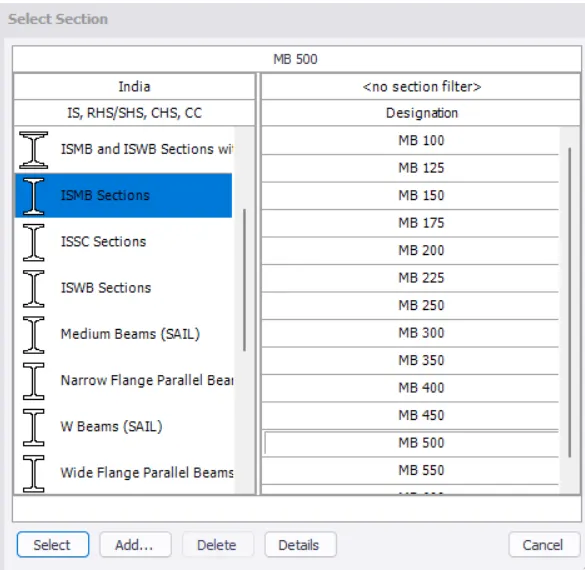
v) Select property as ISMB - 500
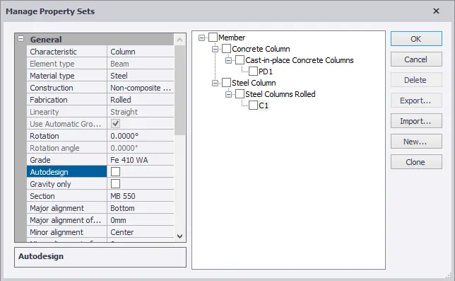
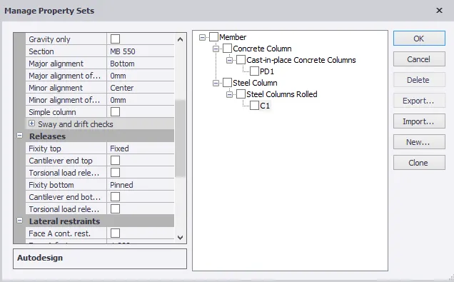
vi) Change the Fixity - Pinned at Bottom
Fixed at Top
vii) Chang the Major Alignmene as Bottom
viii) Once the Property is defined
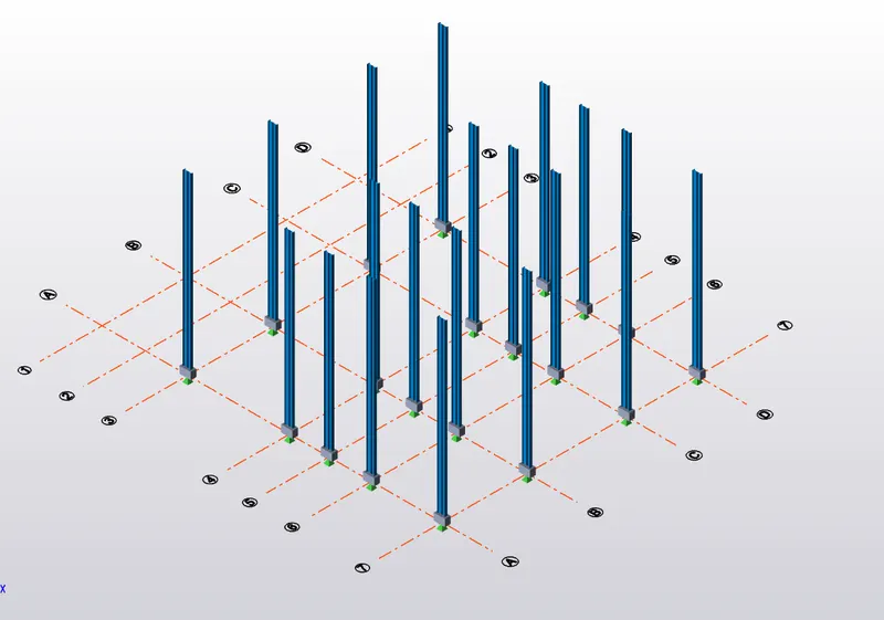
ix) Go to Model - Steel Column - Select propert as C1 from Properties window and assign
x) Select level from Ground Floor - Roof Level
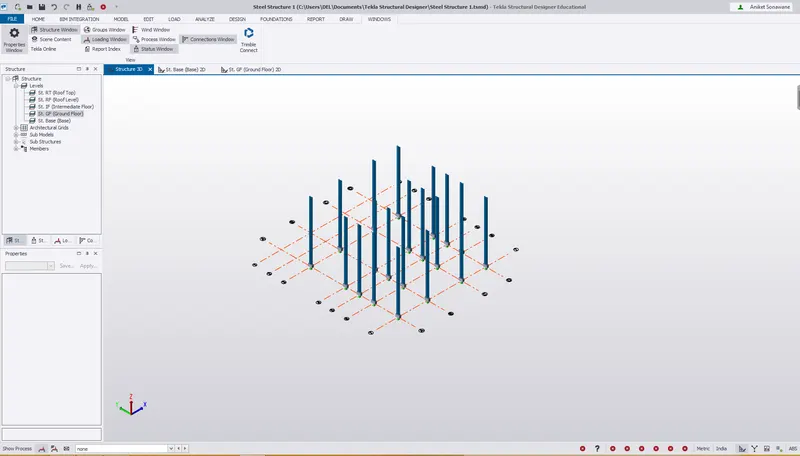
Results - A Steel Beam is created as per the drawing from Ground Floor to Roof level .
3)
Aim - To create beam properties and model primary and secondary beams on the ground floor
Procedure -
i) Once the Column is defined
ii) Now we have to defined primary and secondary beams for ground floor
iii) Go to Manage Property Set - New - Members - Steel Beam
iv) Rename - B1
v) Select property as ISMB - 350
vi) Primary Beams are created
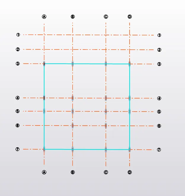
vii) Similarly create Secondary Beam
viii) Rename it as B2
ix) Section ISMB - 250
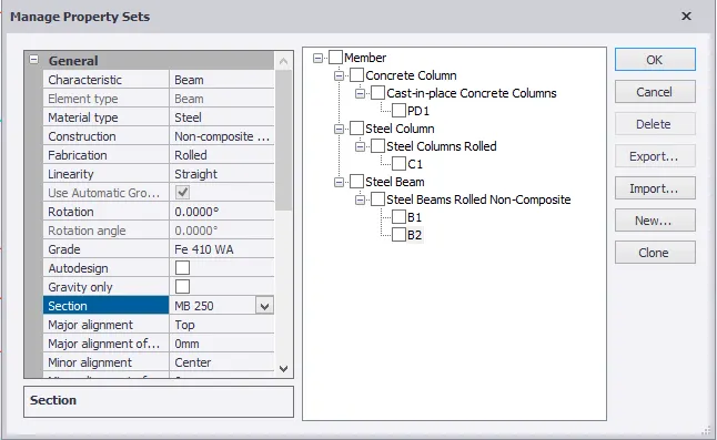
x) Once property is defined
xi) Go to - Model - Steel Beam
xii) Assign it as follows
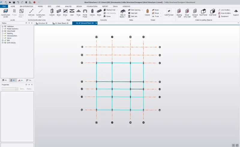
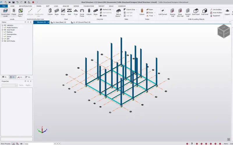
xiii) Now Validate our model - As there is no error in Model Geometry.

xiv) Solver View - We can check our model in solver view also to check any error .
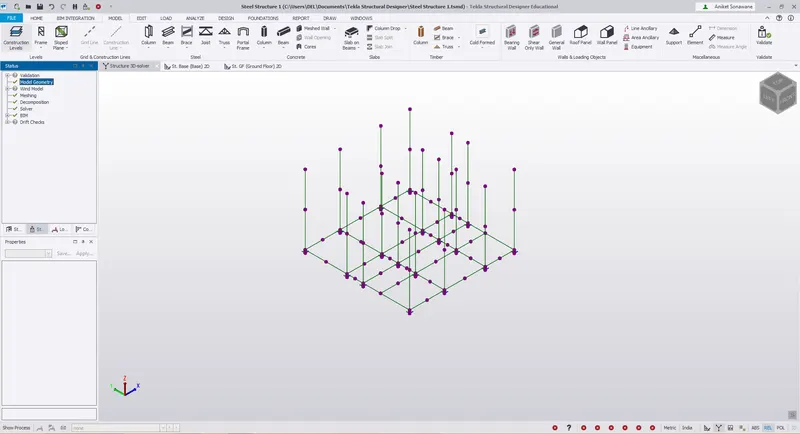
Results -
i) Created column properties for different types of pedestal members and model in the grids.
ii) Created column properties for steel columns and model columns in the grid created.
iii) Create beam properties and model primary and secondary beams on the ground floor