To model beams and bracings for industrial steel structures using TSD
1)
Aim - To create beam properties for First floor and model the beams
Introduction -
i) The main function of beam is to carry the loads from the slabs or any secondary beam and transfer it to the column.
ii) Inorder to create beam properties for first floor, make sure that it matches the ground floor
beams and then proceed to the modelling part
Procedure -
Step 1)
i) Open the previous file on which we were working on week 2
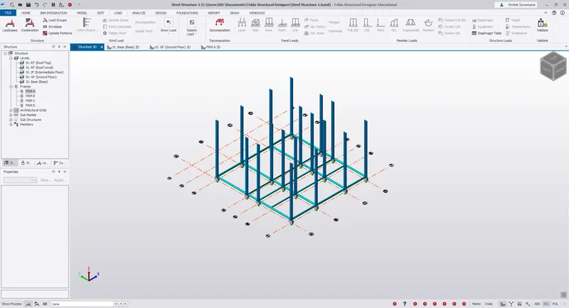
ii) Follow the same procedure to create properties for 1st floor
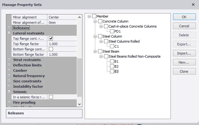
iii) Click on Home -Manage Property set
iv) Click on New - Member - Steel beam
v) Rename it as B3
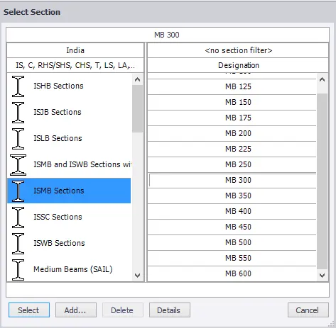
vi) Assign the Section as ISMB 300
Step 2)
i) As the property is defined
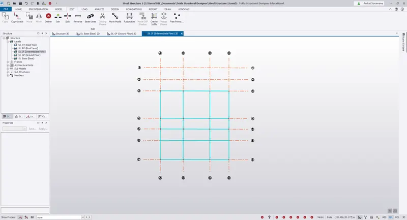
ii) Open the First floor attachments
iii) and Add the Primary beams as shown below
Step 3)
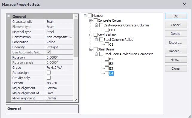
i) Similarly create the properties for Secondary beams also
ii) Click on Home -Manage Property set
iii) Click on New - Member - Steel beam
iv) Rename it as B4
vi) Assign the Section as ISMB 250
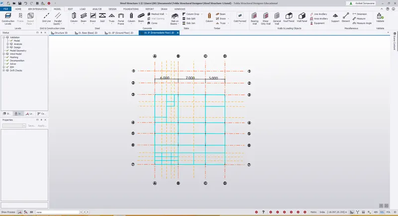
vii) Open the 1st floor plan and add the secondary beams
viii) Dimensions are given in floor plan
ix) Draw the Construction lines to make it easier to draw secondary beams.
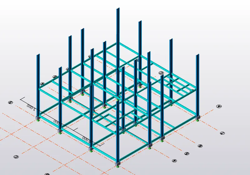
x) Check the model or Validate the model to see if an error is present or not
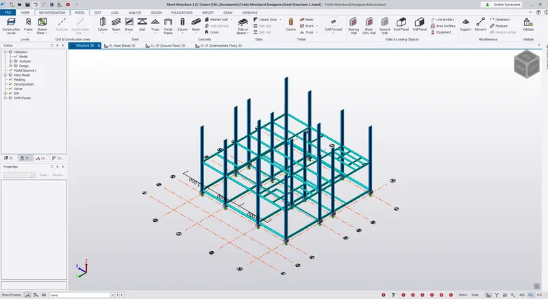
xi) No error , Hence modeling is okay .
Step 4)
i) As the beams are modeled for Ground floor , 1st Floor
ii) We have to create a beams for Roof level also
iii) So similary create the primary beams for Roof level
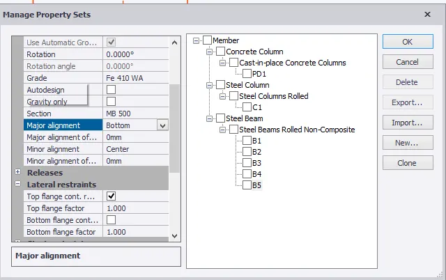
iv) Go to Home - Manage Property Set - Member - Steel Beams
v) Rename it as B5
vi) Assign section ISMB - 500
vii) Draw the beams similarly to previous levels
viii) Primary beams are drawn on Roof Level
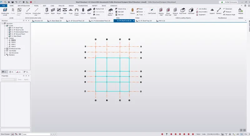
ix) Check the model to validate - No error
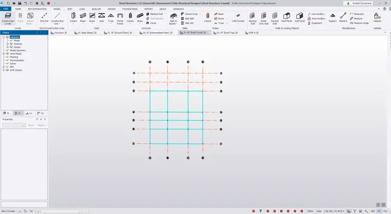
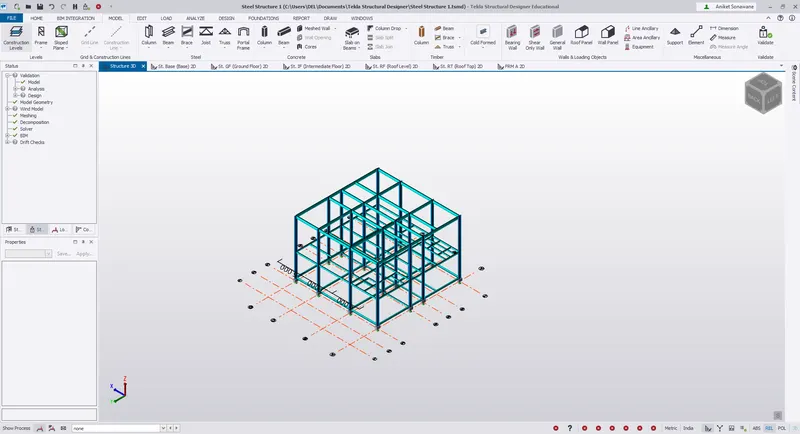
Result - A beam properties are created and assigned to the model
2)
Aim - To create rafter beam on second floor as roof and moment frame action in one direction and add bracings at locations
as per the design intent.
Introduction -
i) A rafter is a structural component that is used
ii) Typically, it runs from the ridge or hip of the roof to the wall plate of the external wall.
iii) Rafters are generally laid in series, side by side, providing a base to support decks, roof coverings and so on
Procedure -
Step 1)
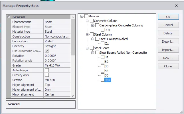
i) For Rafter first we have to create the Rafter properties
ii) Home - Manage property set - Member - Steel beam
iii) Rename it as - RB1
iv) Select section as - ISMB 550
Step 2)
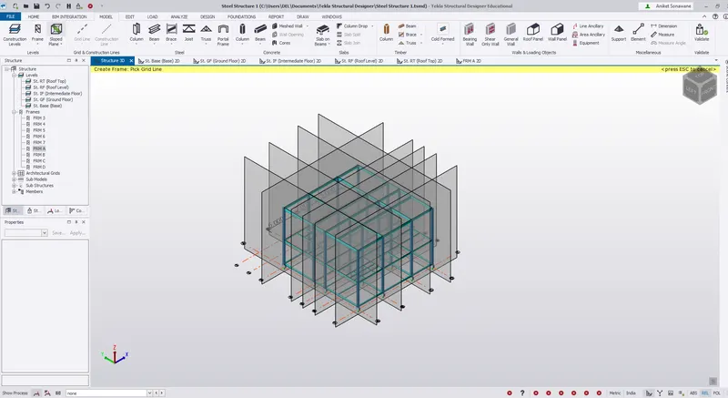
i) Create a Frame so that it will be easier to see the cross sections
ii) Go to Model - Frame
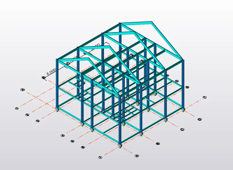
iii) Create a frames on grid lines as shown below
iv) Click on Frame A to draw the rafter
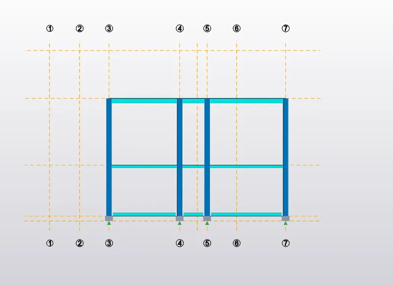
v) Draw the Rafter by picking up the points
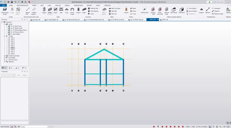
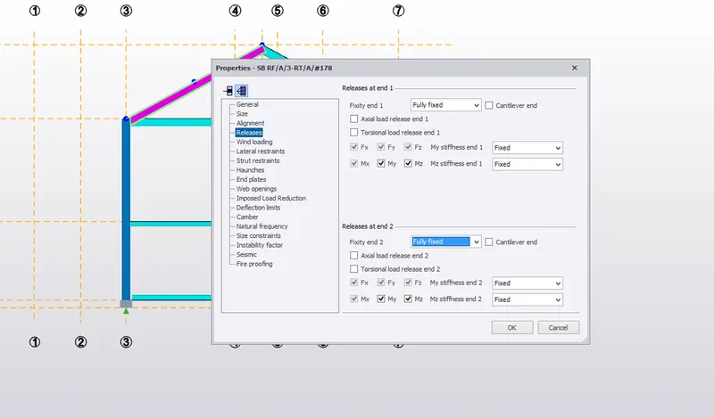
vi) Change the property of Rafter from pin to Full Fixed
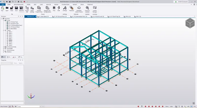
vii) Copy the Rafter beams to another frames by picking up the reference beams
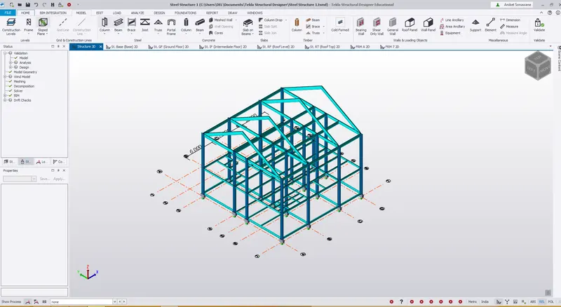
viii) Validate the model to check the error
Step 3) Bracing
i) Follow the same procdure to create bracing properties
iii) Home - Manage property set - Member - Steel brace
iii) Rename it as - BR1
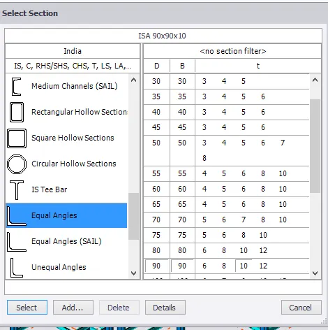
iv) Select section as - ISA 90 x 90 x 10
v) Now go to Model - Steel Brace - select X bracing and apply
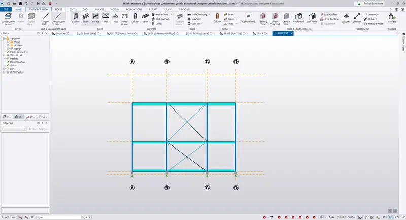
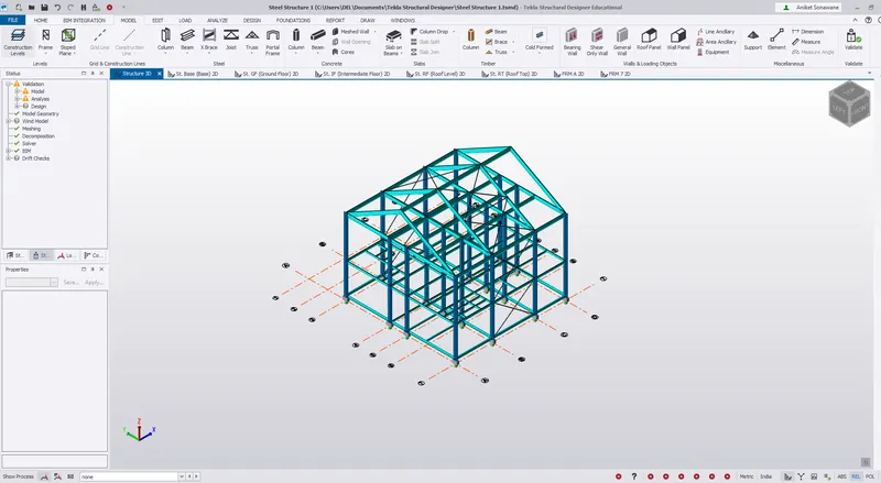
vi) Similalry we have to apply bracings on Roof also
vi) Select the X bracing and draw the bracings on Roof also.
Step 4) Creation of wall Panel and Roof panel
i) Wall panels are created to distribute the lateral load uniformly
ii) Go to Model - Wall panel
iii) Select the Frame 3 anf Frame 7 and draw the wall panel
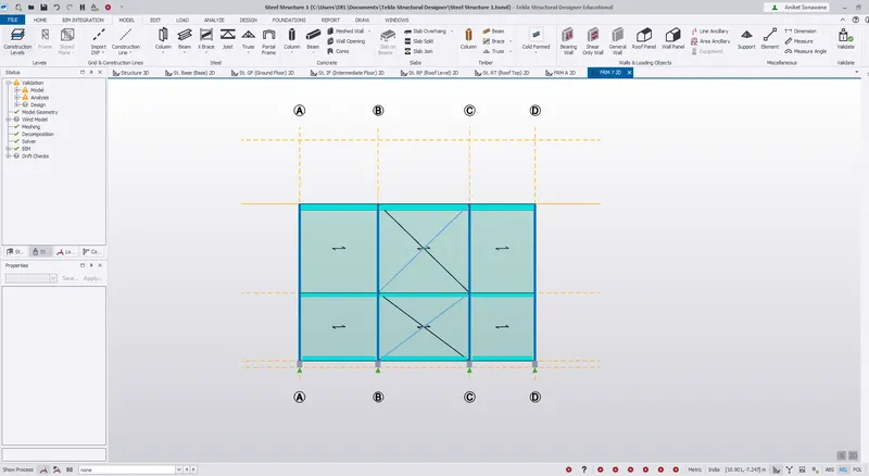
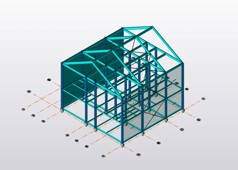
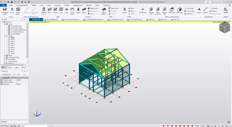
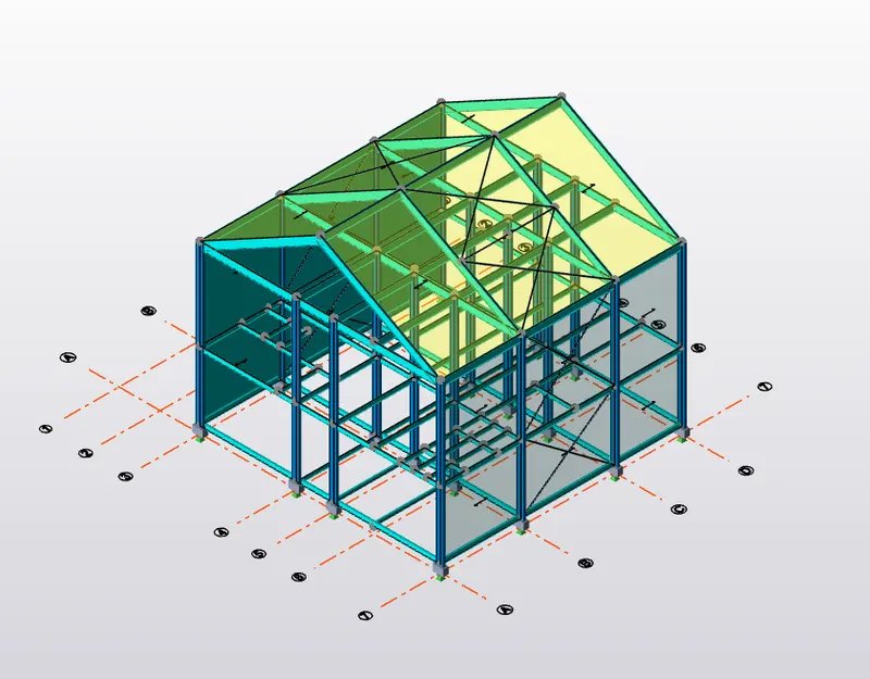
iv) Similarly draw the roof panel also.
v) Pick up the reference point and draw rooof panel also.
Step 5) Slab Properties -
i) Slab properties is next to designed
ii) For that click on Manage property sets options and the manage property sets dialogue box appears.
iii) Click on New followed by members and select Slabs followed by general slab item.
iv) Rename it as S1 and S2
v) S1 = One way slab
vi) S2 = Two way slab
Slab properties:
i) Grade M25
ii) Overall Depth 200mm
iii) Rotation 90 degree
iv) One way and Two-way slab were modelled with the same properties.
And can be distinguished by taking the Lx/Ly ratios
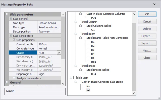
v) Slab property has been assigned to each level .
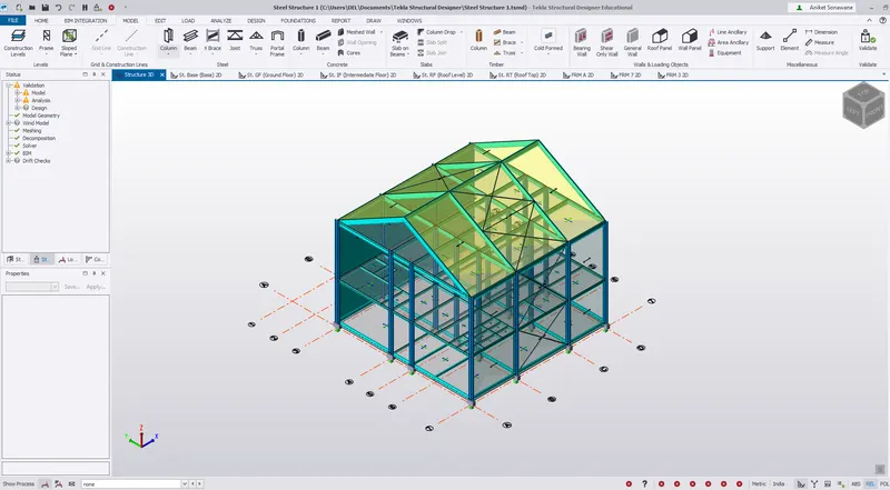
Results -
1) Rafter Beam is designed and modelled
2) Steel Bracings is modelled
3) Wall Panel and Roof Panel is designed and modeled
4) Slab property is designed for all floors