To Model a RC residential structure using TSD
1)
Aim - To setup the cover for RC building
Introduction -
i) As per IS 456 :2000 the covers are provided to prevent the reinforcement from enviromental effects
ii) Concrete covering is provided to prevent corrosion of reinforcement bar in RCC.
iii) Reinforcement is prone to fire and corrosion due to atmospheric conditions.
iv) Therefore Cover is required to avoid the enviromental effects.
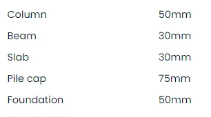
v) As per IS 456:200 minimum cover are -
Procedure -
Step 1)
i) Open the TSD- Click on New file and Rename it Go to Home – Settings
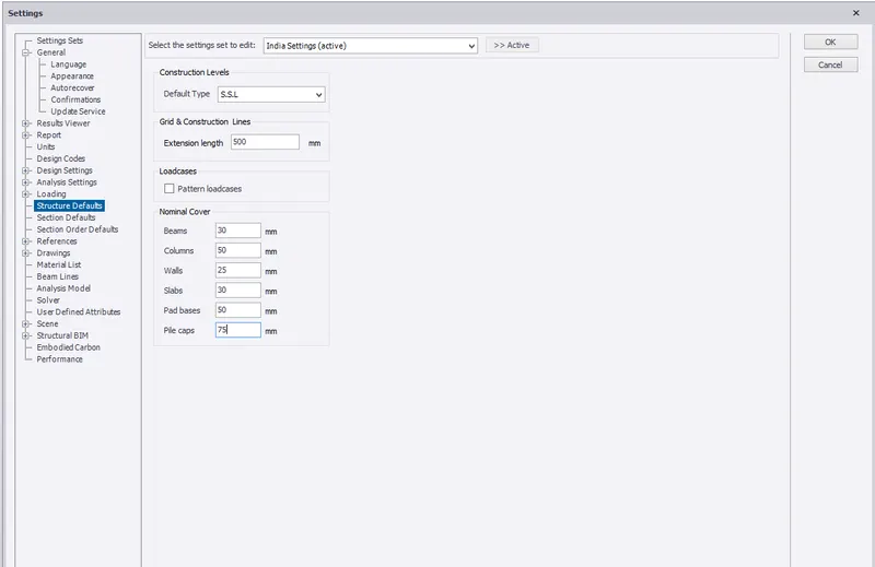
ii) Now go to Home – Click on Settings - Structure defaults.
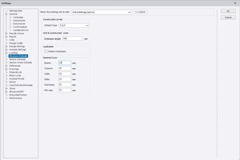
iii) Structural default type as TOF/SSL and accordingly adjust the cover.
i) For Cover Contact with ground - Select SSL
ii) For Above ground - TFL
Result - i) The concrete cover setting has done in TSD.
2)
Aim - To model the grids as per the given attachment
Introduction -
i) The first step in any modelling is to model the grids horizontally and vertically.
ii) Once the grid lines are created, its easy to model beams and columns over the gridlines
Procedure -
Step 1)
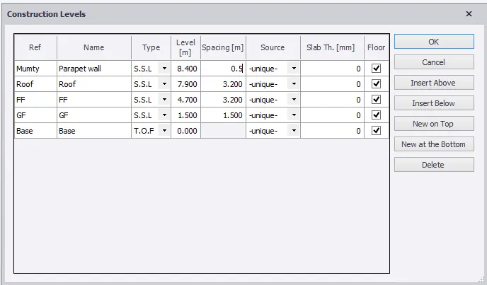
ii) Once model is open we have to define the Constuction levels.
iii) For that go to Model – Construction levels - Ente the level
Step 2)
i) Now go to GF to model the grids by using Model – Grid Line option
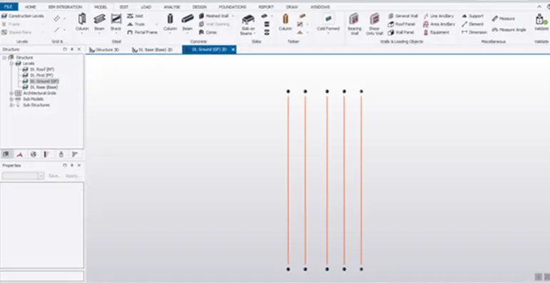
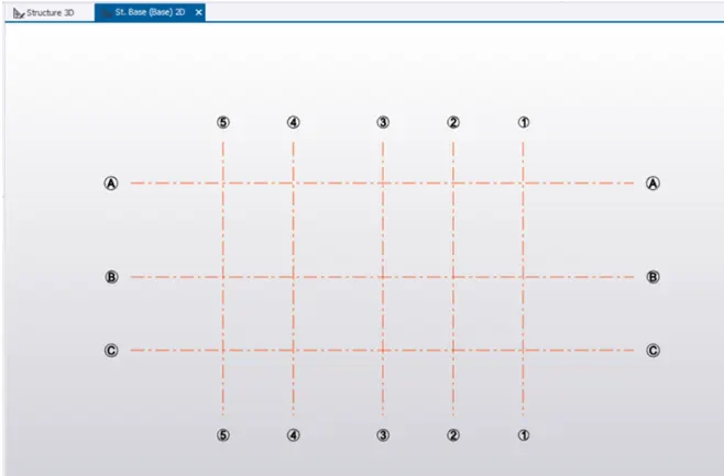
ii) Use perpendicular grid line option to model horizontal grid line.
iii) Then go to Model – Check the dimension as per drawing.
Result -
i) The vertical and horizontal grids are modelled as per the drawings.
3)
Aim - To study the layout and write a summary for general arrangement of the structure
Introduction -
i) Reading the structural drawing is very necessary before we start analysing the structure.
ii) It helps us take some important Engineering decisions like position of columns,beams etc.
Procedure -
Step 1) Genral arrangement
i) Before starting any design 1st step is to study the structural layout of the plan.
ii) Check the position of columns and beams which are given from architect
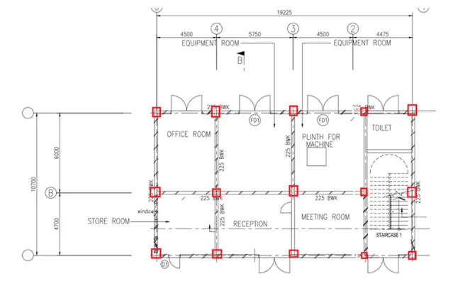
iii) Mark the position of Columns in drawing as per necessity
iv) Column position is marked for given attachments as shown below
Step 2)
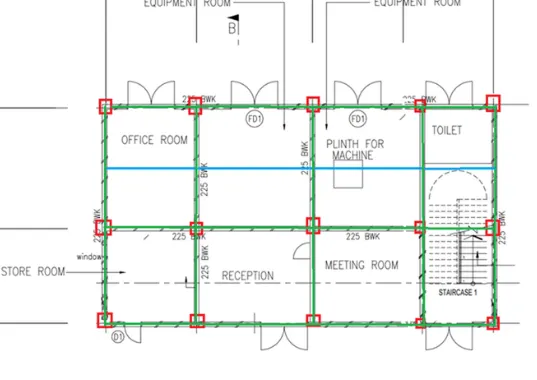
i) Similarly beams are also shown
ii) Secondary beams are shown as the span of 6000 mm.
iii) Secondary beams are designed as simply supported beams.
Step 3) Summary
i) The height of the GF is 1.5 m form the base (assume).
ii) Ground floor to First Floor is 3.2m.
iii) First Foor to Roof is 3.2m
iv) Roof to Paraper wall 0.5m
v) The ground floor plan is of size 19.225 * 10.7 m
vi) The columns are marked as per shown in Step 2
vii) The brickwall thickness is mentioned as 225mm
Result -
i) The structural drawing is studied for various levels of floors, grid spacing, column and beam positioning
4)
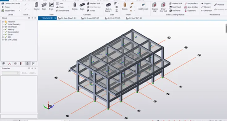
Aim - To model RC columns, beams and slabs as per the given plan.
Procedure -
Step 1)
i) Open the previous model.
ii) Go to Manage Property sets and create new concrete column
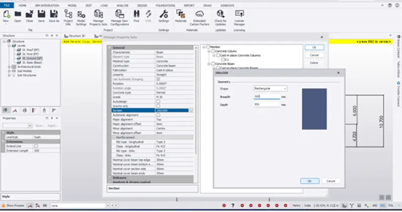
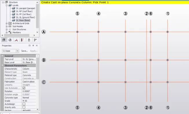
iii) Now go to Base level and Select Top level as Ground Floor.
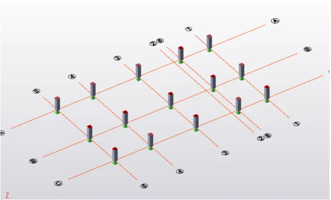
iv) Go to Model - Select Column and placed the column as shown below
Step 2) Beams -
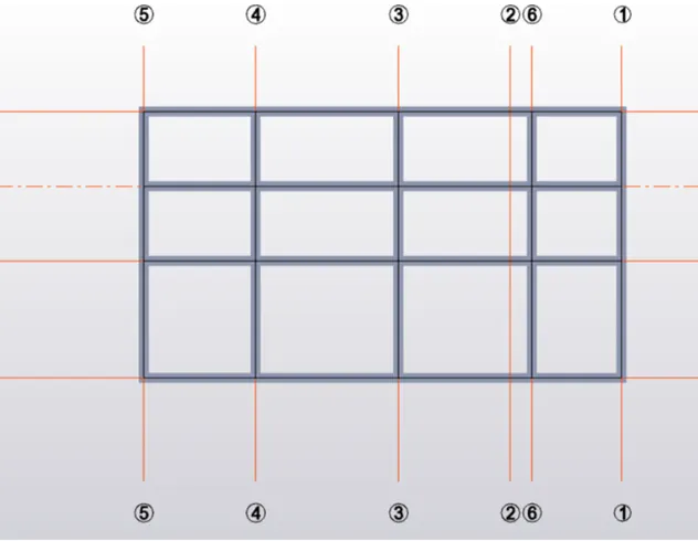
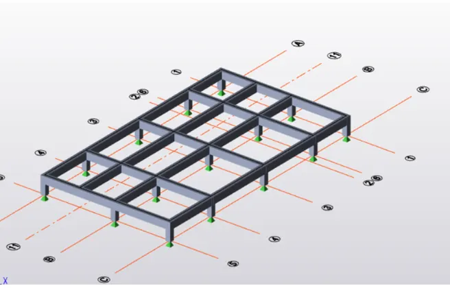
i) Now we have to model the beams.
ii) Go to manage property - Click on New - Member - Concrete Beam - Give the approximate size = 400 x 600 mm.
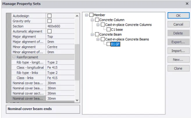
iii) Once property is defined. Go to Model - Concrete beam and add the beams as shown below
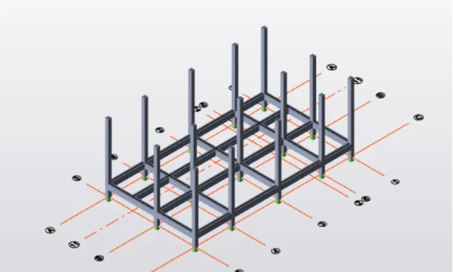
iv) Now we have to provide column to the upper level with different cover
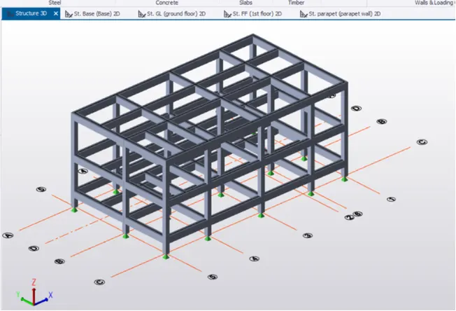
v) Now copy the same beams arrangement to first floor and Roof level also .
Step 3) Slabs
i) Now we have to define the slabs
ii) Go to manage property - Click on New - Slabs
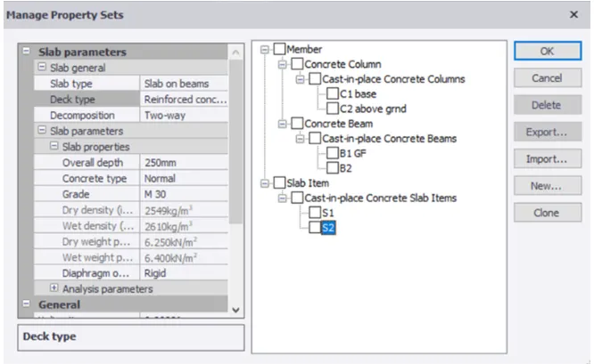
iii) Now go to Ground Floor - Select the slabs on beams -
iv) Apply the slab except staircase portion.
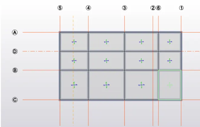
Step 4) Corridor
i) We have to define the corridor portion also
ii) For that we have to create the cantilever slab and beam .
iii) Click on Manage Property Set - New Member - Concrete Beam - and Give Releases as Cantilever end 2
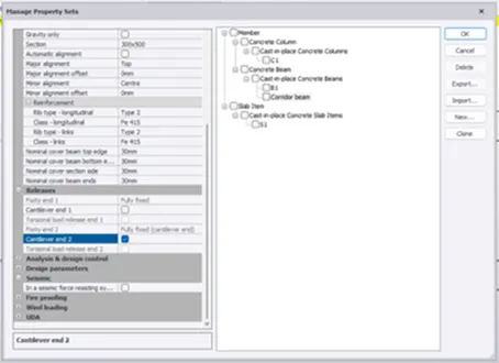
iv) Add the Corridor Slab as One way slab
v) Corridor slab will be on only First Floor
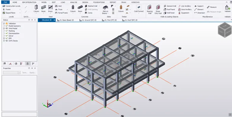
vi) Model the slab as shown below
Step 5) Validation -
i) Check the model if any modeling error is there or not
ii) Click on Validate the model .
Result -
i) The RC beams, columns and slabs are modelled according to the given drawings and Model is also Validated.