To Generate seismic loading based on IS code and to run the analysis using TSD
1)
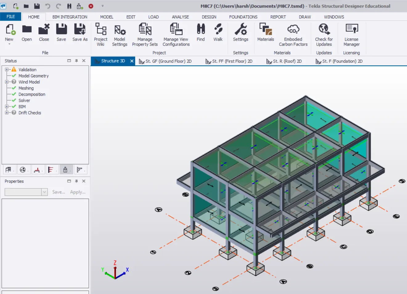
Initially,we open the file.
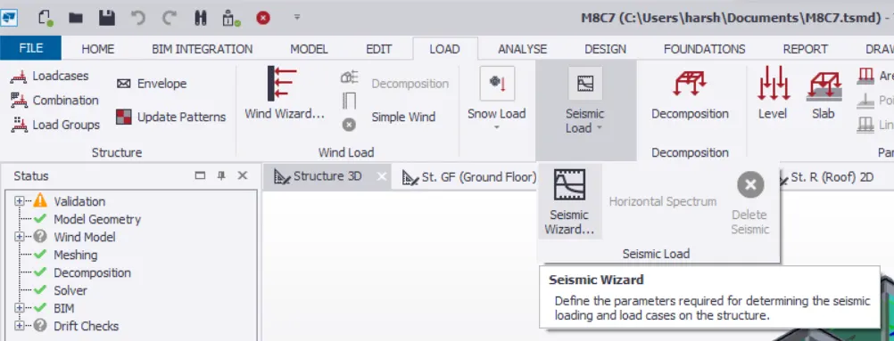
Then we go to LOAD Tab>Seismic Load>Seismic Wizard.
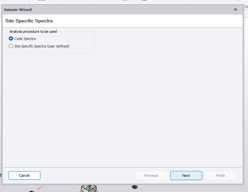
As we design basing upon the IS Code,we continue with the Code Spectra option in the resultant tab.
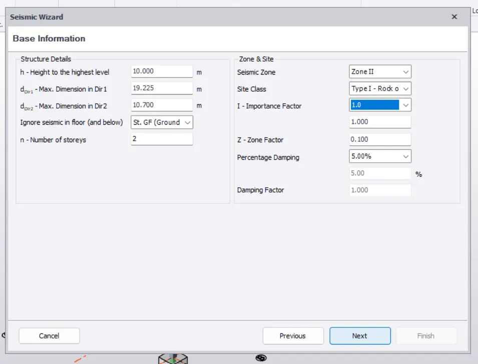
Where the dimensions are automatically considered and we give the further details such Zone 2,which was mentioned in the question and we select the Rock/Hard Soil and the Importance Factor as 1 and the Damping Ratio as 5% where the no. of storeys available are 2 where we select the base floor as GF(Ground Floor) where below which we don't consider the seismic impact.
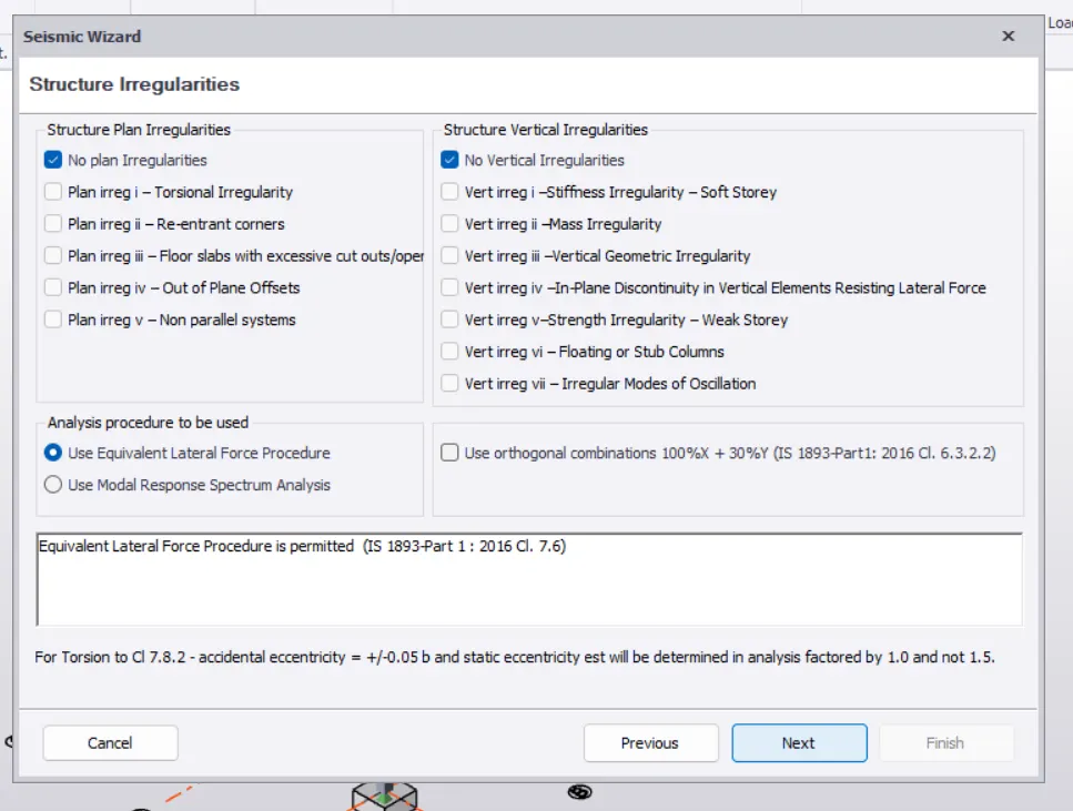
And as our model as no irregularities,we continue with that where we use the option of Use Equivalent Lateral Force Procedure as we use that the most common.
And then we continue with the further.
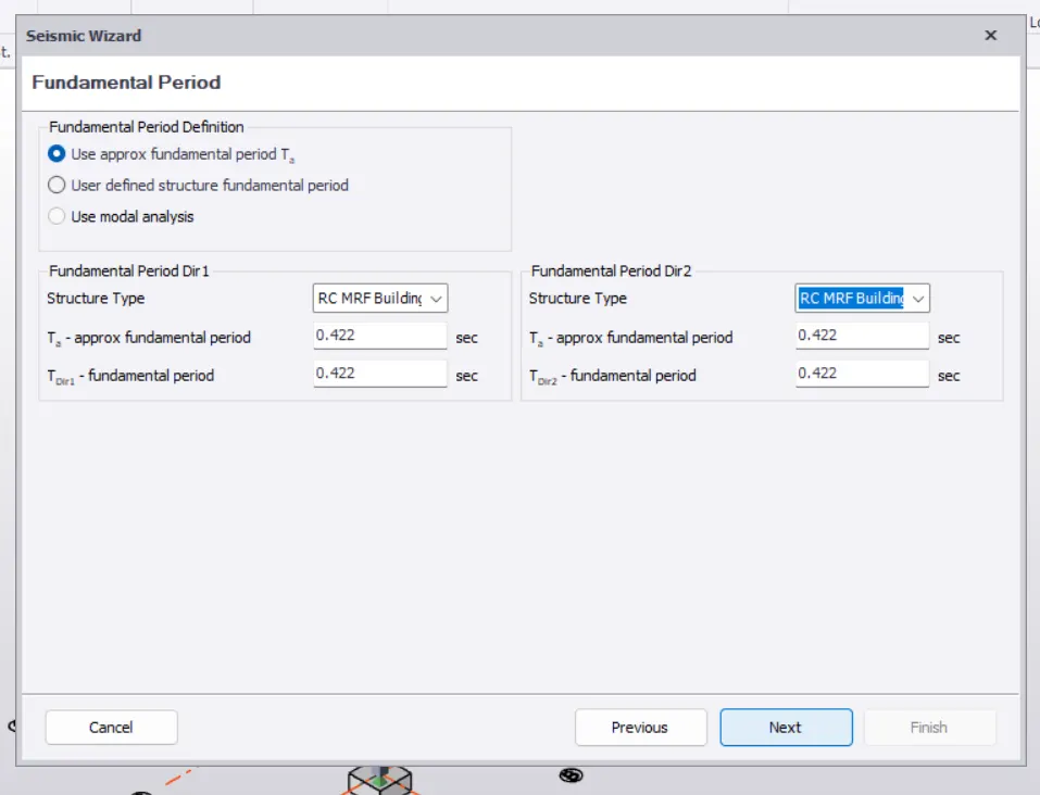
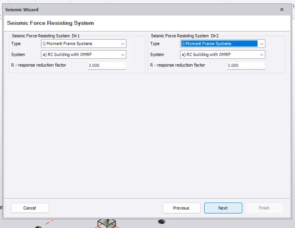
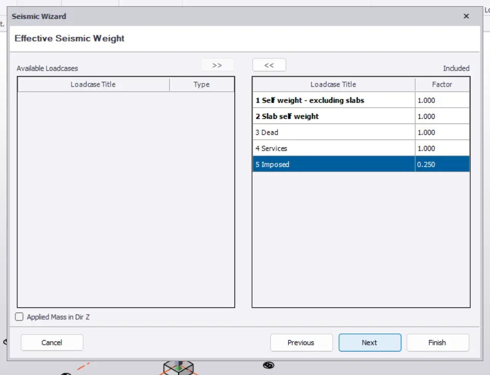
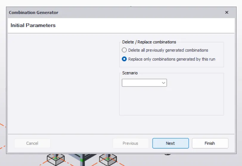
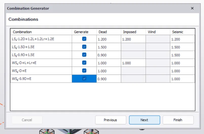
And we select the required load cases.
2)
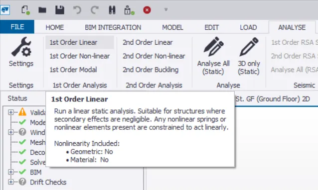
We then go to the ANALYSE Tab>1st Order Linear option.
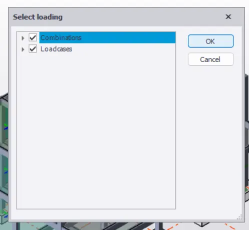
We select all the combinations and the loads.
Then in the we can select the required diagram in Results<RESULTS Tab,such that we can view it.
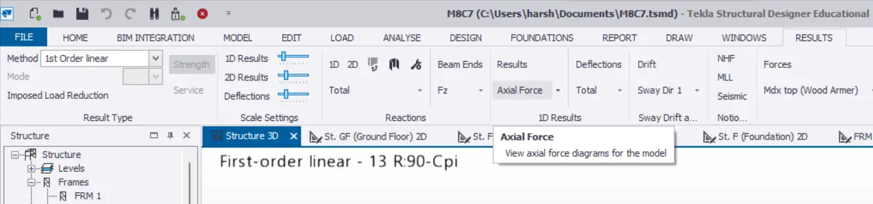
The below is the Axial Load Diagram.
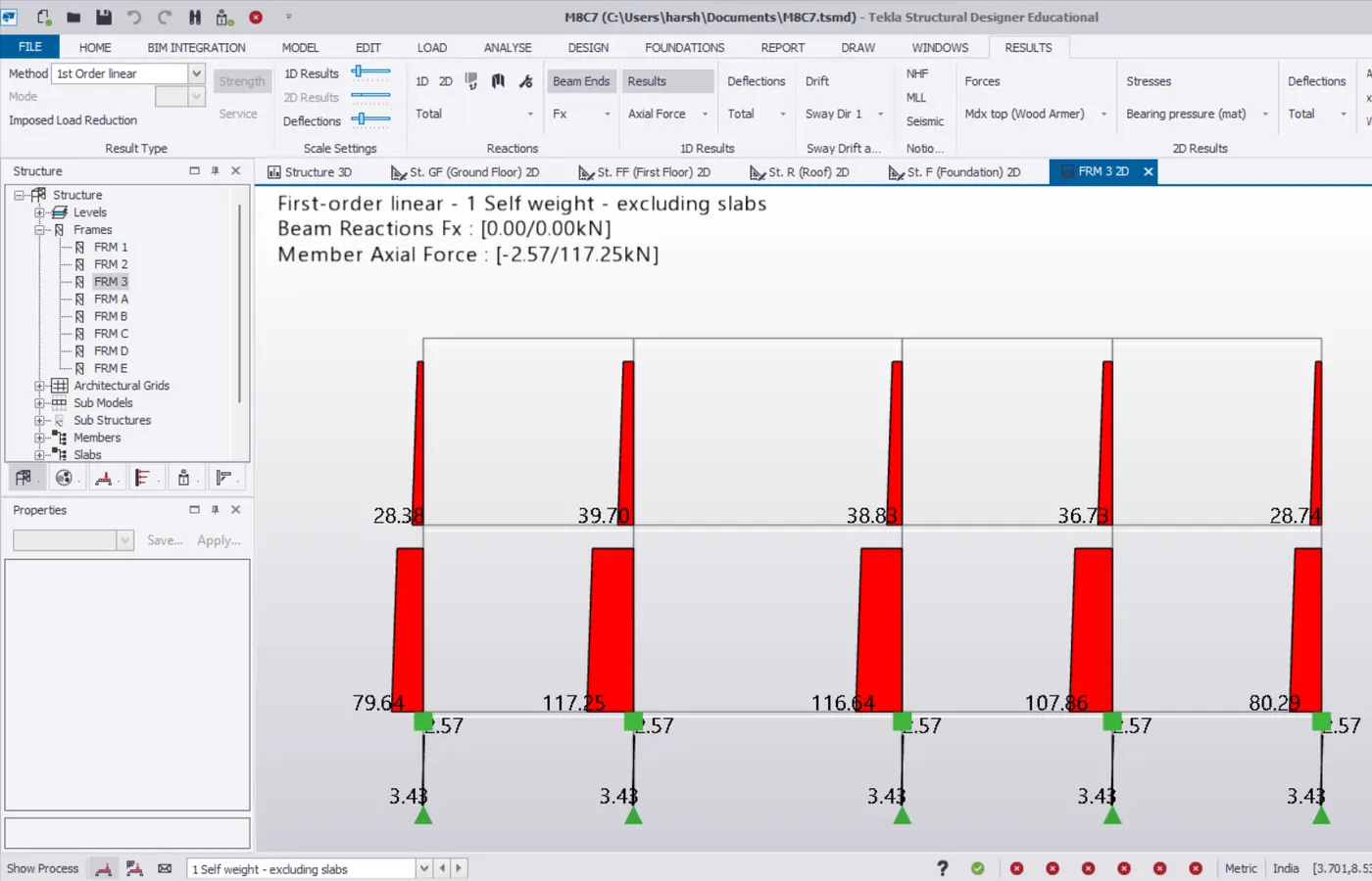
From the above diagram,we can find that the axial load increases as we move from top to bottom which indicates the correct load passage,as the weight increase at the bottom of the column than at the top of it.On the columns of the first floor,only the weight of the beams do fall as per this load case,whereas on the bottom column,the weight of the beams of both the floors and even the weight of the upper columns do fall on these,that's the reason why we can find very huge variation on the axial forces acting on the columns of both stories.
The below is the Shear Force Diagram.
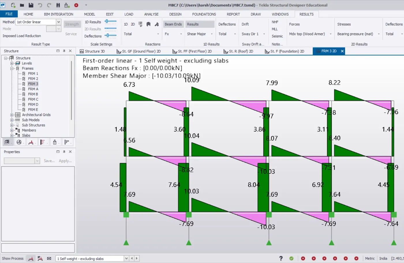
From the above image,we can find the shear force acting on the members for the same frame as well as for the same load case.We can find that beams at every bay do have near by values of the shear force acting on it as here the beams are only subjected to their self weight,as the same sections are used for the all,the values are also near by.In the second bay from left where the length of the beam increases the self weight too increases,so the shear force acting on the beam also will be increasing which is what represented from the above where the value at those bays are high.
The columns too have the same SFD indicating the force acting is similar on all the columns.
And the bottom columns are subjected to higher shear due to weight from the above.
The below is the Bending Moment Diagram.
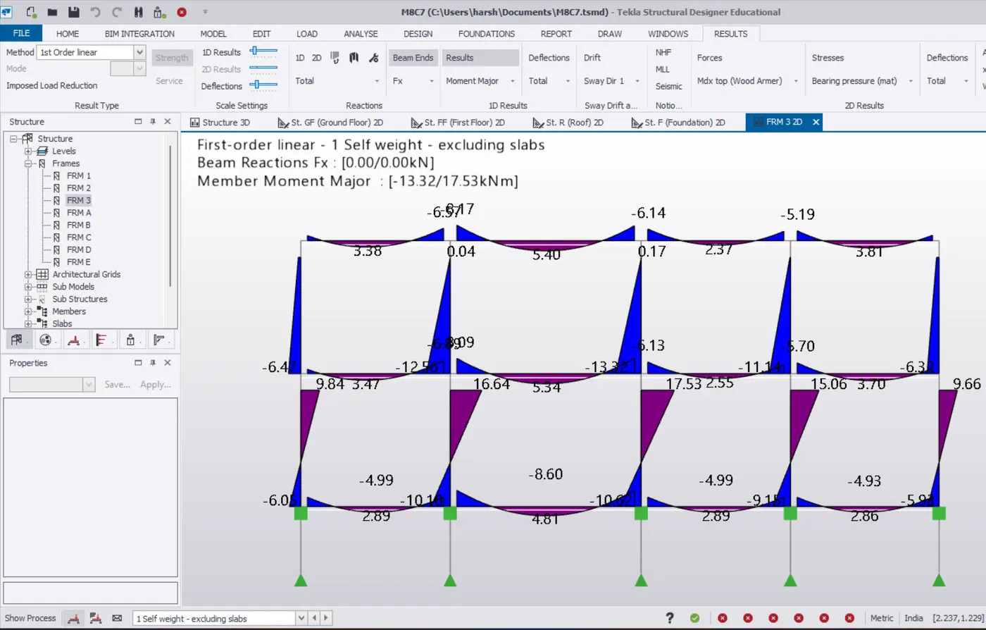
From the above,we can find that all the beams are having the same BMD and nearby values.As the beams are only subjected to their selfweight in this case,they have the same diagram and almost same values.All the beams are subjected to the negative moments at their ends as all the beams have fixed ends.And the mid portion has positive moment due to sagging due to self weight.
The upper columns do have the similar BMD as the load action is similar on all the columns.Where all the upper columns are subjected to the negative moments.In the similar manner,all the bottom columns do have the similar BMD but they have positive moments at the top which is resulted to counteract the negative moments of the beam ends.