To Generate seismic loading based on IS code and to run the analysis using TSD
Questions:-
- Generate seismic loading based IS codal provisions and zone II. Any other data you can assume and input accordingly.
- Run the analysis. Summarize your understanding of the analysis results.
Ans=
AIM:- To explain the answer for each and every question from 1 to 4.
INTRODUCTION:- In this section of question 1 and 2, I used Tekla structural designer software to answer these question. Besides this, I have used some reference from recorded video session of skill-lync. Loads cases and load combinations are generated, assigned for the structure using tekla and validation of those loads is an important part of Tekla Structural Designer as it ensures a valid model for the analysis and design routines.
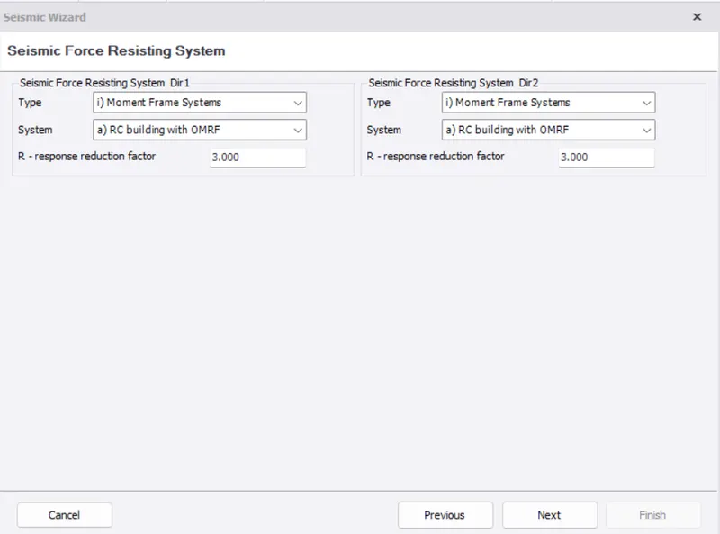
Seismic loads are generated according to IS 1893 codal provisions. Moment frame systems is taken for RC building with OMRF. It is an assembly of beams and columns that resist induced and externally applied forces primarily by flexure.
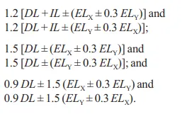
Design for horizontal earthquake load generated (IS 1893) as
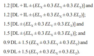
Design for vertical earthquake load (IS 1893) as
PROCEDURE:- Here first I will mention question one by one then answer then in the same manner.
Question- 1. Generate seismic loading based IS codal provisions and zone II. Any other data you can assume and input accordingly.
Ans=
- Open the model in tekla software.
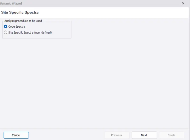
- Select seismic wizard under seismic loads
- Select code spectra and click on next
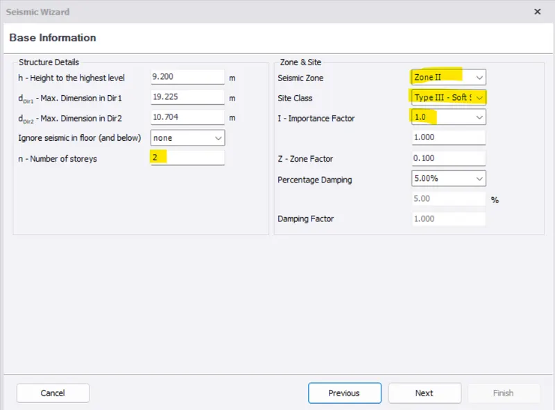
- Check the dimensions of the building and other details
- Zone is set as Zone II, site class a TypeIII soft, Importance factor as 1.0
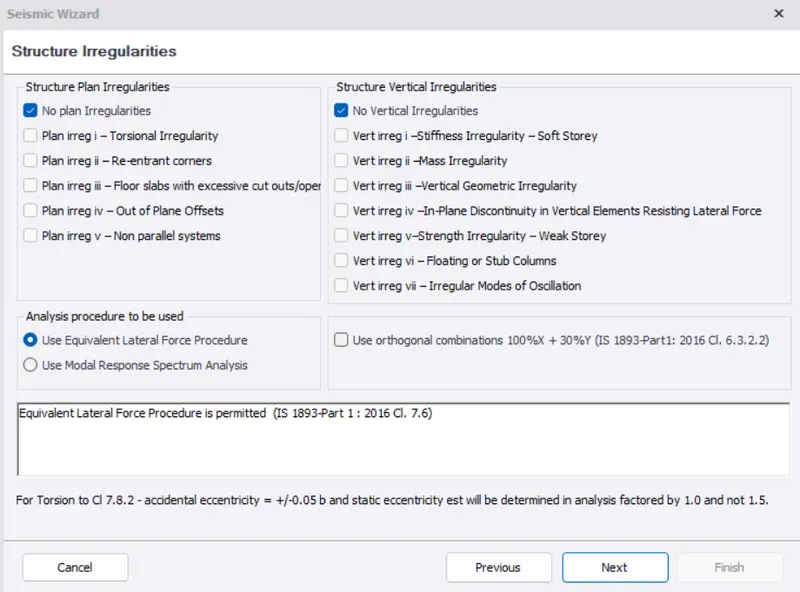
- Set structure irregularities and use equivalent lateral force procedure
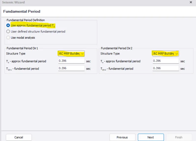
- Use Approximate fundamental time period
- Use 'Moment frame systems' for RC building with OMRF in Seismic force resisting system
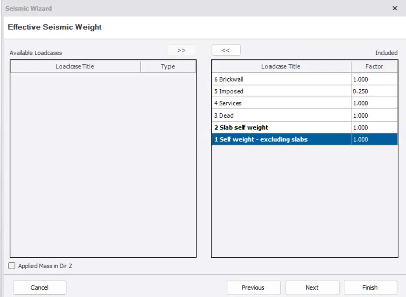
- Include all the loadcases : Self weight- excluding slabs, Slab self weight, Dead, Services and Imposed
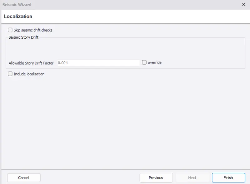
- Then take seismic storey drift
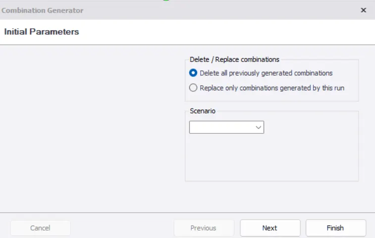
- Select 'Delete all previously generated combinations in combination generator
- Select finish
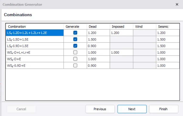
- Click Combinations on load tab to check the generation of seismic loads and then click generate
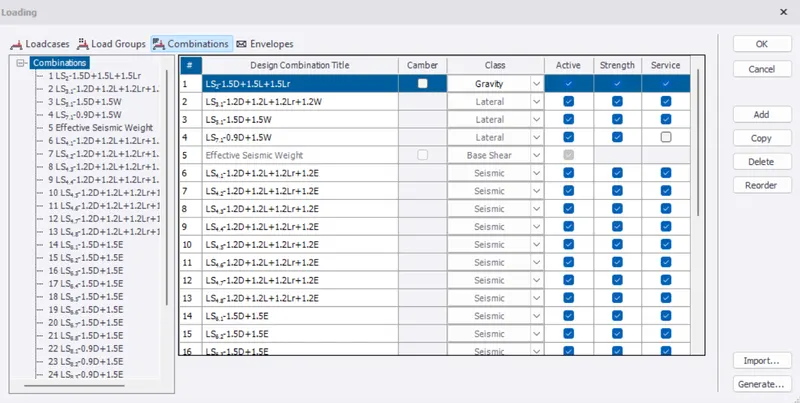
- Check and select next
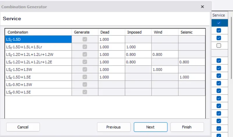
- Select finish
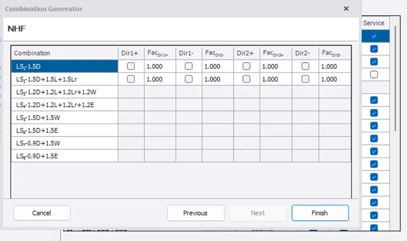
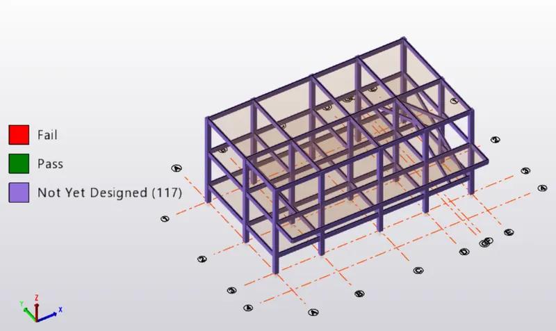
- Then we get Pass/Fail/ any warning, errors
- Select Review and click on "Auto design check"
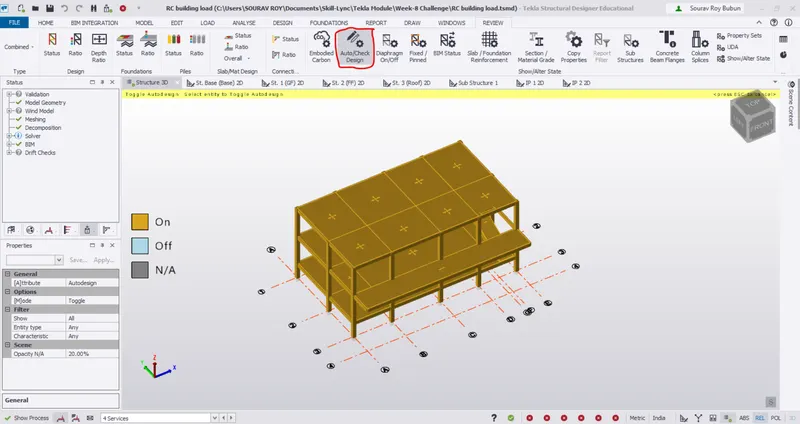
- Select "Show/Alter state"
- Now click on Entity type as "ANY" in properties and Remove from autodesign of members
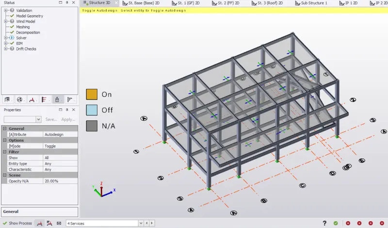
- Select Fixed/Pinned option
- Change members to Fixed
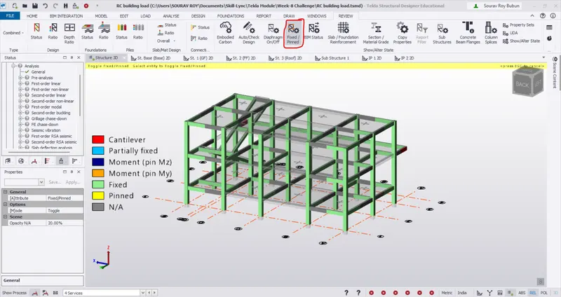
- Select Section/Material grade
- Change "Material grade" in attribute(proprties)
- Change mode as copy and material type as concrete
- Now If there is a need to change properties of beam, then select a beam which we want to copy to the other beam properties and select a beam that need to be changed
- Similary check and change column properties if necessary
RESULTS:-
Seismic parameters successfully applied in the model.
Question- 2. Run the analysis. Summarize your understanding of the analysis results.
Ans=
Analysis method is taken as Equivalent static method. Equivalent static is a simplification method to design earthquake loads that must be calculated in the structural design. This method is practical and easy to apply, but only appropriate for low structures with high rigidity.
The static analysis is based on several assumptions are:
(i) The structure assumed to be rigid,
(ii) The fixed bond between the structure and foundation is assumed perfect,
(iii) Every section of structure experience the same accelerations during ground motion,
(iv) Effect of an earthquake is assumed as a horizontal force on certain loading point
(v) The base shear force is approximately determined as the total of horizontal force on the structure
- Go to analyse tab and click on 1st order linear analysis
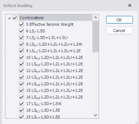
- Click ok and select "RESULTS"
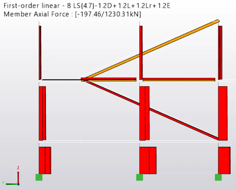
- Select "Axial force" in the results tab to get diagrams under axial loads and check under various combinations
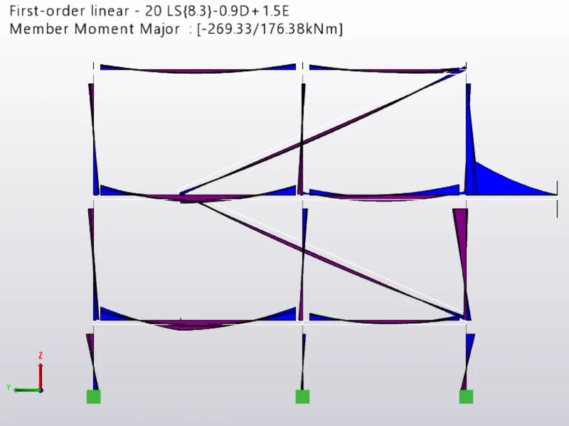
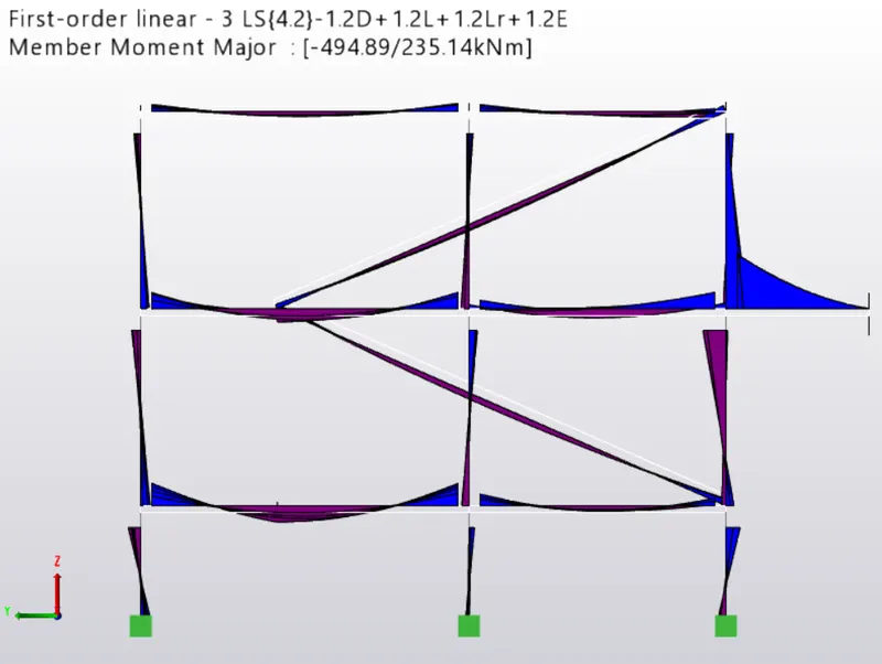
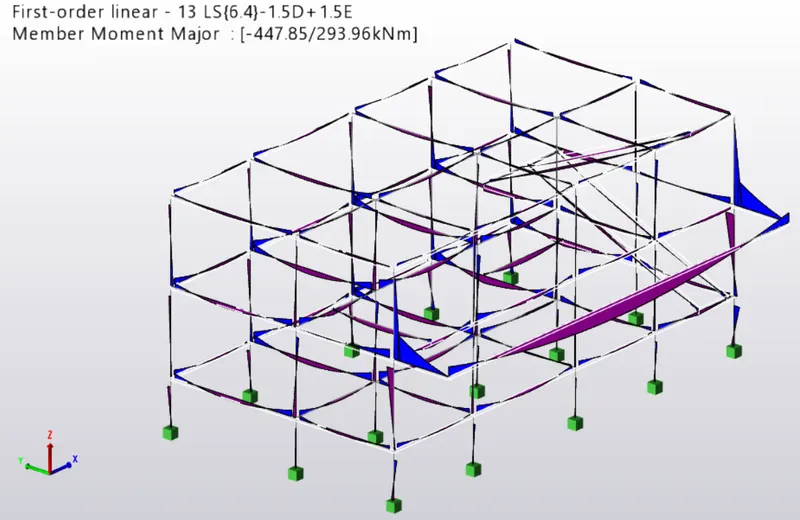
- Select "Moment major" in the results tab to get diagrams under moment and check under various combinations
- Select "Shear major" in the results tab to get diagrams under moment and check under various combinations
- Select "Deflections" in the results tab to get diagrams under moment and check under various combinations
RESULTS :
Axial load is more at the bottom (Direction 1)
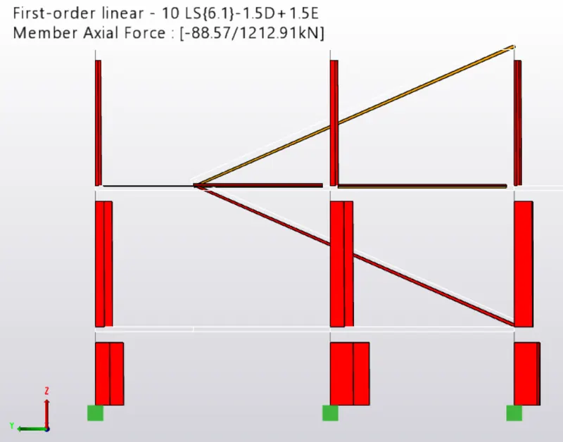
Axial load is more at the bottom (Direction 2)
Moment diagram is also as per lateral loading
Shear major:-
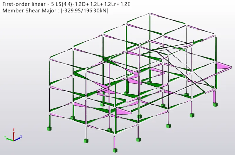
Seismic loading diagrams
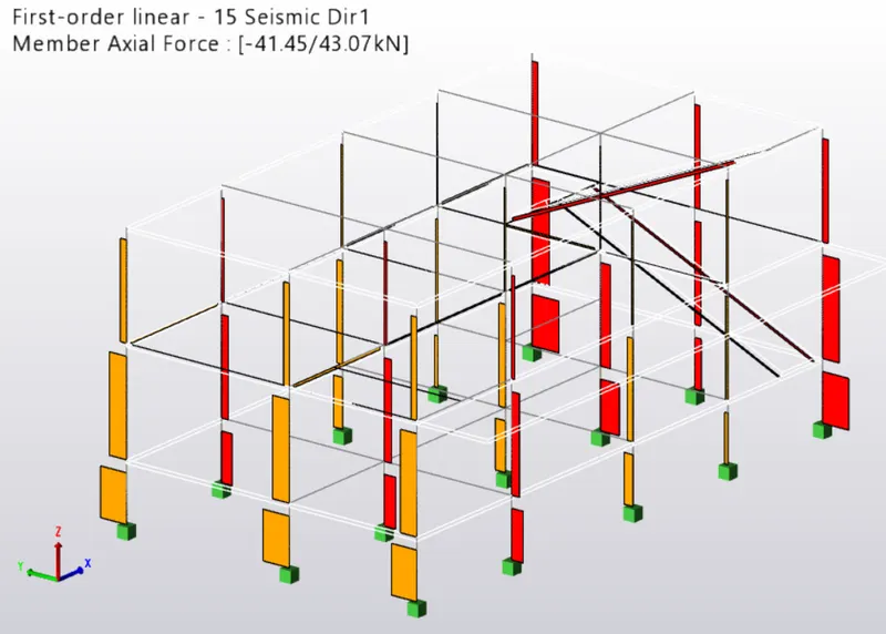
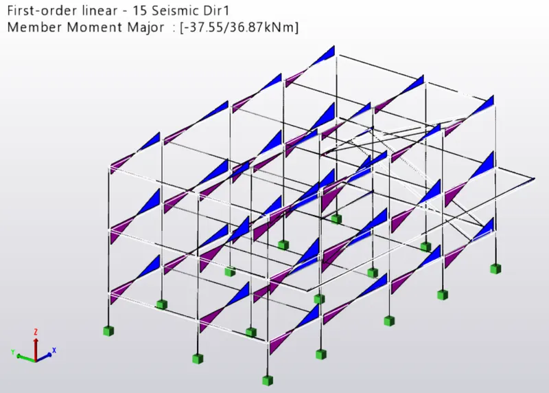
Deflections

Conclusion:-
Seismic load is successfully applied to the model and analysis has been accomplished successfully. Also, bending moment, shear force, axial forces and deflection results are displayed successfully. I have attached Tekla structural designer model in this challenge.