To calculate wind load for industrial steel structures and to apply it by using TSD
Questions:-
- Generate manual wind loading in the design report based IS code as per the following input
- Basic wind speed = 39m/s
- Terrain category 2
- Based on the above calculation apply the loadings on the model.
- On a separate model generate wind loading using wind wizard.
AIM:- To Generate manual wind loading in the design report based IS code and apply calculated wind load. Then generate wind loading using wind wizard in Tekla.
INTRODUCTION:- In this section of question from 1 to 3, I used Tekla structural designer software to answer these question. Besides this, I have used some reference from recorded video session of skill-lync. I have
PROCEDURE:- Here first I will mention question one by one then answer then in the same manner.
Question- 1. Generate manual wind loading in the design report based IS code as per the following input
- Basic wind speed = 39m/s
- Terrain category 2
Ans=
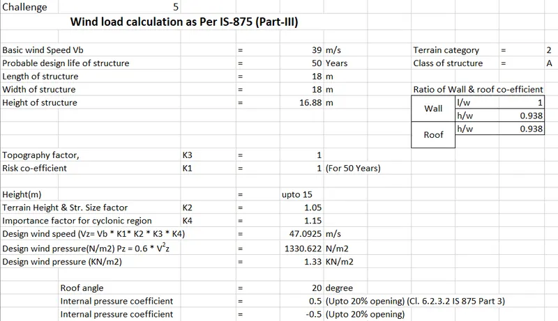
Terrain category is given as 2
Vb = Basic wind speed which is given as 39m/s
Normally basic wind speed is selected from appendix A of code book IS 875 (Part-III) which is given based on wind speed in various cities
Design wind speed Vz= Vb*K1*K2*K3*K4
Where Vz depends on risk level, terrain roughness, height, size of structure, local topography
K1 = Probability factor
It is taken from table 1 of IS 875 III
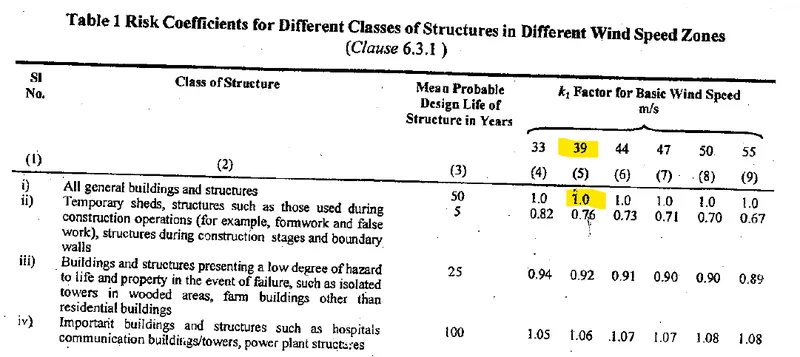
Life of structure is taken as 50 yrs and wind speed is given as 39m/s. Based on this K1 =1
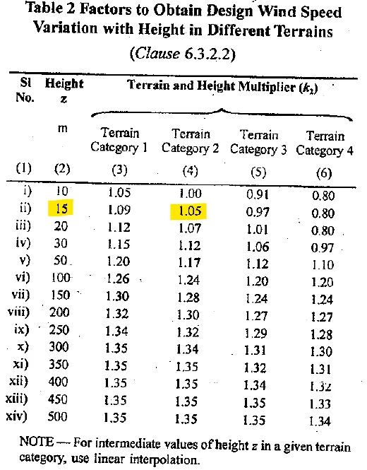
K2 = Terrain, height, structure factor which is taken from table 2 = 1.05
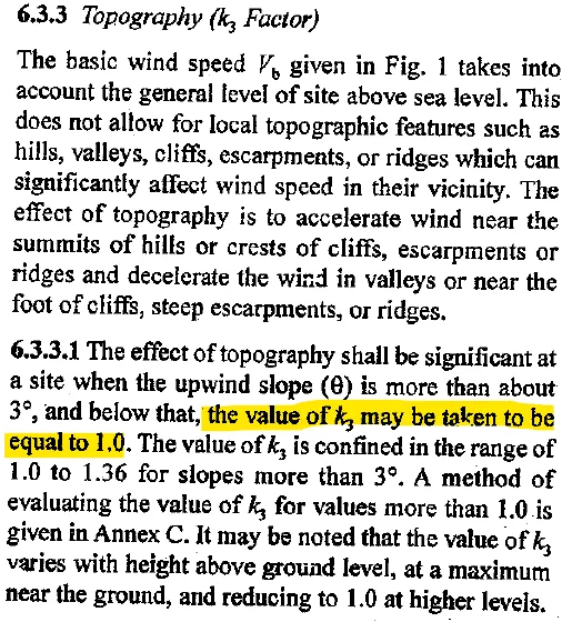
K3 = Topography factor which is taken as 1 (θ">θθ<3 = 1 and θ">θθ>3 = 1 to 1.36)
K4 = Importane factor for cyclonic region K4 is taken as 1.15
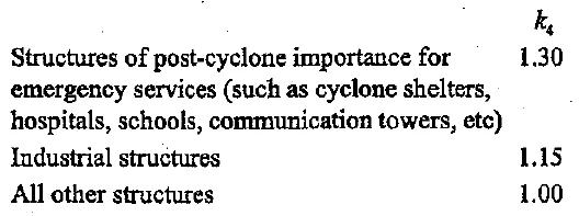
Where K4 = 1.3 Structure for post cyclonic importance
= 1.15 Industrial structure
= 1 All other structure
PROCEDURE:-
- Wind speed = 39m/s
- Life period = 50yrs
- Terrain category = 2
- Design wind speed Vz = Vb x K1 x K2 x K3 x K4 = 39 x 1 x 1.05 x 1 x 1.15 = 47.09m/s
- Design wind pressure = Pz = 0.6 x Vz^2">^2 = 1330N/m2 = 1.33KN/m2
- Length = 18m, Width = 18m, Height = 16.88m
- L/W = 1 and H/W = 0.937
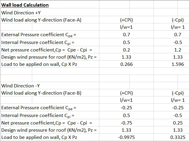
- External pressure coefficients for wall is taken from table 5 IS 875 III (H/W=0.937)

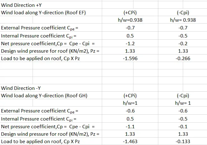
- Roof angle is calculated and based on roof angle external pressure for roof is calculated based on table of IS 875 III
- We have calculated roof angle as 20 degree.

RESULTS
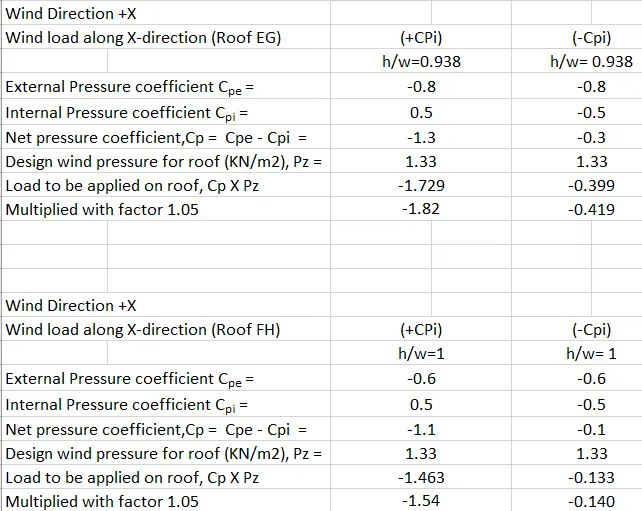
Question- 2. Based on the above calculation apply the loadings on the model.
Ans=
Step-1
Application of wind load on Model
First Open the last week file of Tekla
Then Click on Load cases option
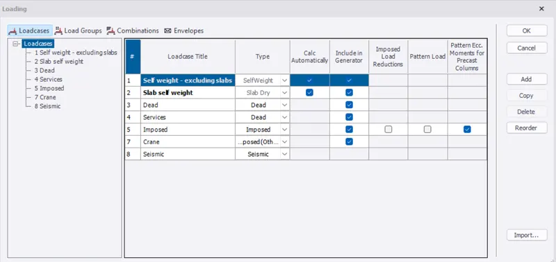
As we are manually applying the wind loads create the new wind load cases by clicking on add option and rename it
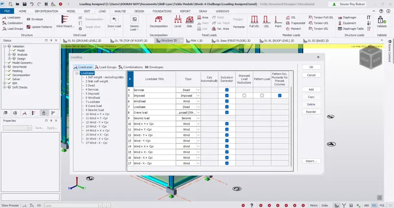
Step-2
For wall section
Apply the wind load for 1st Case i.e Wind + Y and +Cpi
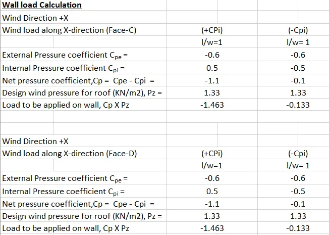
The faces A, B, C and D corresponds to frame 1,4, A and D in model .
The negative value of load shows that load is acting away from building and positive value shows it acts towards the building.
A ) Open Frame 1 and apply load 0.266 Kn/m^2
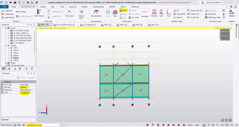
Second case Wind +Y -Cpi
Open Frame 1 and apply load 1.596 Kn/m^2
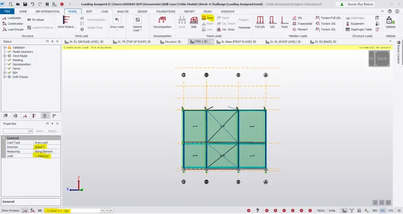
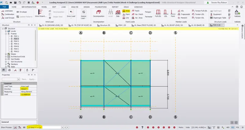
Third case Wind -Y +Cpi
Open Frame 4 and apply load -0.9975 Kn/m^2
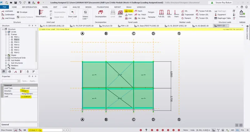
Fourth case Wind -Y -Cpi
Open Frame 4 and apply load 0.3325 Kn/m^2
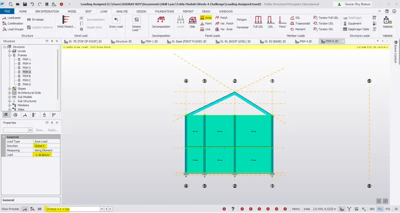
Fifth case Wind +X +Cpi
Open Frame A and apply load -1.463 Kn/m^2
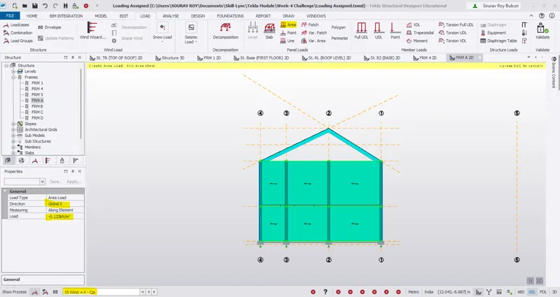
Sixth case Wind +X -Cpi
Open Frame A and apply load -0.133 Kn/m^2
Seventh case Wind -X +Cpi
Open Frame D and apply load -1.463 Kn/m^2
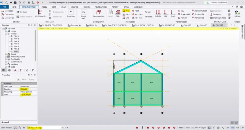
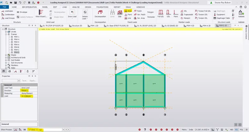
Eighth case Wind -X -Cpi
Open Frame D and apply load -0.133 Kn/m^2
Step-3
For Roof section
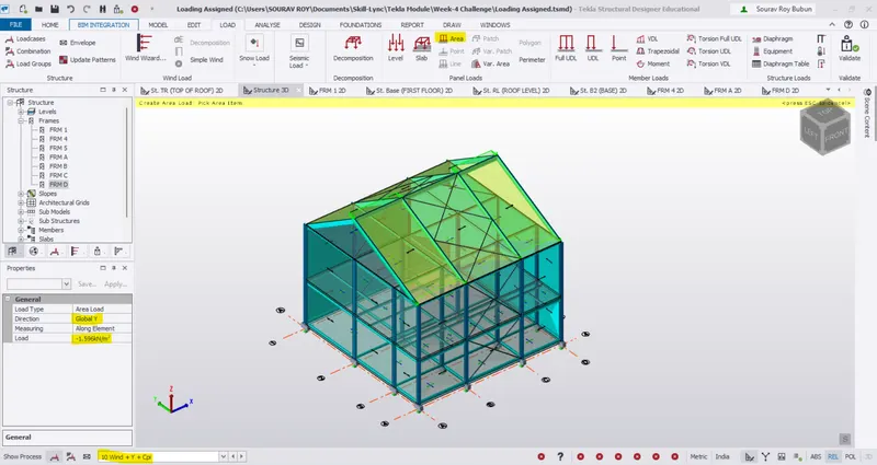
First We will Consider EF side
For, Wind + Y + Cpi
apply load -1.596 Kn/m^2
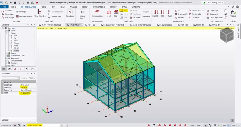
For, Wind + Y - Cpi
apply load -0.266 Kn/m^2
Now We will Consider GH side
For, Wind - Y + Cpi
apply load -1.463 Kn/m^2
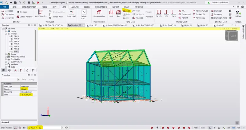
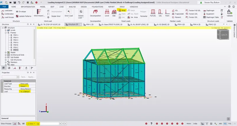
For, Wind - Y - Cpi
Apply load -0.133 Kn/m^2
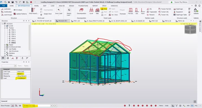
We will consider EG side
For, Wind + X + Cpi
Apply load -1.82 Kn/m^2
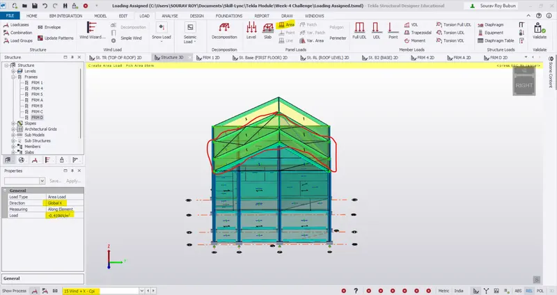
For, Wind + X - Cpi
Apply load -0.419 Kn/m^2
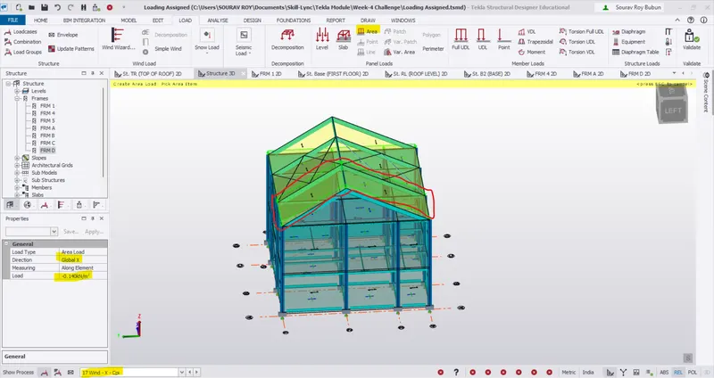
We will consider FH side
For, Wind - X + Cpi
Apply load -1.54 Kn/m^2
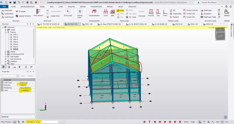
For, Wind - X - Cpi
Apply load -0.140 Kn/m^2
Question- 3. On a separate model generate wind loading using wind wizard.
Ans=
- Delete previous wind loads
- Now click wind wizard in load tab
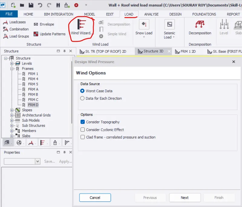
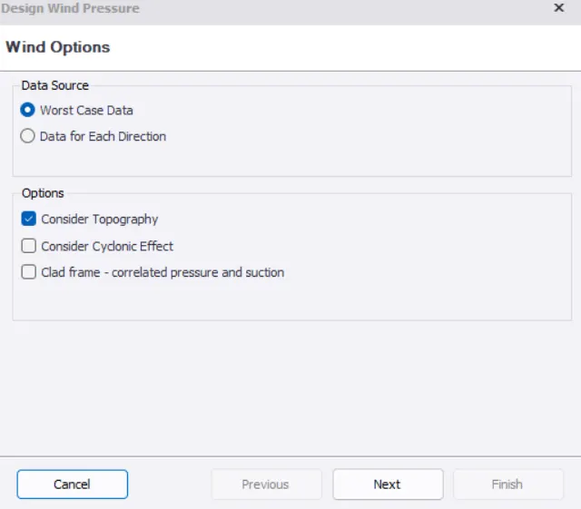
- Click on worst case data and click next
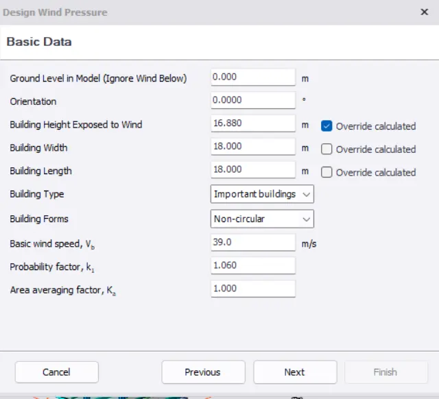
- Set height as 16.88m, Type industrial and wind speed 39m/s and click next
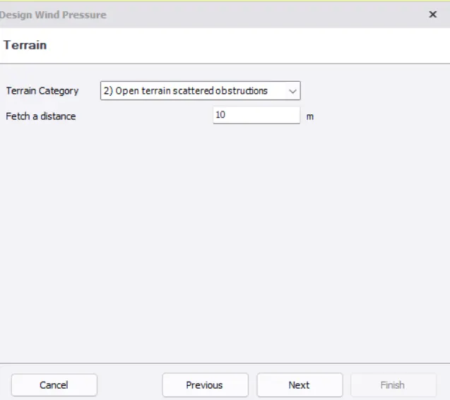
- Set terrain category as open terrain scattered obstruction, fetch a distance as 10m and click next
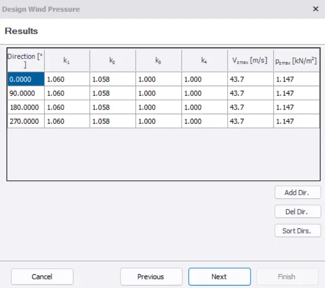
- Click next for results and direction
- Click on load cases and add wind loads as shown below
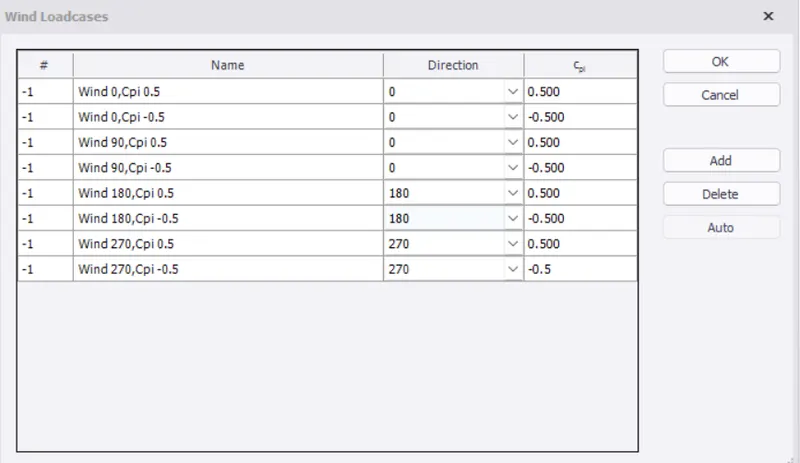
Wind loads are generated through wind wizard
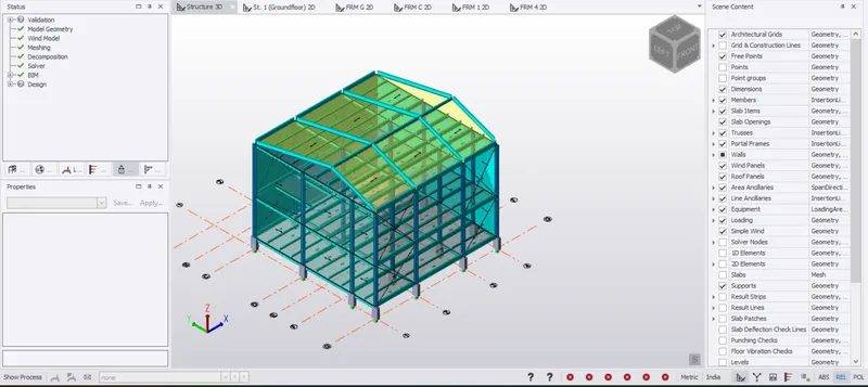
Results -
i) Wind loads and roof loads is calculated based on IS 875 Part III.
ii) The wind load and roof load applied to the steel structure.
iii) A separate model is created and wind load is calculated using the Tekla software’s wind wizard.
Conclusion:-
All the three tasks has been accomplished successfully and Excel file of Wind load coefficient calculaion and Tekla file for Roof panel and wall panel load assignment.