To calculate wind load for industrial steel structures and to apply it by using TSD
1.
We have,
Vb= 39 m/s
k1,k3,k4 =1
k2=1.03
Vz= Vb* k1 k2 k3 k4 = 40.17m/s
Pz = 0.6 Vz^2 = 968.2 N/m^2 = 0.968 KN/m^2
Height of the building,H = 13m
Maximum horizontal distance, L= 18m
Maximum Vertical distance,W= 18 m
Therefore,
Loads on the wall
The load to be applied on the wall along the face A externally
- H=12m
- Cpe=0.7
- Cpi = 0.6
- Cp = 0.1
- Pz= 0.968
- Load = 0.0968KN
The load to be applied on the wall along the face A internally
- H=12m
- Cpe=0.7
- Cpi = -0.6
- Cp = 1.3
- Pz= 0.968
- Load = 1.258 KN
The load to be applied on the wall along the face B externally
- H=12m
- Cpe=-0.25
- Cpi = 0.6
- Cp = -0.85
- Pz= 0.968
- Load =-0.822 KN
The load to be applied on the wall along the face B internally
- H=12m
- Cpe=-0.25
- Cpi = -0.6
- Cp = 0.35
- Pz= 0.968
- Load = 0.338KN
The load to be applied on the wall along the face C externally
- H=12m
- Cpe=-0.6
- Cpi = 0.7
- Cp = -1.3
- Pz= 0.968
- Load = -1.258 KN
The load to be applied on the wall along the face C internally
- H=12m
- Cpe=-0.6
- Cpi = -0.7
- Cp = 0.1
- Pz= 0.968
- Load = 0.0968KN
The load to be applied on the wall along the face D externally
- H=12m
- Cpe=-0.6
- Cpi = 0.25
- Cp = -0.85
- Pz= 0.968
- Load = -0.822KN
The load to be applied on the wall along the face D internally
- H=12m
- Cpe=-0.6
- Cpi = -0.25
- Cp = -0.35
- Pz= 0.968
- Load =-0.338KN
Loads on the roof
The load to be applied on the roof along EF internally
- H=12m
- Cpe=-0.7
- Cpi = -0.5
- Cp = -0.2
- Pz= 0.968
- Load =-0.1936KN
The load to be applied on the roof along EF externally
- H=12m
- Cpe=-0.7
- Cpi = 0.5
- Cp = -1.2
- Pz= 0.968
- Load =-1.16KN
The load to be applied on the roof along GH internally
- H=12m
- Cpe=-0.5
- Cpi = 0.5
- Cp = -1
- Pz= 0.968
- Load =-0.968KN
The load to be applied on the roof along GH externally
- H=12m
- Cpe=-0.5
- Cpi = 0.5
- Cp = -1
- Pz= 0.968
- Load =-0.968KN
2.
Aim: To apply the loadings as per calculation on the model
Procedure:
- Open the saved Tekla model
- Now insert the load cases
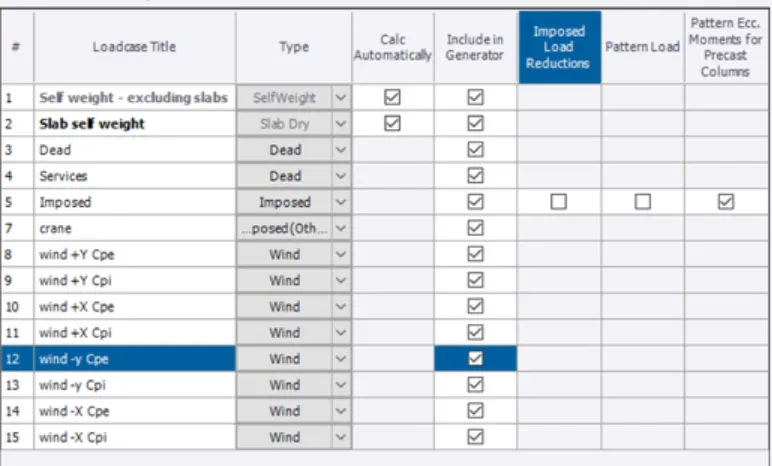
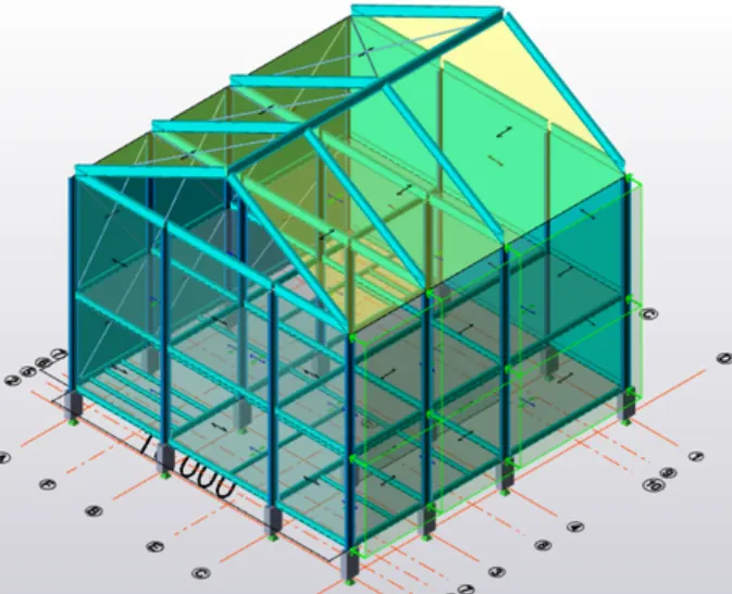
- Now go to Load and select area load, global axis and enter the value of loads corresponding the face.
- Example, now we have applied, load value of -0.0968KN along face A.
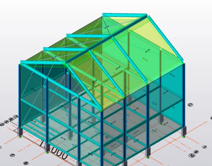
- Similarily, we have to select area load and global axis and enter the value of face B. Apply the values of internal pressure coefficients to both the faces, (1.258KN and 0.338 KN)
- Load value of -1.258 is applied at face C as external pressure coefficient
- Load value of -0.822 is applied at Face D as external pressure coefficient
- Similarily we apply the loads due to internal pressure coefficients at corresponding faces
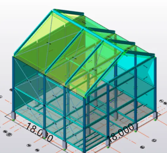
- Now to apply the loads on the roof, select load combinations, select load and enter the values on face EF as 1.16KN and apply load of 0.968KN on face GH.
- Now apply the loads due to internal pressure
3.
Aim: Using Wind wizard, to generate wind loading on a separete model
Procedure:
- Apply Wind wizard from the Ribbon pallet
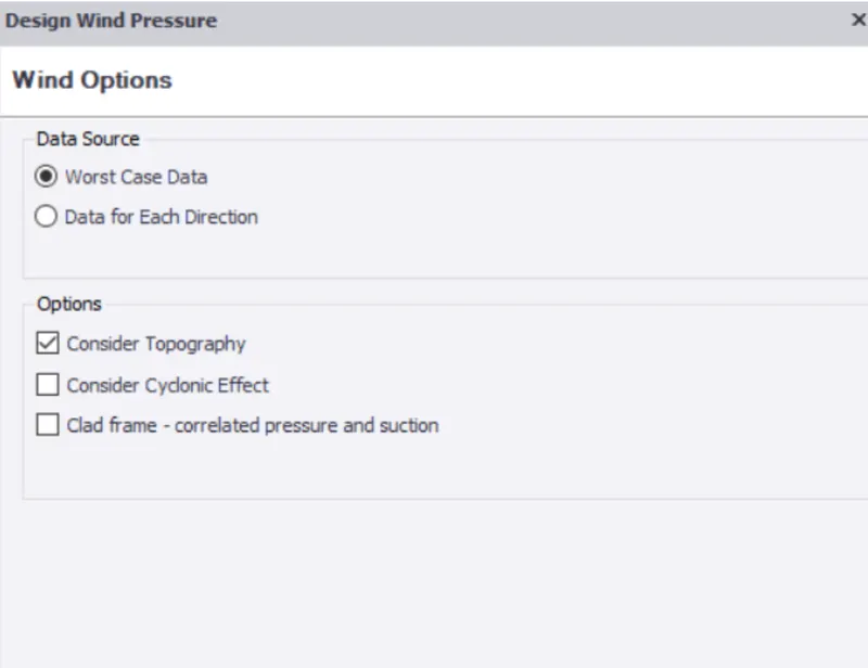
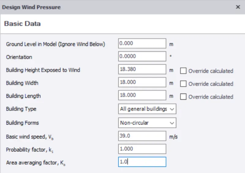
- Now the Wind design pressure
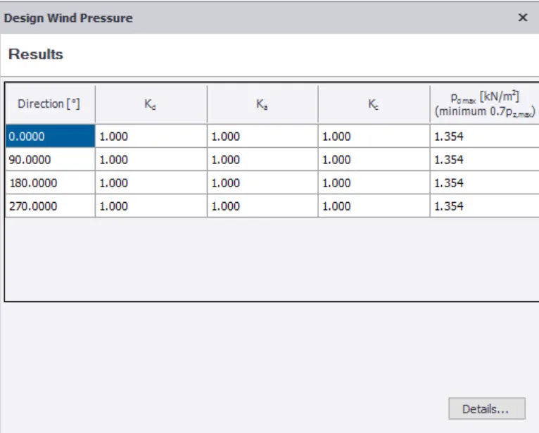
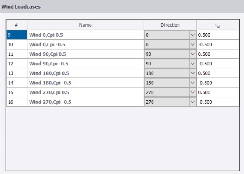
- Now we have to provide the Wind Load Cases
- Now we need to analyse the model the model and select the first order linear analysis
Result: Results can be obtained after analysis like moment major, moment minor, shear etc.