Drafting of various geometries using Chamfer, Fillet tool in AutoCad
`Aim: Drafting of various given geometries using Chamfer, Fillet tool in AutoCad
Introduction: AutoCad offers various functions and tools to improve the designing thus enhancing the easiness, some of them are fillet, chamfer, rotate, mirror, etc.
Initial procedure:
- Start by typing QNEW in the command box
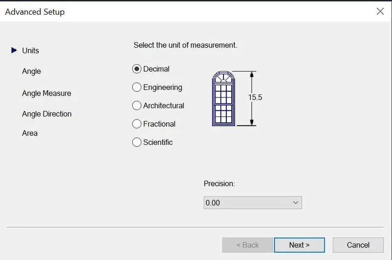
- Advanced Setup > Set the Units, Angle, Angle measure, Angle direction and area
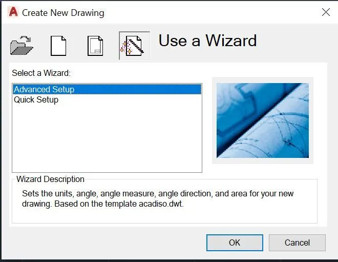
- After settings provide the lower limit and upper limit.
- Now we can start the sketching.
Drawing No:1
Procedure:
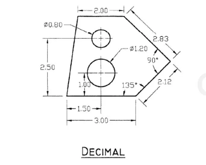
- In Advanced Setup, select Decimal and set precision to 0.000
- In the command box, type Polyline and specify the first start point 1,1
- Specify the next point @3<0
- Specify the next point @2.12<45
- Specify the next point @2.83<135
- Specify the next point @2<180
- Now close
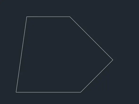
- Now type OBJECTSNAP in the command box, and click on for END-POINT and MID-POINT.
- Select the Mid-point of line with 3m length, i.e; the base line here.
- Now draw a line using Line @1<90
- Use the option centre-diamter in circle, and provide the last point as the center and diameter as 1.20.
- Now delete the line joining the points, mid of the 3m line and @1<90.
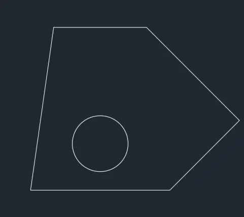
- Now select the mid point of the base line with 3 m and draw a line making the mid point as the start point, to the next point as @2.50<90.
- Use the option centre-diamter in circle, and provide the last point as the center and diameter as 0.80.
- Now delete the line joining the points, mid of the 3m line and @2.50<90.
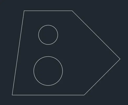
Result:
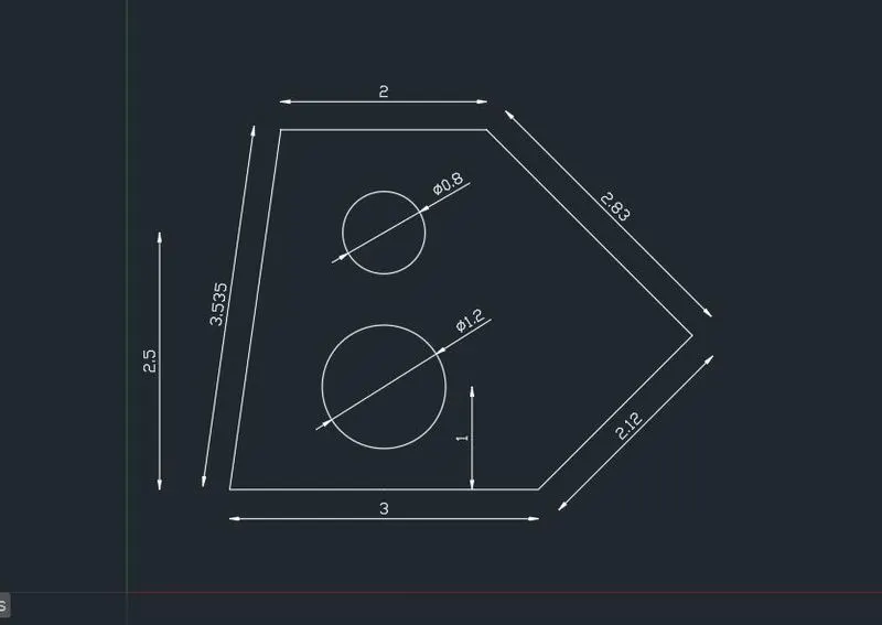
Drawing No:2
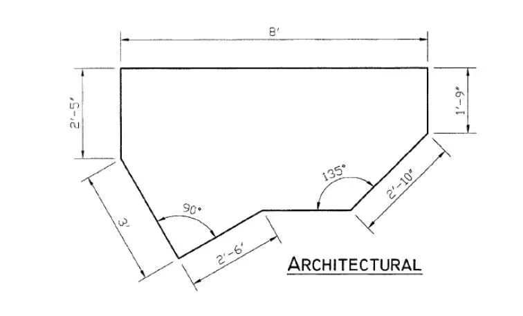
Procedure:
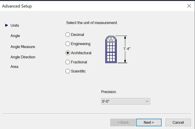
- In Advanced setup select Architectural and set the precision to 0'-0"
- Now Select the Polar tracking as 45,90,135,180
- Using Line command, select any random point as the first point.
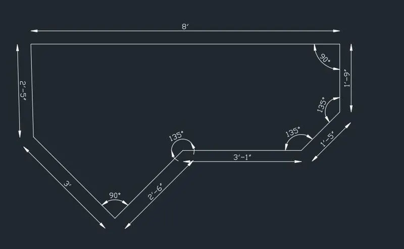
- Point the cursor to the left with an angle of 135, and type the distance as 3'
- Point the cursor to the right with an angle of 45, and type the distance as 2'-6"
- Point the cursor to the right with an angle of 0, and type the distance as 3'-1"
- Point the cursor to the right with an angle of 45, and type the distance as 1'-5".
- Point the cursor to the right with an angle of 90, and type the distance as 1'-9"
- Point the cursor to the right with an angle of 180, and type the distance as 8'.
- Now close .
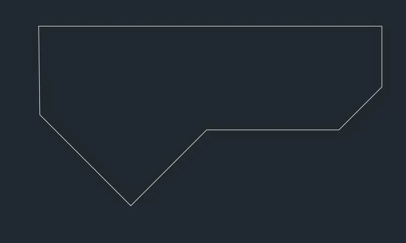
Result:
Drawing No:3
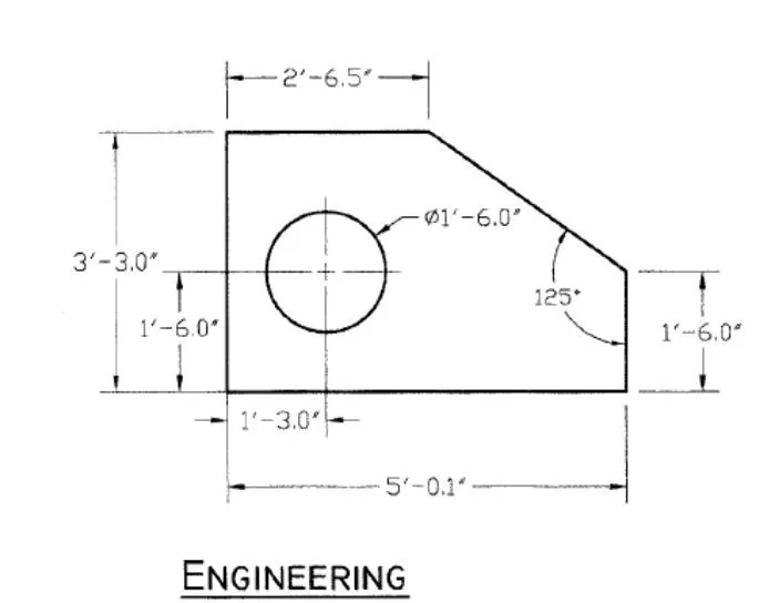
Procedure:
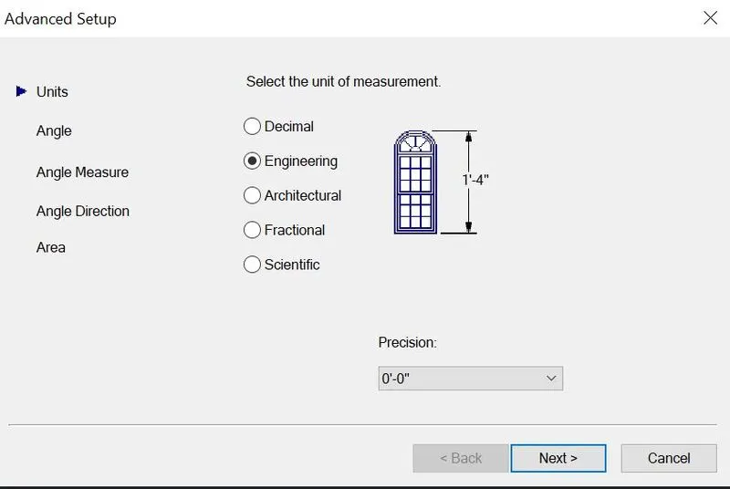
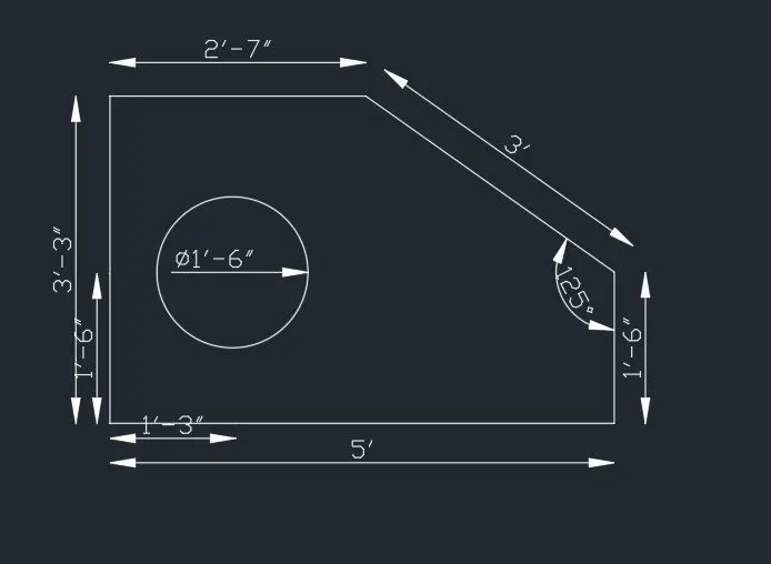
- In Advanced setup select Engineering and set the precision to 0'-0"
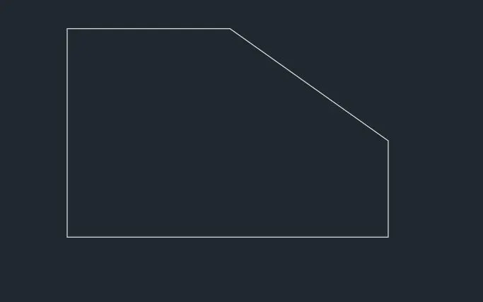
- Using Line command, draw a line with length 5'0.10" at 0 angle
- Draw a line 3'3" at 90 angle
- At angle 0, draw a line 2'6.50" and close
- Now Using Line command, sketch a line 1'6" at 90 angle.
- Now close it to make a closed figure.
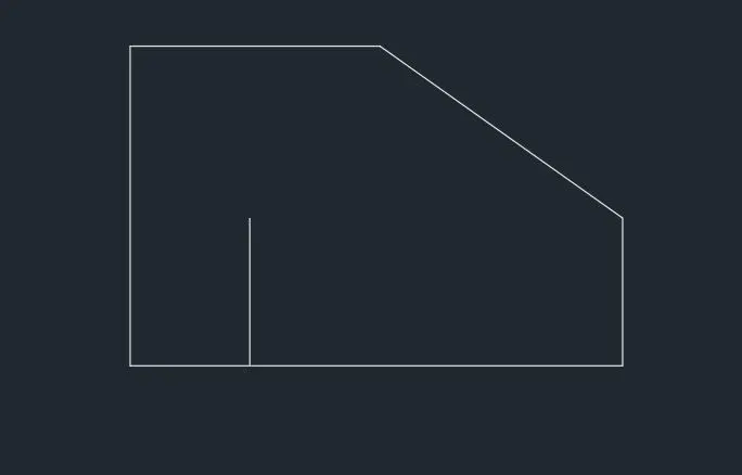
- Now draw a line using Line command at 1'3" in the base line and draw a line 90 angle with length 1'6".
- Use the option centre-diamter in circle, and provide the last point as the center and diameter as 1'6".
- Now delete the perpendicular line.
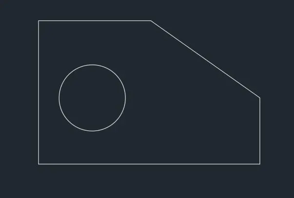
Result:
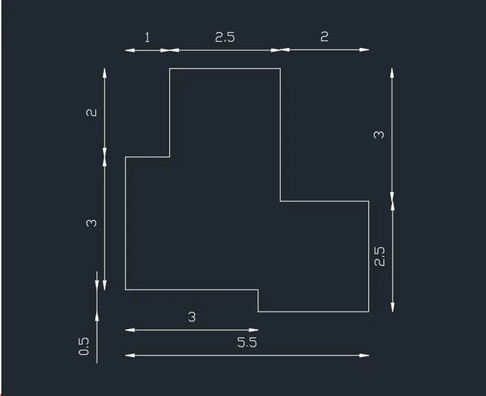
Drawing No:4
Procedure:
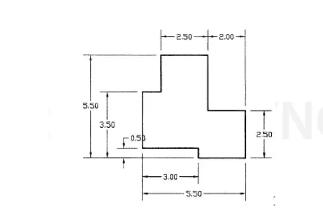
- In Advanced Setup, select Decimal and set precision to 0.0
- Start sketching by selecting PolyLine in the command bar
- Specify the starting point as any random point.
- Switch On the ortho
- Start sketching by inputing the distance 3.0
- Next point length as 0.5
- Next point length as 2.5
- Next point length as 2.5
- Next point length as 2
- Next point length as 3
- Next point length as 2.5
- Next point length as 2
- Now press Esc
- Start from the first initial point to length 3
- Now join the two lines.
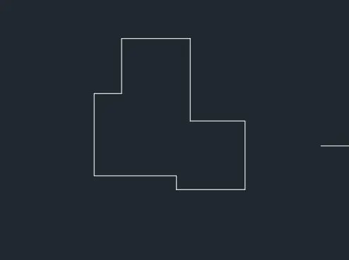
Result:
Drawing No:5
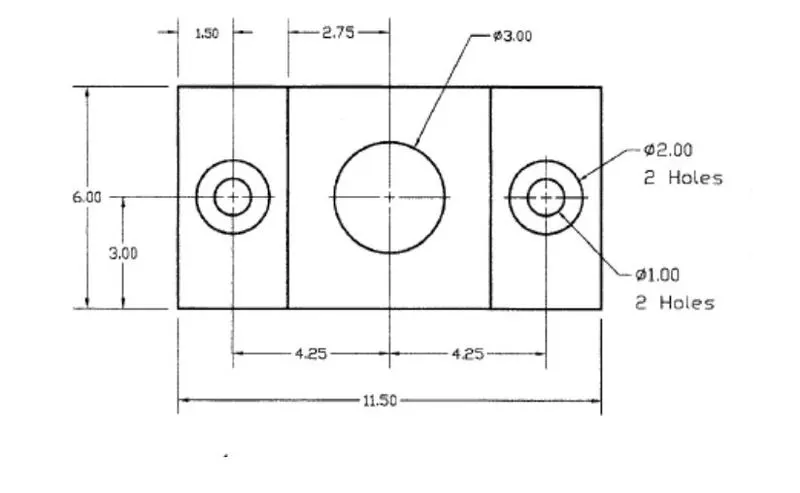
Procedure:
- In Advanced Setup, select Decimal and set precision to 0.0
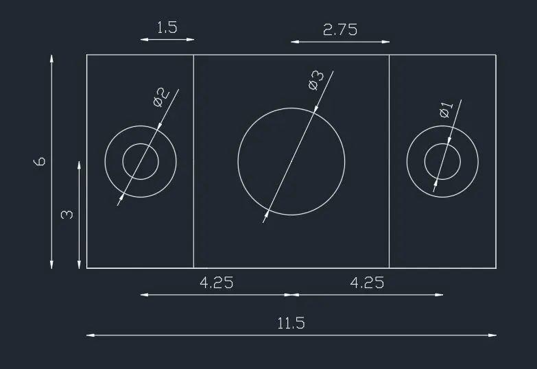
- Using Rectaangle from the command bar, sketch a rectangle, with starting point 0,0 and corner point 11.5,6.
- Draw a line at both the extreme side of the rectangle and make an offset of distance 3 from each.
- Draw lines in each divided rectangles
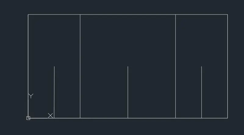
- Turn on OSnap and find the mid of each rectangle and draw 3 lines of distance 3.
- For outer circles, Use the option centre-diamter in circle, and provide the end point as the center and diameter as 2 for the end circles 3 for middle circle.
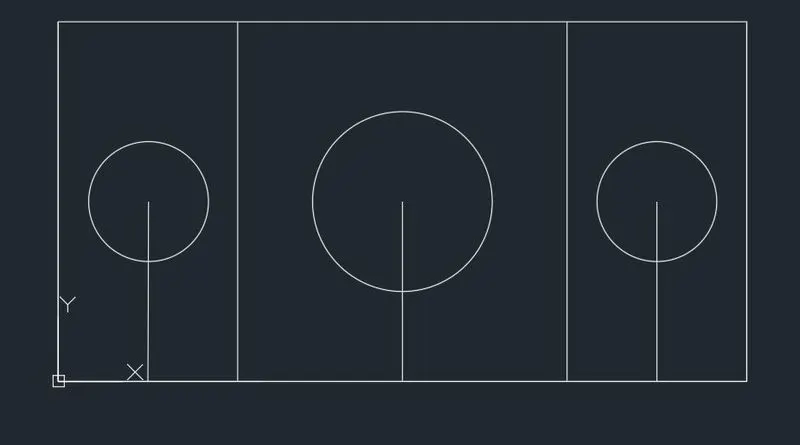
- For inner circles, Use the option centre-diamter in circle, and provide the end point as the center and diameter as 1 for the end circles
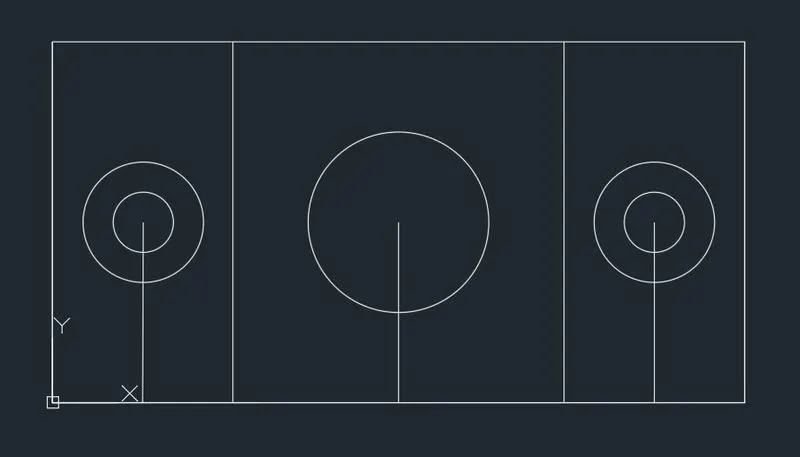
- Now erase the previously drawn 3 perpendicular lines.
Result:
Drawing No:6
Procedure:
- In Advanced Setup, select Decimal and set precision to 0.0
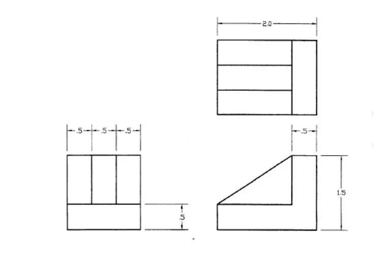
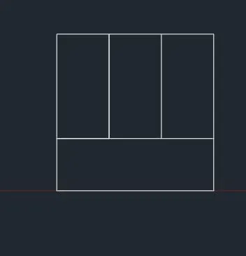
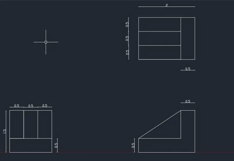
- Using rectangular tool, sketch rectangle with starting point as 0,0 and corner point,1.5,0.5
- Using Line tool, draw a line of 0.5 perpendicular to the last point.
- Using the Offset tool, create two offset of 0.5 distance each.
- Now joint the top using Line tool.
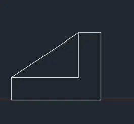
- Using the Line command, specify the first point.
- Now start stekching by giving the lengths
- Specifying the next point distance as 2.0
- Specifying the next point distance as 1.5
- Using offset, make an offset line at 0.5 distance from the vertical
- Specifying the next point distance as 0.5.
- Using offset tool, draw two offset lines of 0.5 each for the vertical.
- Now join the edges
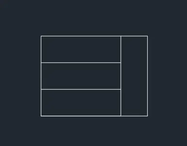
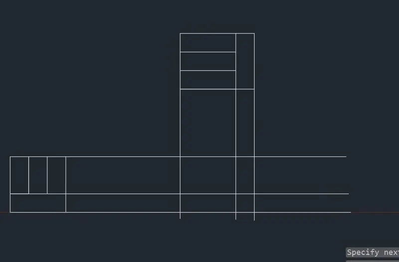
- Extend the two drawings.
- Join the intersection points using the Line command.
- Trim the unwanted lines with the help of Trim command.
Result:
Drawing No:7
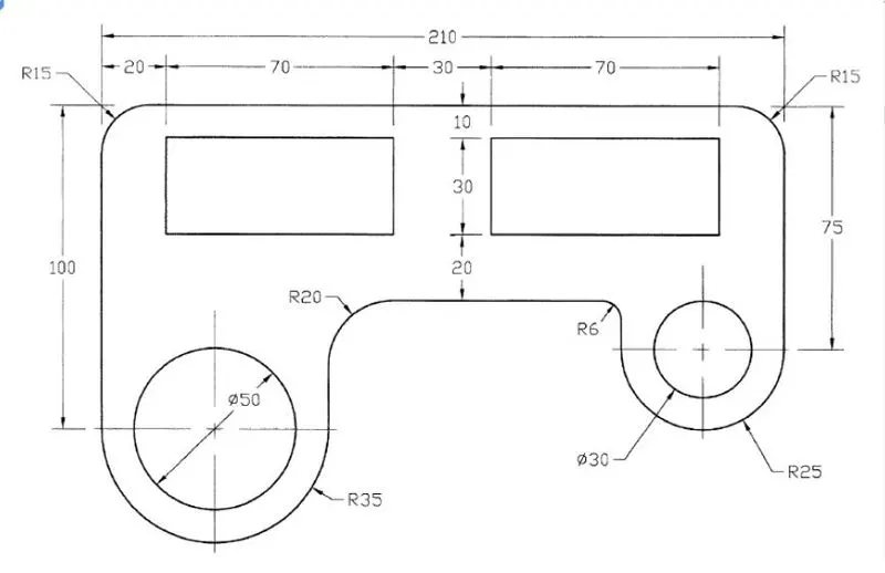
Procedure:
- In Advanced Setup, select Decimal and set precision to 0.0
- Using Line command, draw a line with a distance 100
- Next line with distance 210
- Next line with distance 75
- Using Fillet tool
- Give the fillet radius as 15
- And select the lines.
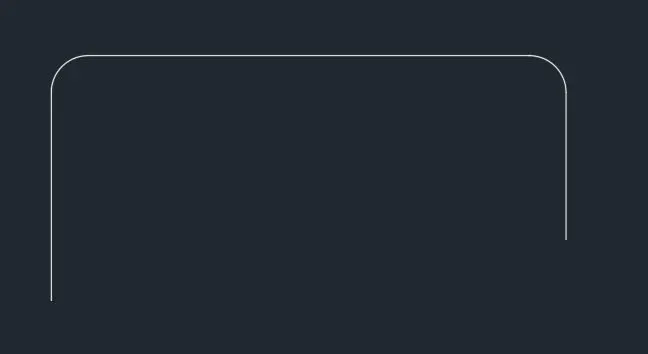
- From the end point of 100 measure line draw a horizontal line of 70
- Select centre-radius from circle menu
- Select the midpoint of the previous line and radius as 35.
- Select, centre-diameter, from the circle menu
- The centre is the centre of the previous circle and diameter is 50.
- From the end point of line 70, sketch a vertical of 40
- From the end point of 75 draw a horizontal line of 50
- Select centre-radius, from circle menu
- Centre is the mid point of the previous line and radius is 25
- Select centre-diameter, from the circle menu
- Centre is the centre of previous circle and diameter is 30.
- From the end point of the line 50, draw a vertical line of 15
- Complete the gap with Line command.
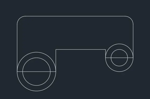
- In the command bar, type Fillet, giving radius as 20
- Select the lines
- Now again select fillet giving radius 6.
- Select the lines
- Now draw a rectangle of 70 ,30 at a distance 20,10 from the left top corner
- Using the offset , offset the rectangle at a distance of 30.
- Trim the unwanted lines.
Result:
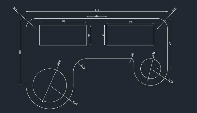
Drawing No:8
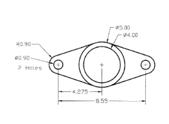
Procedure:
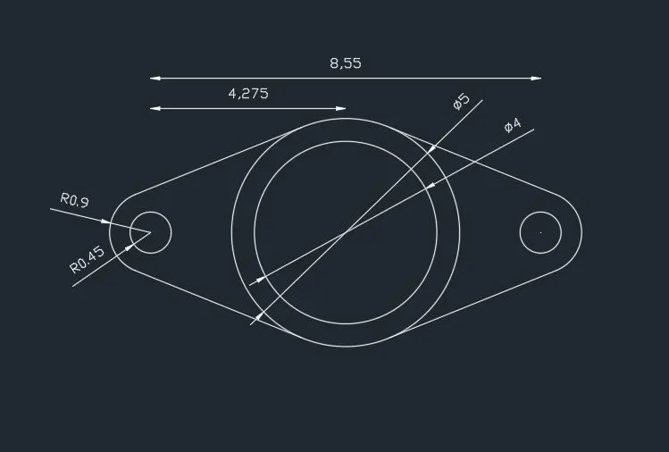
- Using the Line command, draw line of distance 8.550
- From Menu bar, select centre-diameter from circle. Centre is the end point of 8.550 and diameter is 0.9
- From Menu bar, select centre-radius from circle, taking the end point of 8.550 as centre and 0.90 as radius
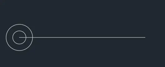
- Again from the Menu bar, select centre-diameter from circle. Centre is the end point of 8.550 and diameter is 0.9
- From Menu bar, select centre-radius from circle, taking the end point of 8.550 as centre and 0.90 as radius
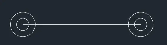
- Again from the Menu bar, select centre-diameter from circle. Centre is the mid point of 8.550 and diameter is 5
- From Menu bar, select centre-diameter from circle, taking the mid point of 8.550 as centre and 4 as diameter
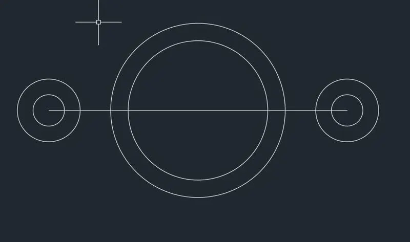
- Join the tangents of the outer circle using lines.
- Trim the unwanted lines
Result:
Drawing No:9
Procedure:
- From the advanced setup, select units type, Engineering precision to 0,0
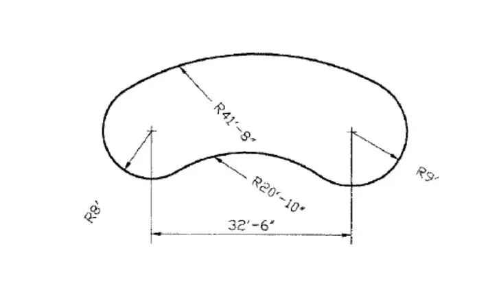
- Using Line command, sketch a line of 32'6"
- Using Centre-diameter from circle in the menu bar, construct a circle with centre as the end point of= 32'6" and diameter 8'
- From the Menu bar, select center-diameter from the cicle, and construct a circle with center as the end point of line 32'6" and diameter 9'
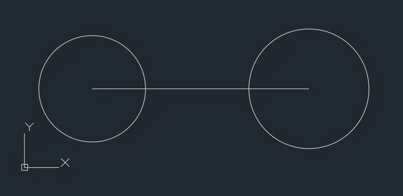
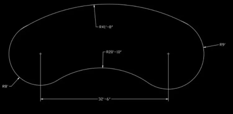
- From start, end and radius drawing, an arc of radius 41'8" on top and 20'10" on bottom
- Now trim the unwanted lines.
Result:
Drawing No:10
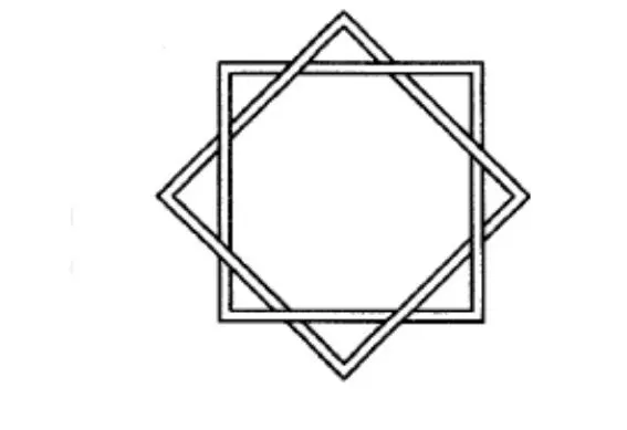
Procedure:
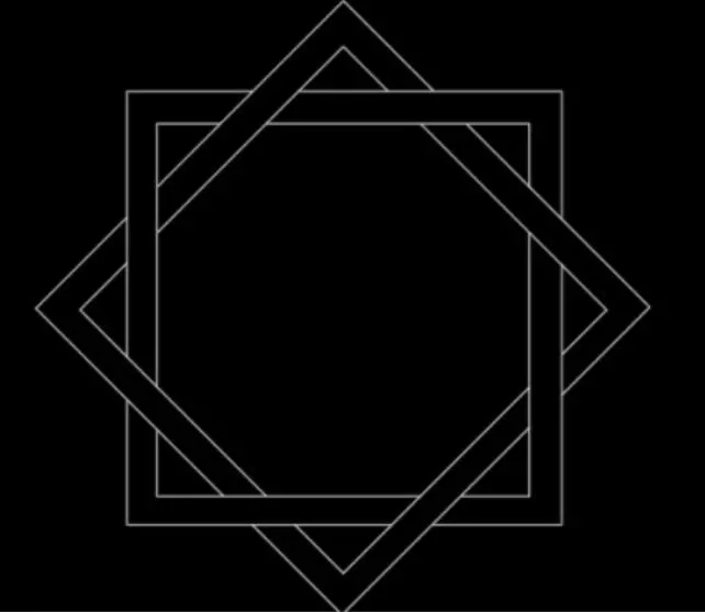
- Using Rectangular command, draw a rectangle of same length and same width of which, one is smaller size compared to the other.
- Using the Rotate command, rotate the drawn squares by 45 degree angle keeping the copy.
- Using Trim command, trim the crossing line according to the figure.
Result:
Drawing No:11
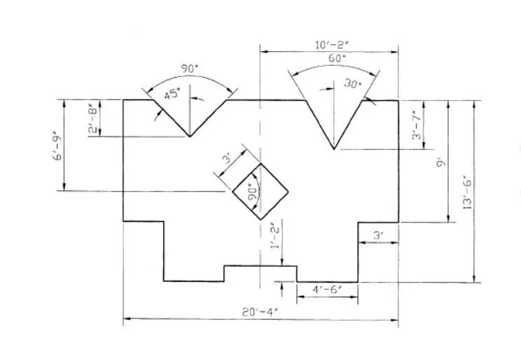
Procedure:
- Using advanced setting, set to engineering units precision to 0'0"
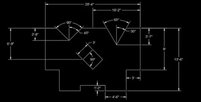
- Using line command, draw 10'2" horizontal line, 9' vertical line, 3' horizontal line, 4'6" vertical line and 1'2" vertical line.
- Using Mirror command, move the above lines at centre axis
- Using Offset command, offset the 20'4" to a distance of 6'9" and 13'6" to a distance of 10'2"
- Using Rectangle command, draw a rectangle of length and width of 3' from the centre point of the Offsetted line.
- Using the Move command, move the centre of the rectangle to the centre of Offsetted line.
- Now using rotate command, rotate the rectangle by 45 degree
- Using offset command, offset 20'4" to a distance of 2'8" with polar tracking on, draw an angle of 90 degree.
- Using offset command, offset 20'4" to a distance of 3'7" with polar tracking on, draw an angle of 60 degree.
- Now using the Trim command, trim off the unwanted lines.
Result: