Creating a Floor plan, Footing detail and Isometric view using AutoCad
Aim: To Creating a Floor plan, Footing detail and Isometric view using AutoCad
Introduction: AutoCadd software offers soo many commands and have many features like camphering the rectangle, fillet rectangle, creating offset, dimension, ortho mode, moving, copying, creating mirror image, using isometeric mode, etc thus making the work easy, thus reduces the time of designing.
C1. Cross-section of Load-bearing wall
Procedure:
- Start by typing QNEW in the command box
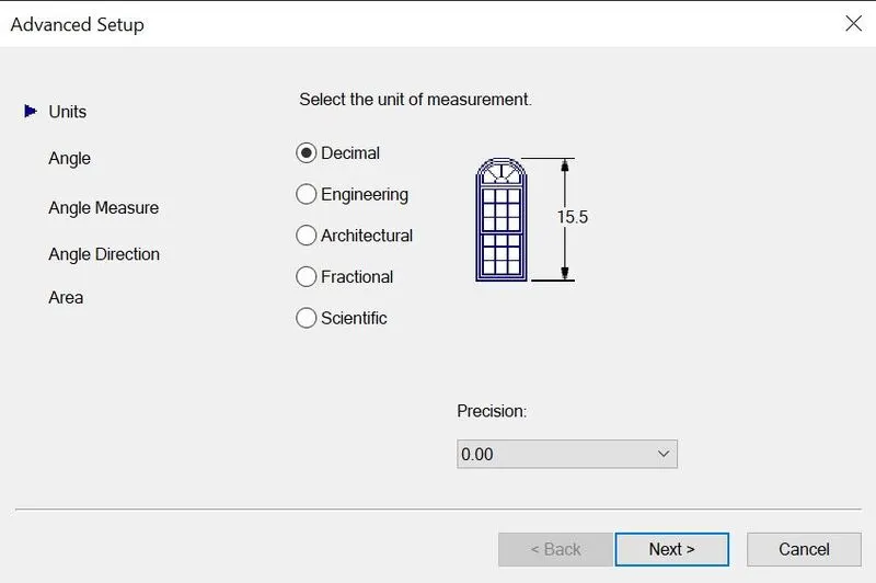
- Advanced Setup > Set the Units, Angle, Angle measure, Angle direction and area
- .
- Specify the Limits
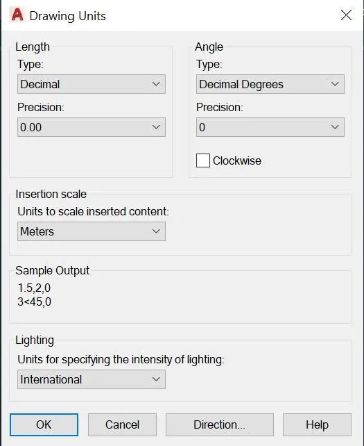
- Set the Unit as meter
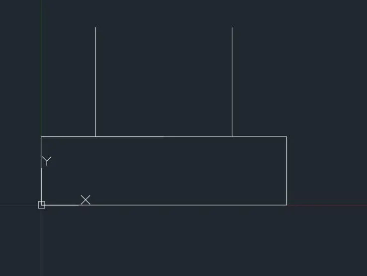
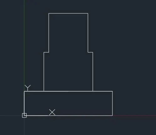
- Type Rectangle from the command box and specify the first point as (0,0) and second point as (0.9,0.25)
- Now Click Esc
- Now use the Line command and specify the start point as (0.2,0.4)
- Using the offset commad, give the offset distance as 0.5
- Specify the next point as (0.2,0.65)
- (0.25,0.65)
- Esc., then specify the next point (0.25,1.05)
- Using the Offset command, take the offset of this line with the offset distance of 0.4. Now join the lines.
- Now using the Rectangular command, create a rectangle 0.05 distance from the previously created one with the length 0.4 and width 0.4
- Command: LINE
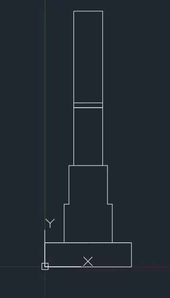
- Specify first point: 0.3,1.05
- Specify next point or [Undo]: 0.3,1.65
- Specify next point or [Undo]: 0.6,1.65
- Command: LINE
- Specify first point:
- Specify next point or [Undo]: 0.6,1.05
- Specify next point or [Undo]: *Cancel*
- Command: LINE
- Specify first point:
- Specify next point or [Undo]:
- Specify next point or [Undo]: *Cancel*
- Command: OFFSET
- Current settings: Erase source=No Layer=Source OFFSETGAPTYPE=0
- Specify offset distance or [Through/Erase/Layer] <0.40>: 0.05
- Select object to offset or [Exit/Undo] :
- Command: LINE
- Specify first point:
- Specify next point or [Undo]: *Cancel*
- Command: LINE
- Specify first point:
- Specify next point or [Undo]: 0.3,2.65
- Specify next point or [Undo]: *Cancel*
- Command: OFFSET
- Current settings: Erase source=No Layer=Source OFFSETGAPTYPE=0
- Specify offset distance or [Through/Erase/Layer] <0.05>: 0.3
- Select object to offset or [Exit/Undo] :
- Specify point on side to offset or [Exit/Multiple/Undo] :
- Select object to offset or [Exit/Undo] : *Cancel*
- Command: LINE
- Specify first point:
- Specify next point or [Undo]:
- Specify next point or [Undo]: *Cancel*
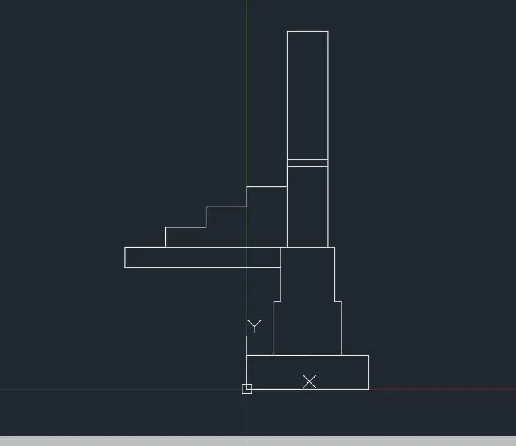
- Now make a line of 1.15 anywhere and using move command move the line.
- Command: _move 1 found
- Specify base point or [Displacement] :
- Specify second point or :
- Command: OFFSET
- Current settings: Erase source=No Layer=Source OFFSETGAPTYPE=0
- Specify offset distance or [Through/Erase/Layer] <0.30>: 0.15
- Specify point on side to offset or [Exit/Multiple/Undo] :
- Select object to offset or [Exit/Undo] : *Cancel*
- Now draw the stairs with 0.15 rise and 0.3 thread. Using move and copy options, move to required portion
Result:
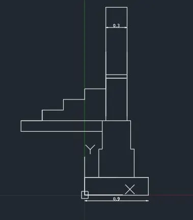
C2. Cross-section of Isolated footing
Procedure:
- Start by typing QNEW in the command box
- Advanced Setup > Set the Units, Angle, Angle measure, Angle direction and area
- .
- Specify the Limits
- Set the Unit as meter
- Setting the initial point (0,0)
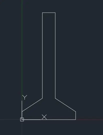
- Command: LINE
- Specify first point: 0,0
- Specify next point or [Undo]: @0.15<90
- Specify next point or [Undo]: @0.455<33.341
- Specify next point or [Close/Undo]: @1.60<90
- Specify next point or [Close/Undo]: @0.24<0
- Specify next point or [Close/Undo]: @1.60<270
- Specify next point or [Close/Undo]: @0.455<326.659
- Specify next point or [Close/Undo]: @0.15<270
- Specify next point or [Close/Undo]:
- Specify next point or [Close/Undo]: *Cancel*
- Command: LINE
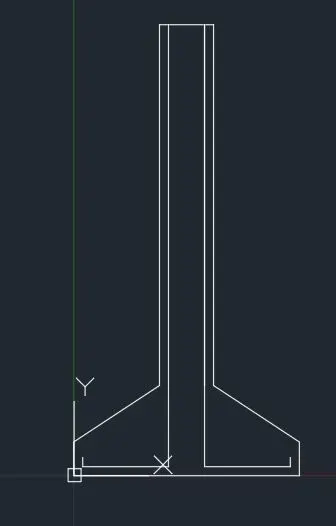
- Specify first point: 0.04,0.04
- Specify next point or [Undo]: *Cancel*
- Command: LINE
- Specify first point: 0.04,0.08
- Specify next point or [Undo]: 0.04,0.04
- Specify next point or [Undo]: 0.42,0.04
- Specify next point or [Close/Undo]: 0.42,2.0
- Specify next point or [Close/Undo]: *Cancel*
- Similarily using the Mirror command, create the main reinforcement bars
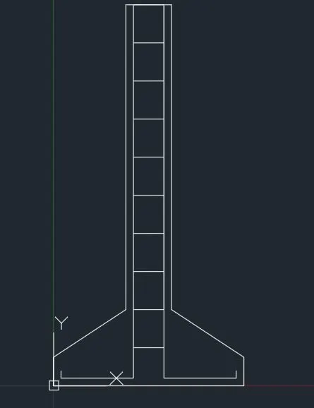
- Command: OFFSET
- Specify offset distance or [Through/Erase/Layer] <0.04>: 0.20
- Specify point on side to offset or [Exit/Multiple/Undo] : M
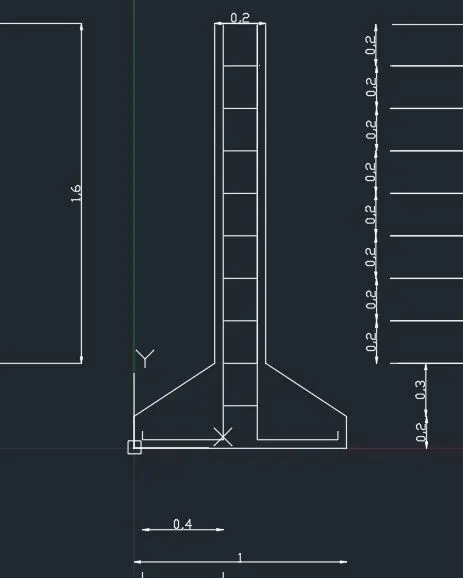
Result:
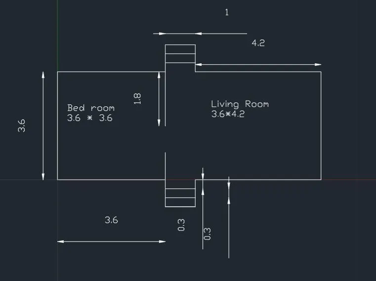
C3. Line diagram of Two bedroom building
Procedure:
- Start by typing QNEW in the command box
- Advanced Setup > Set the Units, Angle, Angle measure, Angle direction and area
- .
- Specify the Limits
- Set the Unit as meter
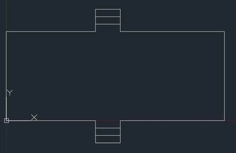
- Command: LINE
- Specify first point: 0,0
- Specify next point or [Undo]: 0,3.6
- Specify next point or [Undo]: 3.6,3.6
- Specify next point or [Close/Undo]: 3.6,4.5
- Specify next point or [Close/Undo]: 4.6,4.5
- Command: OFFSET
- Current settings: Erase source=No Layer=Source
- OFFSETGAPTYPE=0
- Specify offset distance or [Through/Erase/Layer] <1.00>: 0.3
- Specify point on side to offset or [Exit/Multiple/Undo] <Exit>: M
- Specify point on side to offset or [Exit/Undo] <next object>:
- Specify point on side to offset or [Exit/Undo] <next object>:
- Specify point on side to offset or [Exit/Undo] <next object>: *Cancel*
- Command: OFFSET
- Current settings: Erase source=No Layer=Source OFFSETGAPTYPE=0
- Specify offset distance or [Through/Erase/Layer] <0.30>: 0.3
- Select object to offset or [Exit/Undo] <Exit>:
- Specify point on side to offset or [Exit/Multiple/Undo] <Exit>:
- Select object to offset or [Exit/Undo] <Exit>:
- Specify point on side to offset or [Exit/Multiple/Undo] <Exit>:
- Select object to offset or [Exit/Undo] <Exit>: *Cancel*
- Command: LINE
- Specify first point:
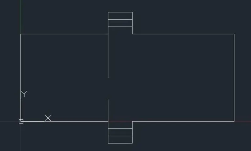
- Specify next point or [Undo]: 3.6,1.8
- Specify next point or [Undo]: *Cancel*
- Command: LINE
- Specify first point:
- Specify next point or [Undo]: 3.6,0.9
- Specify next point or [Undo]: *Cancel*
Result:
C4. Cross-section of Load bearing wall with foundation details
Procedure:
- Start by typing QNEW in the command box
- Advanced Setup > Set the Units, Angle, Angle measure, Angle direction and area
- .
- Specify the Limits
- Set the Unit as meter
- Use the Rectangle command and create a rectangle
- Specify first corner point or [Chamfer/Elevation/Fillet/Thickness/Width]: 0,0
- Specify other corner point or [Area/Dimensions/Rotation]: 0.9,0.45
- Command: LINE
- Specify first point: 0.15,0.45
- Specify next point or [Undo]: 0.15,0.85
- Specify next point or [Undo]: 0.2,0.85
- Specify next point or [Close/Undo]: 0.2,1.15
- Specify next point or [Close/Undo]: 0.25,1.15
- Specify next point or [Close/Undo]: 0.25,1.75
- Specify next point or [Close/Undo]: 0.65,1.75
- Specify next point or [Close/Undo]: *Cancel*
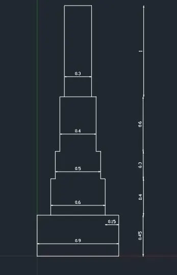
- Command: OFFSET
Current settings: Erase source=No Layer=Source OFFSETGAPTYPE=0
Specify offset distance or [Through/Erase/Layer] <0.40>: 0.6
Select object to offset or [Exit/Undo] <Exit>:
Specify point on side to offset or [Exit/Multiple/Undo] <Exit>:
Select object to offset or [Exit/Undo] <Exit>: *Cancel* - Command: OFFSET
Current settings: Erase source=No Layer=Source OFFSETGAPTYPE=0
Specify offset distance or [Through/Erase/Layer] <0.60>: 0.5
Select object to offset or [Exit/Undo] <Exit>:
Specify point on side to offset or [Exit/Multiple/Undo] <Exit>:
Select object to offset or [Exit/Undo] <Exit>: *Cancel* - Command: OFFSET
Current settings: Erase source=No Layer=Source OFFSETGAPTYPE=0
Specify offset distance or [Through/Erase/Layer] <0.50>: 0.4
Select object to offset or [Exit/Undo] <Exit>:
Specify point on side to offset or [Exit/Multiple/Undo] <Exit>:
Select object to offset or [Exit/Undo] <Exit>: *Cancel* - Command: _line
Specify first point:
Specify next point or [Undo]:
Specify next point or [Undo]: *Cancel* - Command: _line
Specify first point:
Specify next point or [Undo]:
Specify next point or [Undo]: *Cancel* 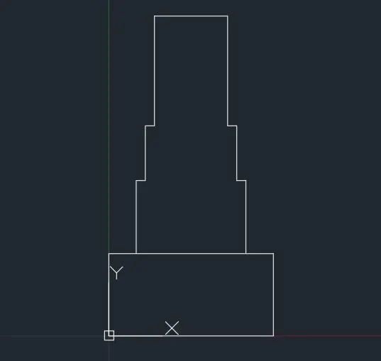
- Command: LINE
Specify first point:
Specify next point or [Undo]:
Specify next point or [Undo]: *Cancel* - Command: OFFSET
Current settings: Erase source=No Layer=Source OFFSETGAPTYPE=0
Specify offset distance or [Through/Erase/Layer] <0.40>: 0.15
Select object to offset or [Exit/Undo] <Exit>:
Specify point on side to offset or [Exit/Multiple/Undo] <Exit>:
Select object to offset or [Exit/Undo] <Exit>:
Specify point on side to offset or [Exit/Multiple/Undo] <Exit>:
Select object to offset or [Exit/Undo] <Exit>: *Cancel* - Command: _line
Specify first point:
Specify next point or [Undo]:
Specify next point or [Undo]: *Cancel* 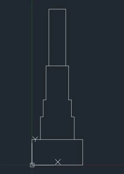
Result:
C5. Isometric view of step
Procedure:
- Start by typing QNEW in the command box
- Advanced Setup > Set the Units, Angle, Angle measure, Angle direction and area
- .
- Specify the Limits
- Set the Unit as meter
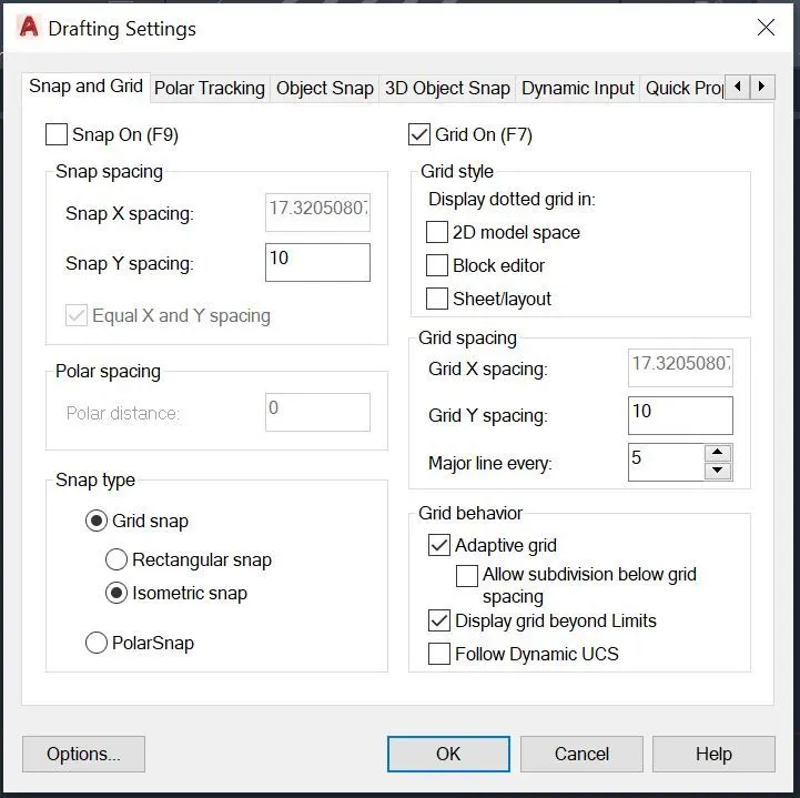
- Now in snap setting, select isometric snap and toggle appropriately between Isoplane left, isoplane top and isoplane right.
- Switch on the ortho mode
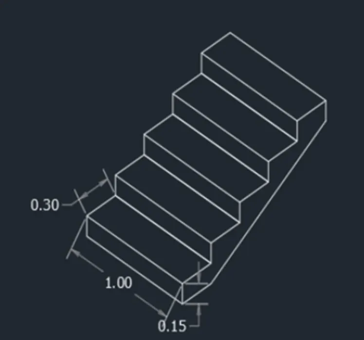
- Isoplane right: Command, line of length 0.15 and 0.30 ; 5 times
- Isoplane left: Command, Line of length 0.15 and 0.30 ; 5 times and join the lines
- For the waist slab, From bottom edge in isoplane top, a line of 0.30 and top edge in isoplane right, a line of 0.15 is created. And join them.
Result:
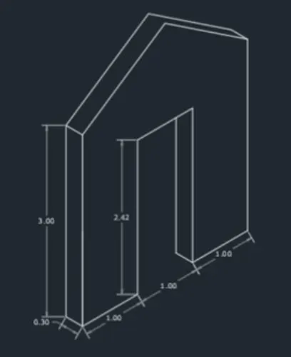
C6. Isometric view of Gable wall
Procedure:
- Start by typing QNEW in the command box
- Advanced Setup > Set the Units, Angle, Angle measure, Angle direction and area
- .
- Specify the Limits
- Set the Unit as meter
- Now in snap setting, select isometric snap and toggle appropriately between isoplane left, top and right.
- Keep the ortho mode on
- Command LINE selecting a random point
- Isoplane right: 3m, 1m, 2.42m, 1m, 2.42m, 1m and 3m in correct direction.
- Isoplane left: From left 3m line to 0.30m and 0.30m from top and bottom and Join the lines.
- Draw a perpendicular line in the middle of the gabble wall with a bottom distance of 4m.
- Now join it in triangular form.
- Isoplane top: 0.30m from top triangular edge and 0.30m from top right corner and join it.
Result: