To calculate the dead , live and wind load for RC residential structure and to apply them using TSD
Questions:-
- Calculate dead load in design report based on IS code and apply dead load on the model
- Finishes of 50mm
- Slab thickness as per the design
- Brick wall load
- Roofing load
- Calculate live load in design report based on IS code and apply dead load on the model
- Generate manual wind loading in the design report based IS code as per the following input
- Basic wind speed = 50m/s
- Terrain category 2
4. Based on the above calculation apply the loadings on the model.
Ans=
AIM:- To explain the answer for each and every question from 1 to 4.
INTRODUCTION:- In this section of question from 1 to 4, I used Tekla structural designer software to answer these question. Besides this, I have used some reference from recorded video session of skill-lync. Loads cases and load combinations are generated, assigned for the structure using tekla and validation of those loads is an important part of Tekla Structural Designer as it ensures a valid model for the analysis and design routines. Imposed Loads are assigned according to IS 875 Part 2
PROCEDURE:- Here first I will mention question one by one then answer then in the same manner.
Question- 1. Calculate dead load in design report based on IS code and apply dead load on the model
- Finishes of 50mm
- Slab thickness as per the design
- Brick wall load
- Roofing load
Ans=
Dead Load calculation
Slab load : model slab in software
Finishes : 50mm x 24 KN/m^3 = 0.05 x 24 = 1.2 KN/m2
Brick wall width = 225mm
Unit weight = 20 KN/m^3
Floor height (Ground floor to First floor) = 3.6m
Brick wall loading for ground floor = 20 x (225/1000) x 3.6 = 16.2 KN/m
Floor height (First floor to roof ) = 3.6 m
Brick wall loading for first floor = 20 x (225/1000) x 3.6 = 16.2 KN/m
Parapet wall height (on roof) = 1.5m
Brick wall width for parapet wall= 150mm
Brick wall loading for parapet wall= 20 X (150/1000) X 1.5 = 4.5 KN/m
Roofing load based on purlin size :1.5KN/m^2
Ceiling loading 0f 0.3KN per sq m
PROCEDURE:-
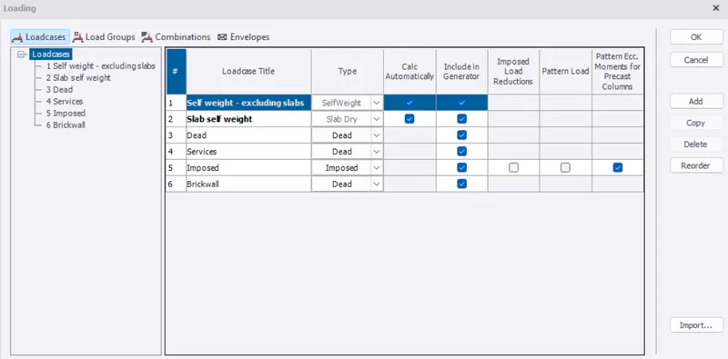
- Generate load cases
- Generate load combinations
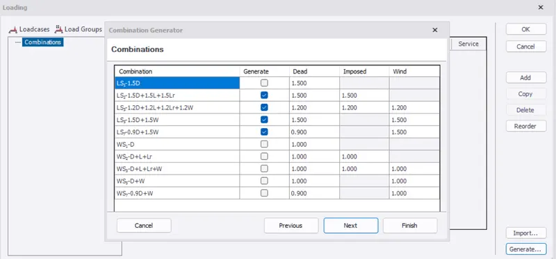
- Now click on Load combinations in load tab
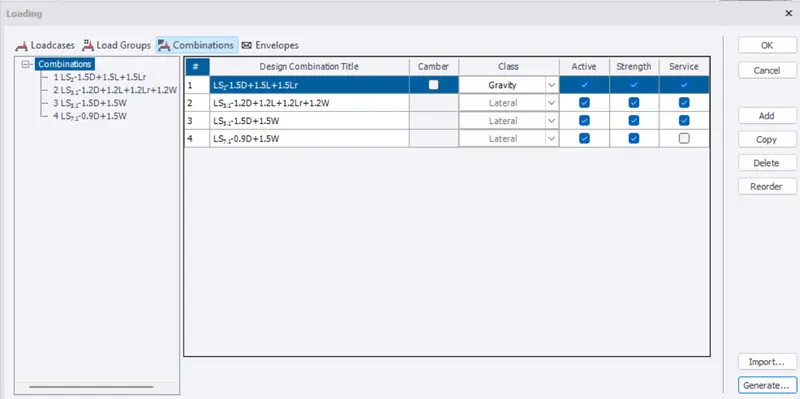
- Click on generate, we get initial paramters. Check and click on next
- Select dead load at the bottom
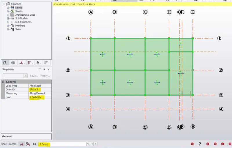
- Now select area load from panel load (Load tab)
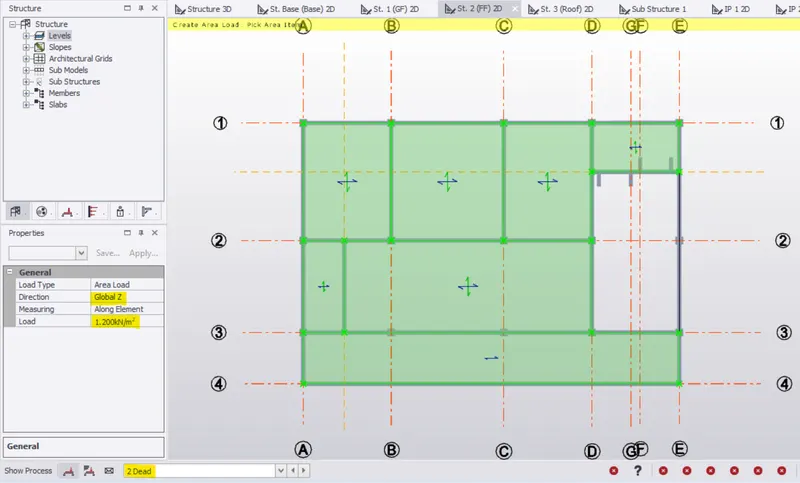
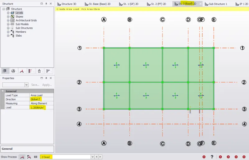
- Select area load = 1.2KN/m2 in ground floor and first floor and apply it
- Ground floor :
- First floor
- Roof
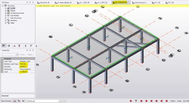
- Now to apply brick load to Groundfloor, Firstfloor
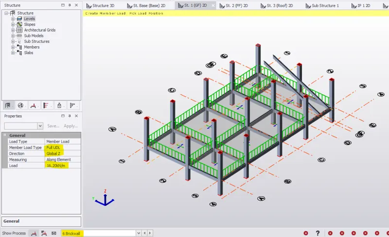
- Select "Full udl" in load tab and apply brick load = 16.2 KN/m for groundfloor and First floor = 16.2 KN/m
- Groundfloor
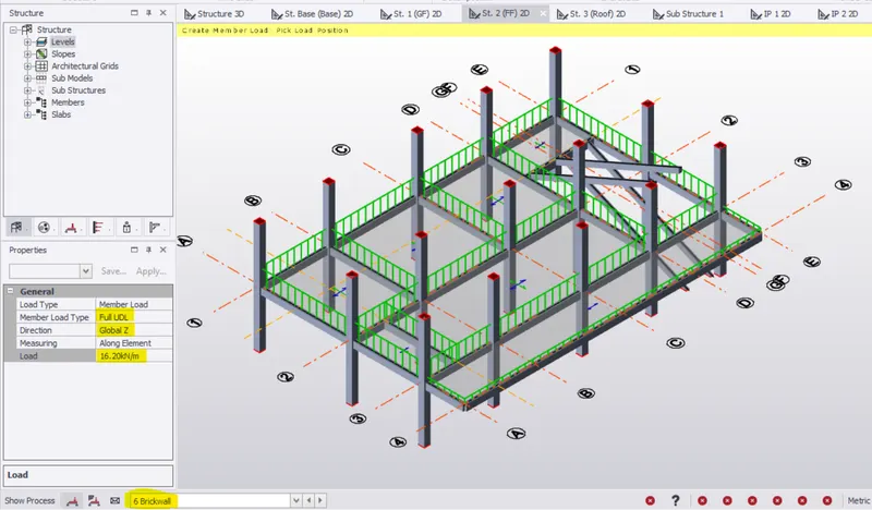
- First floor
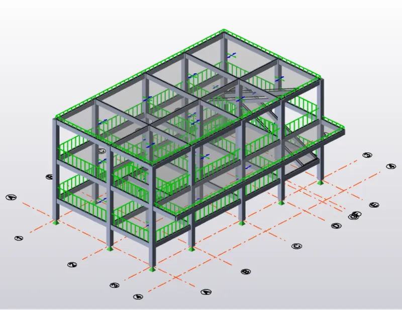
- We will apply brick wall load as 16.2 KN/m and parapet wall load in varanda side also as 4.5 KN/m
- Roof
- We will apply 4.5 KN/m as parapet wall load
RESULTS:-
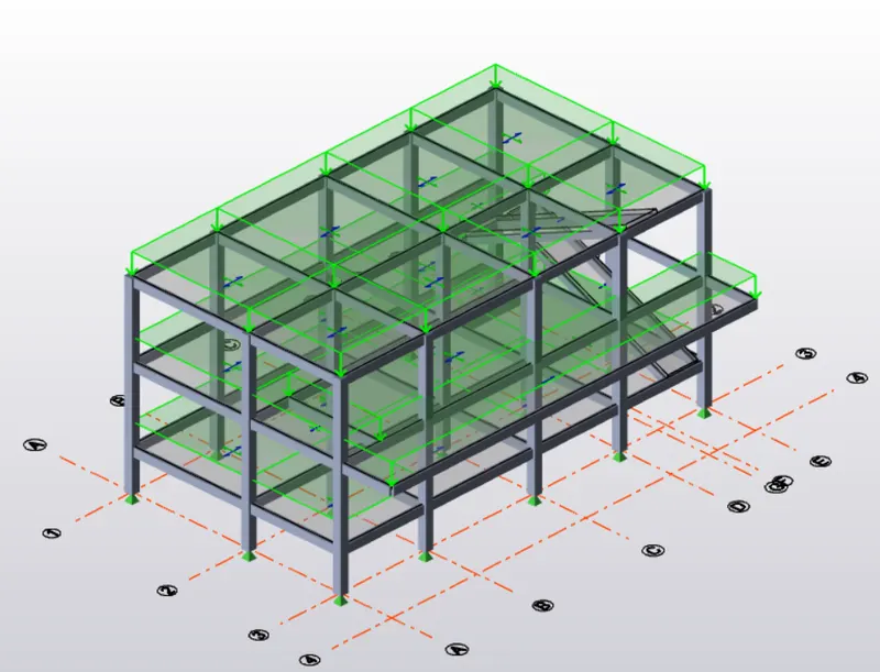
Question- 2. Calculate live load in design report based on IS code and apply live load on the model
Ans=
Loads cases and load combinations are generated, assigned for the structure using tekla and validation of those loads is an important part of Tekla Structural Designer as it ensures a valid model for the analysis and design routines. Imposed Loads are assigned according to IS 875 Part 2
Work areas without machinery/equipments = 2.5KN/m^2
Work areas with machinery/equipments (Heavy) = 10KN/m^2
Staircase : 4KN/m^2
Toilets : 2KN/m^2
Canteen : 3KN/m^2
Store room : 2.4KN/m^2
Conference room : 4KN/m^2
Meeting room : 4KN/m^2
Reception Room : 4 KN/m^2
Office room : 4KN/m^2
Manager room : 4KN/m^2
Corridor : 4KN/m^2
Roof access not provided is taken as : 0.75KN/m2
PRODEDURE :
- Now click on imposed loads at bottom
- Select area load in the panel loads
- Assign loads on the all floors according to the IS 875part 2
- Ground floor
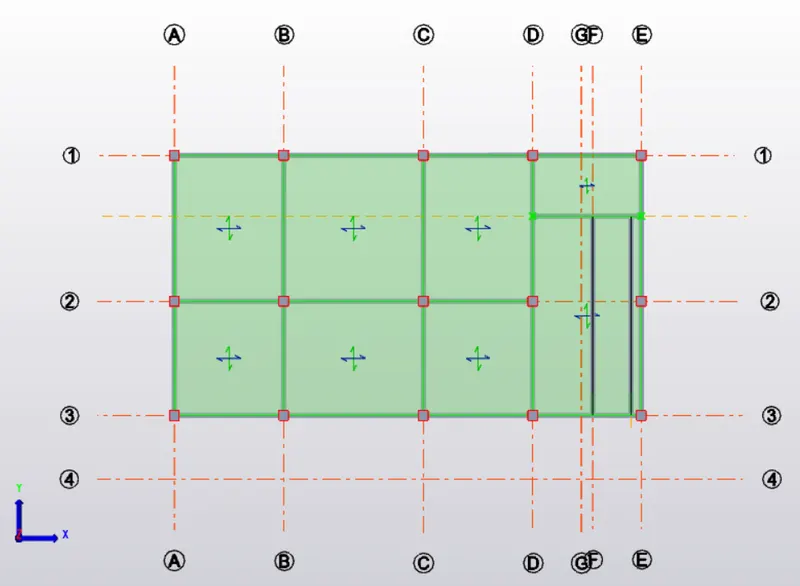
- First Floor
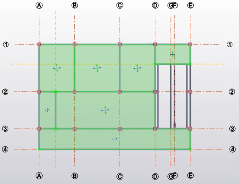
- Roof access not provided is taken as : 0.75KN/m2
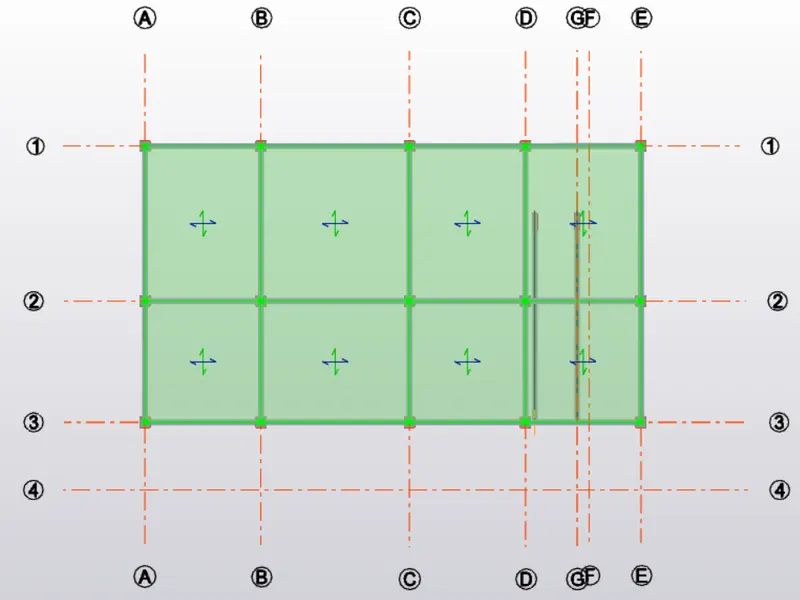
RESULTS :
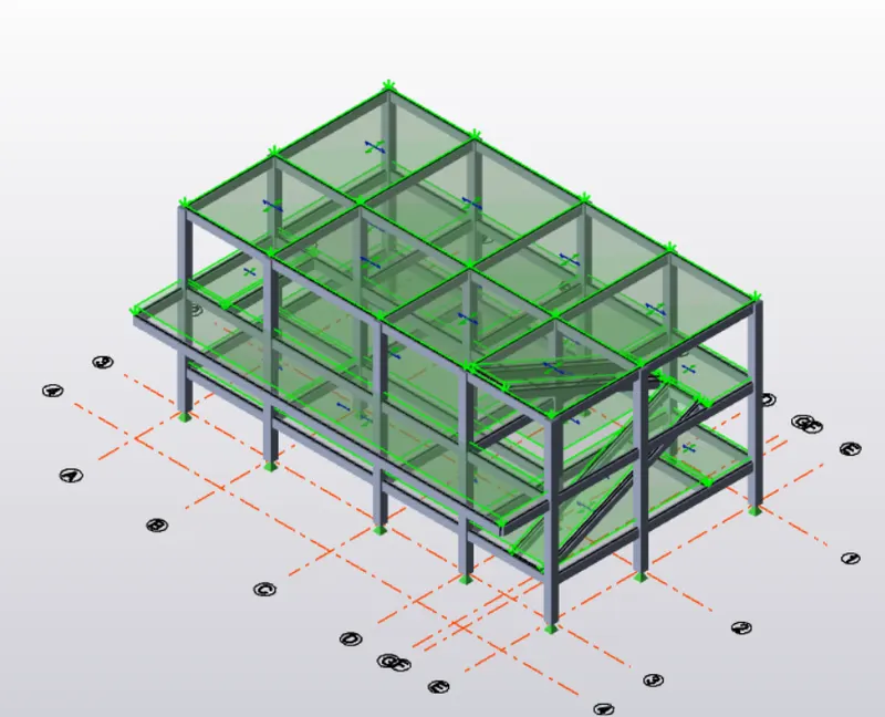
Question- 3. Generate manual wind loading in the design report based IS code as per the following input
- Basic wind speed = 50m/s
- Terrain category 2
Ans=
Wind load calculation :
Wind speed taken as 50m/s
Terrain category is given as 2
Vb = Basic wind speed which is given as 50m/s
Normally basic wind speed is selected from appendix A of code book IS 875 III which is given based on wind speed in various cities
Design wind speed Vz= Vb*K1*K2*K3*K4
Where Vz depends on risk level, terrain roughness, height, size of structure, local topography
K1 = Probability factor
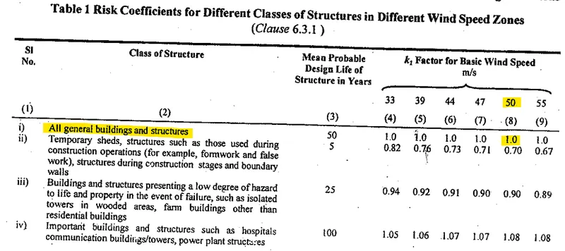
It is taken from table 1 of IS 875 III
Life of structure is taken as 50 yrs and wind speed is given as 50m/s. Based on this K1 =1
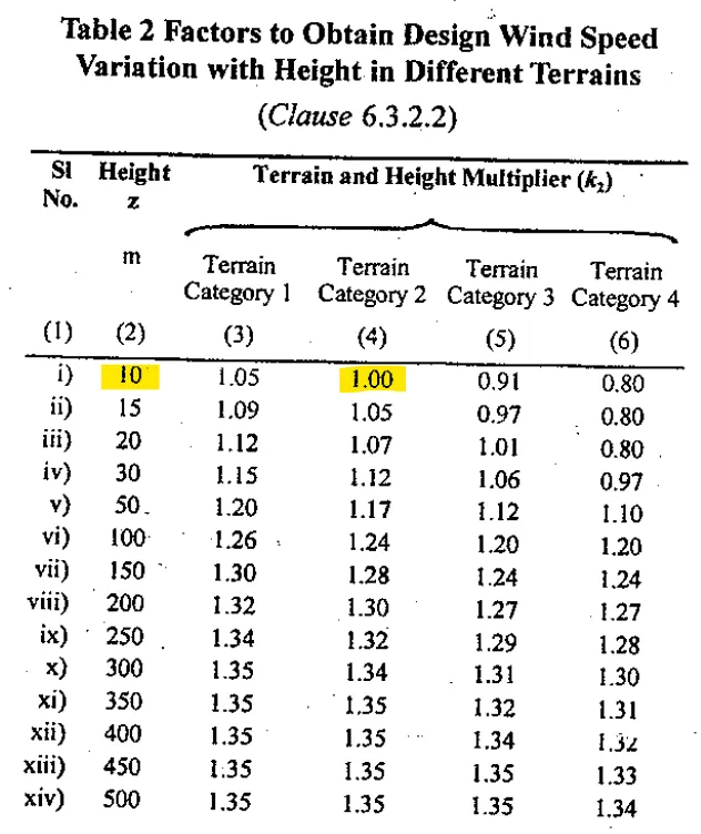
K2 = Terrain, height, structure factor which is taken from table 2 = 1.00
K3 = Topography factor which is taken as 1 (θ<3 = 1 and θ>3 = 1 to 1.36)
K4 = Importane factor for cyclonic region K4 is taken as 1.15
Where K4 = 1.3 Structure for post cyclonic importance
= 1.15 Industrial structure
= 1 All other structure
RESULT:-
- Design wind speed Vz = Vb x K1 x K2 x K3 x K4 = 50 x 1 x 1 x 1 x 1.15 = 57.5 m/s
- Design wind pressure = Pz = 0.6 x Vz^2 = 1983.75 N/m2 = 1.98 KN/m2
Question- 4. Based on the above calculation apply the loadings on the model.
Ans=
INTRODUCTION:
- Wind speed = 50m/s
- Life period = 50yrs
- Terrain category = 2
- Design wind speed Vz = Vb x K1 x K2 x K3 x K4 = 50 x 1 x 1 x 1 x 1.15 = 57.5 m/s
- Design wind pressure = Pz = 0.6 x Vz^2 = 1983.75 N/m2 = 1.98 KN/m2
- Length = 19.225, Width = 10.7m, Height = 16.88m
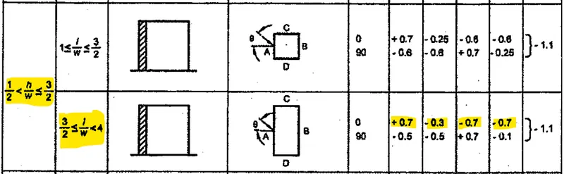
- L/W = 1.79 and H/W = 0.86
- External pressure coefficients for wall is taken from table 5 IS 875 III (H/W=1.57)
PROCEDURE:-
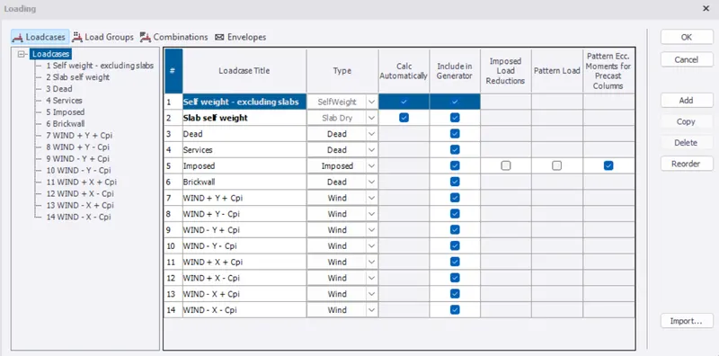
- select Load cases and add wind loads
- Wind load calculation for wall
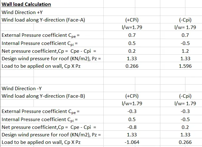
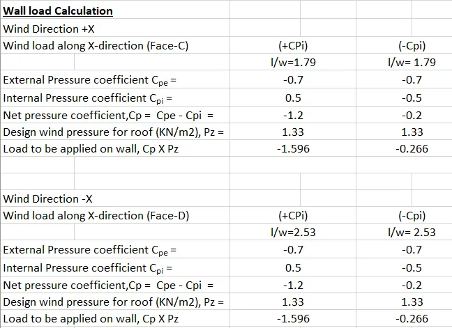
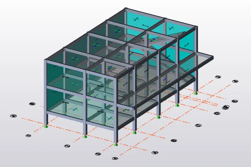
Above calculated loads are applied on the model
Results:-
- Calculation of dead load in design report based on IS code and apply dead load on the model is accomplished.
- Calculation of live load in design report based on IS code and applied live load on the model.
- Manual wind load calculation is completed.
- Calculated wind load is applied on the model. (Tekla model has been attached in the attachment section)