To calculate dead and live load for industrial steel structures and to apply them using TSD
Aim: To calculate dead and live load for industrial steel structures and to apply them using TSD
Introduction:
- Load Calculation
- Load Application
- Valdation
- Here After valdation of the geometry of model, promary and combunation loads to be defined
- Load cases to be created under the LOAD tab. The follwoing primary load cases to be defined
- Self Weight- Pre defined in the software
- Slab Self Weight- Slab self weight defined when we model the slab, Slab self weight To be transfer to the supporting Beam
- Finished
- Services
- Brick Wall
- Imposed Load
- Wind Load
- Seismic Load
- Crane Load
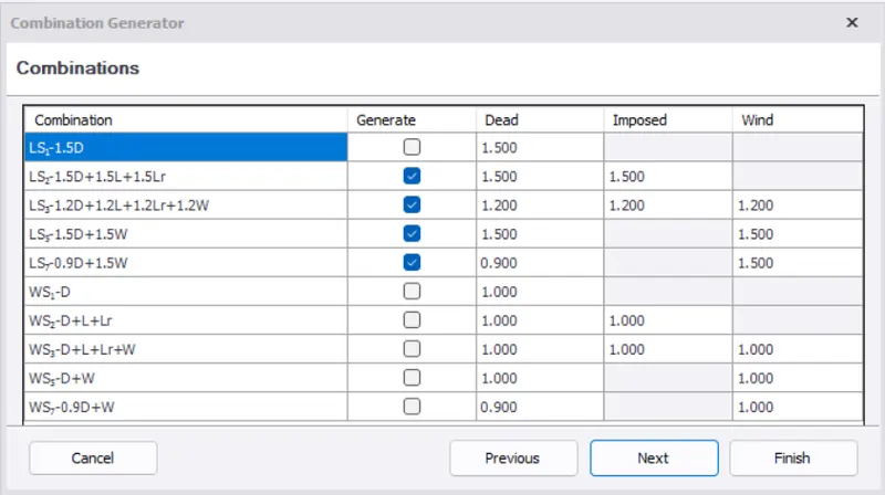
- Load combinations to be generated under the LOAD tab and to be checked with the codal provision
BEFORE STARTING THE CHALLENGE WE FIRSTLY OPEN THE CHALLENGE 3 AND ASSIGN THE WIND PANELS,SLABS AND ROOF PANELS TO START WITH THE LOADING AND LOAD COMBINATIONS.BELOW ARE THE STEPS TO DO THE SAME
Step -1
Take Challenge -3 Model for creating Wall ,roof panel and Slab
- Open Tekla Software from My disktop
- Go to the file menu
- Open --> Recenr document--> STEEL BUILDING.tsmd File
- Then Select FRAME G 2D
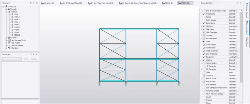
- And then change the column colours for showing the different elements
- And also choose the colour of Wall panel, Roof panels, and etc..
- Shown in the below diagram is a result of changed column colour
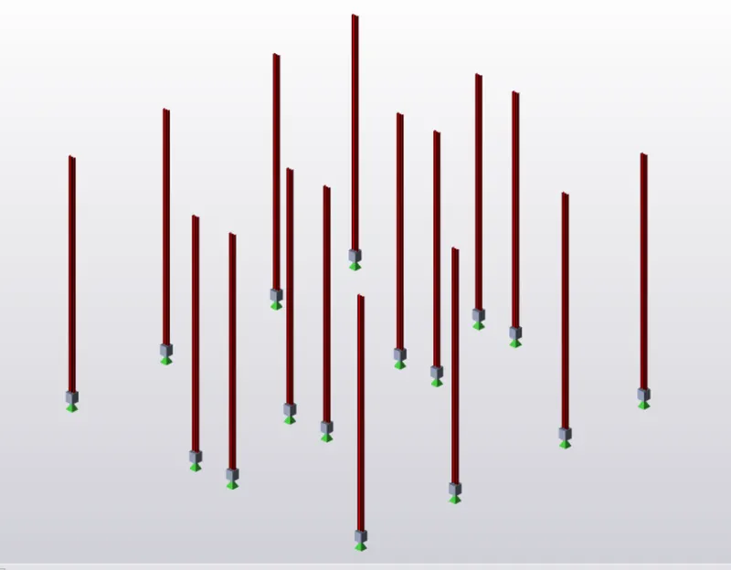
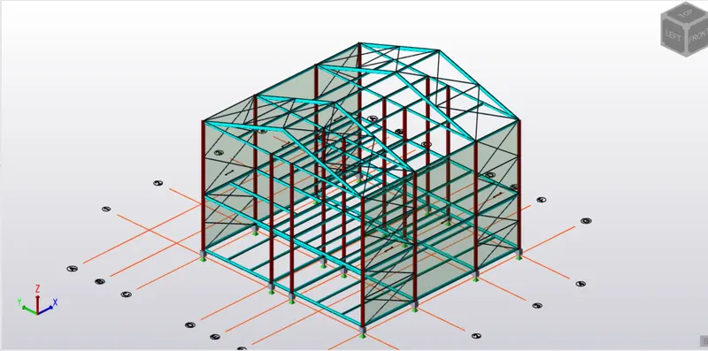
Step-2: Model the Wall Panel:
- Now select the WALL Panel from Under the Model tab is called Walls and Loading objects here
- Select Wall Panel
- Pick the point-1,2,3,4
- Press Escape
- Similarly all the wall Panel are created by show in the figure
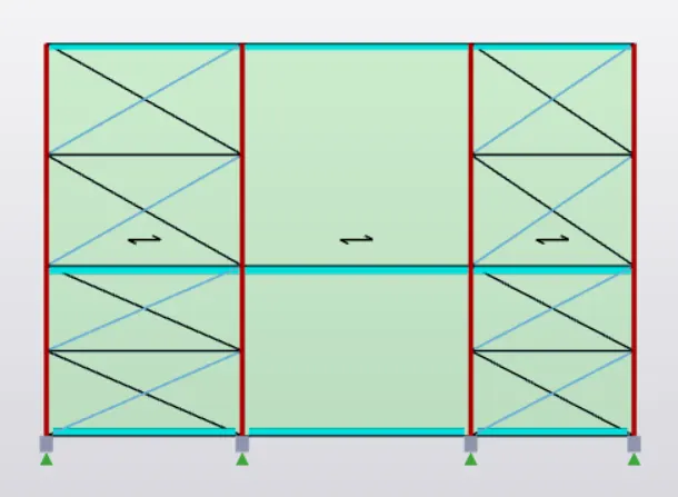
- Now we need to validate for if errors appears or not
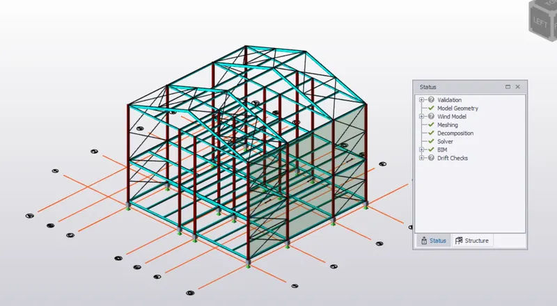
- Hence no error
- And Copy the Wall panel for the other side
- Select --> Pick the refernece point--> Pick The New Position
Step-3: Model the Roof Panel:
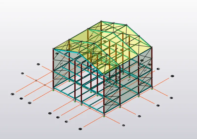
- As above the similar procedure is to be followed to model the roof panel
- As shown in the below diagram and also validate the Roof panel
Step-4: Model the slab:
i. Ground Floor Slab 1:
- Go to the Manage property
- Select the New-->Slab-->General slab
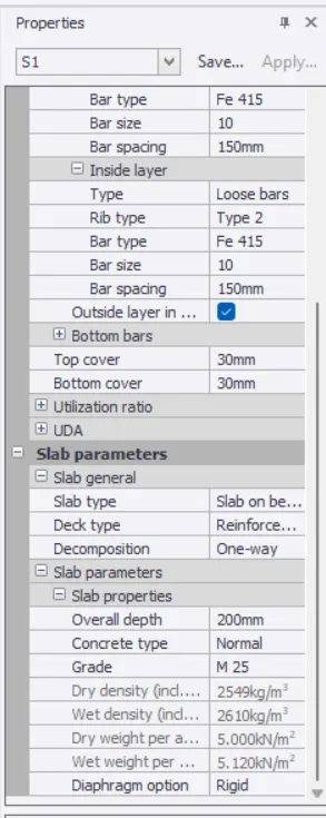
- Change the Name as S1
- Now to provide the Slab type as: Slab on Beam
- Deck Type: Reinforced Concrete
- Decomposition: One-way slab
- Overall Depth: 200mm
- Grade : M25
- And aslo to provided the Rib type: type 2
- And Bar type, Bar size, Bar sapcing also as given below value
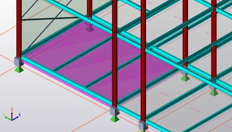
- Now Model the Slab
- Slec the Slab option under the Model tab
- Select property as S1
- Then Rotation angle is :90
- Select Bay
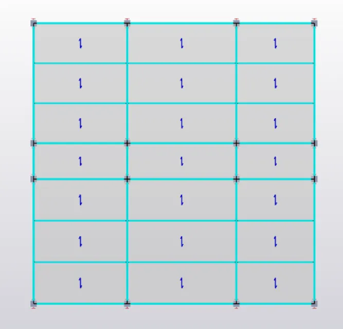
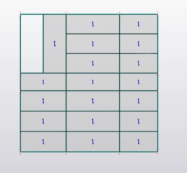
ii.First Floor Slab :
- Similarly Created Firsyt floor Slab
- Property's:
ii.Roof Flat Slab :
- Go to the Manage property
- Select the New-->Slab-->General slab
- Change the Name as S2
- Now to provide the Slab type as: Slab on Beam
- Deck Type: Reinforced Concrete
- Decomposition:Two-way slab
- Overall Depth: 200mm
- Grade : M25
- And aslo to provided the Rib type: type 2
- And Bar type, Bar size, Bar sapcing also as given below value
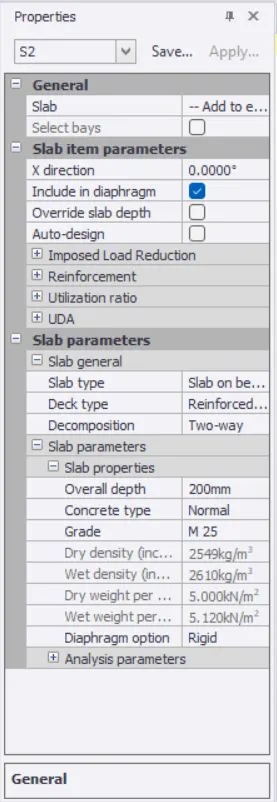
- Now Model the Slab
- Slec the Slab option under the Model tab
- Select property as S2
- Select Bay

Validate the Model:
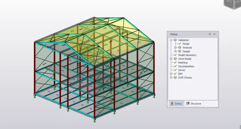
Hence Finished the Model of Wall panel and roof panels and Slab
Now since the roof,slabs and wind walls are provided we can move forward to apply and calcualte loadings and load combinations on the structure
Aim: To Calculate dead load in design report based on IS code and apply dead load on the model
Given:
- Finishes of 50mm
- Slab as per design
- Brickwall 150mm thickness
- Roofing load based on purlin size
- Ceiling loading 0f 0.3KN per sq m
Procedure:
Step-1: To set the Predefined Loads
- Select to the Home
- Under the Load tab There are Various option called Loadcases, Combination Load Group, And Wind Wizard
- First Start with the Loadcases
- Click Loadcases
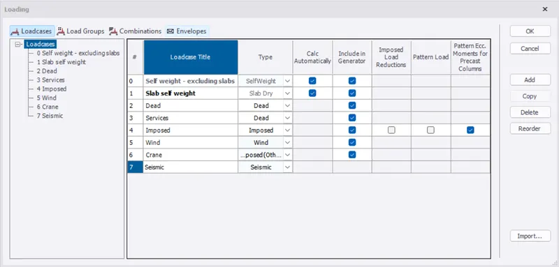
- Predefined Loadcases dialouge box are appear on dispaly with
- Slab self weight , Dead Load, Service Load, Imposed Load
- Now go to Add the Load cases
- Click Add
- Under the type Select the Wind, Seismic and crane Load As Imposed load(other)
- Press OK
- Now Generate the Load Combinations
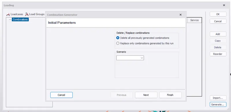
- Click the Generate option
- Slect the Dlete all Previously generated combination -> Next
- Press Next
- Press Next
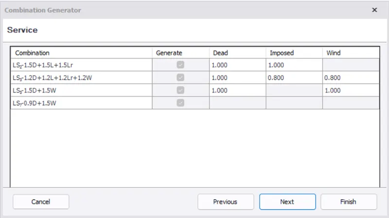
- Press Next
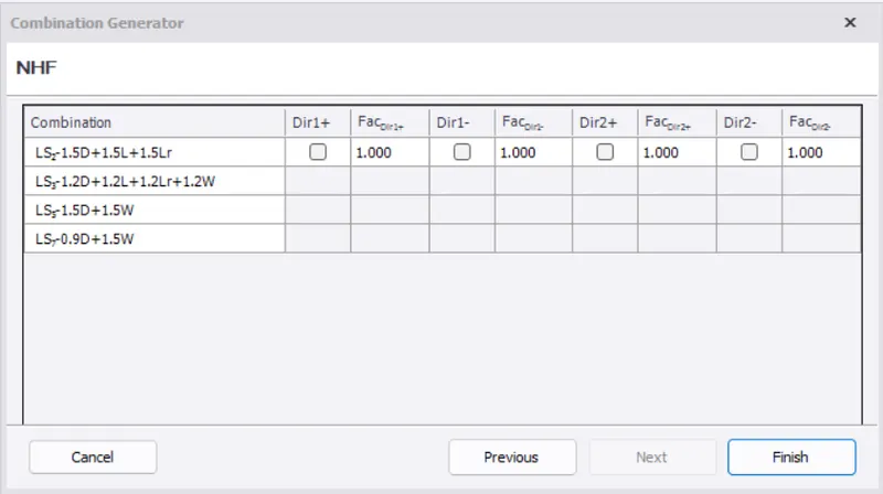
- Click Finish
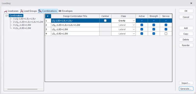
- Now Press OK to be finished Load combination
Load Calculation:
Step-2: To calculate the Dead Load
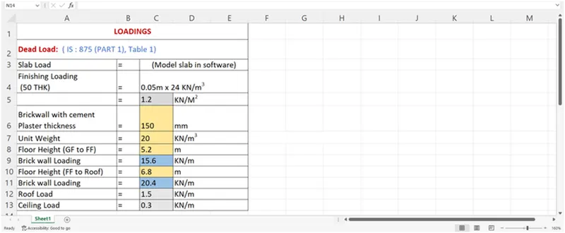
Excel Worksheet for Dead Load Calculation:
- I took all Value of Unit Weight of Bricks and unit weight of Concrete from the Code book (IS-875 (PART 1), Table 1)
- And Here i Calculate the Brick Wall loading by using Formula for= C7*C6*C8/1000= 15.6 KN/m
- Similarly calculated First Floor to Roof =20.5 KN/m
To Apllying Dead Load:
Step-3 : To applying Slab and Roof Panel Load:
i. Ground Floor Slab:
- First Go to Under the Loadcases there is option called : None
- Then select to drag down Select : 2 Dead Load

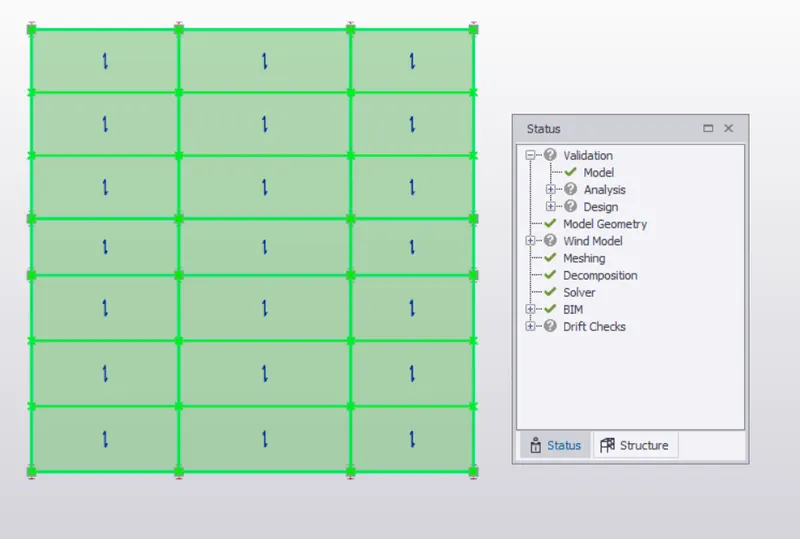
- Under the Deal Load, Select the Area Load for Applying Finishing Load
- Finishing Load is: 1.2 KN/m2
- Under the Area Load We need to select the Load type is: Area Load
- Direction: Global z
- Measuring: Along Elements
- Load : 1.2 KN/m2
- Now Pick Area Item the colour of the Slab is changing
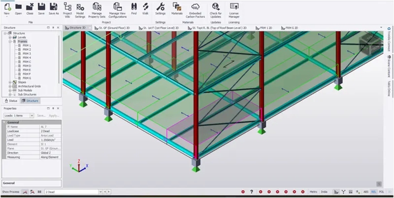
- Validate The Slab model:
ii. First Floor Slab:
- First Go to Under the Loadcases there is option called : None
- Then select to drag down Select : 2 Dead Load
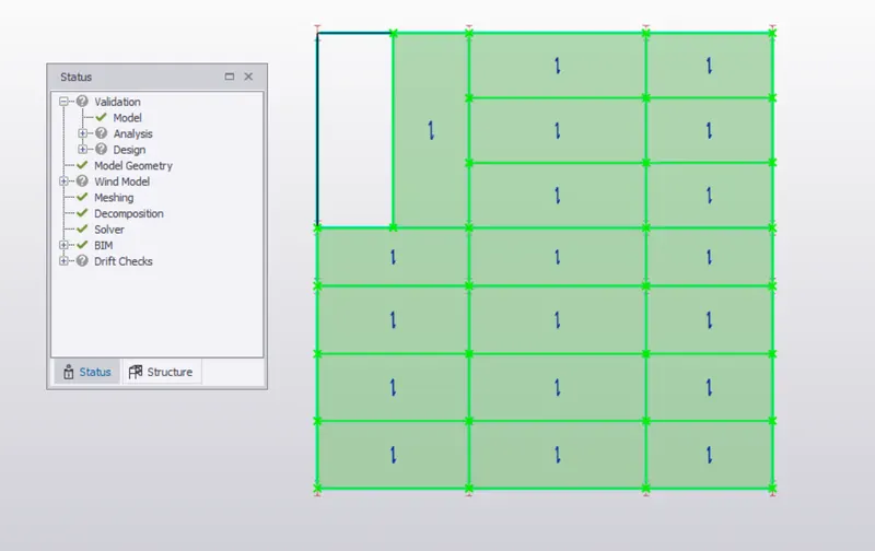
- Under the Deal Load, Select the Area Load for Applying Finishing Load
- Finishing Load is: 1.2 KN/m2
- Under the Area Load We need to select the Load type is: Area Load
- Direction: Global z
- Measuring: Along Elements
- Load : 1.2 KN/m2
- Now Pick Area Item the colour of the Slab is changing
iii. Roof Flat Slab:
- First Go to Under the Loadcases there is option called : None
- Then select to drag down Select : 2 Dead Load
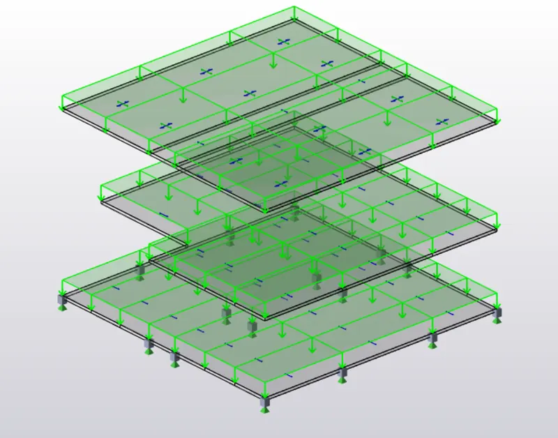
- Under the Deal Load, Select the Area Load for Applying Finishing Load
- Finishing Load is: 1.2 KN/m2
- Under the Area Load We need to select the Load type is: Area Load
- Direction: Global z
- Measuring: Along Elements
- Load : 1.2 KN/m2
- Now Pick Area Item the colour of the Slab is changing
Step-4 : To Apllying Wall Load:
i. Ground Floor Wall:
- First Go to Under the Loadcases there is option called : None
- Then select to drag down Select : 2 Dead Load
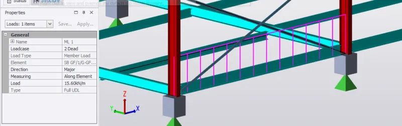
- Under the Load Tab, Select the Full UDL Load As member load
- Wall Load is: 15.6 KN/m
- Under the Area Load We need to select the Load type is: Member Load
- Member Load : Full UDL
- Direction: Global z
- Measuring: Along Elements
- Load : 15.6 KN/m2N
- First we Apply the loading for Outer wall perimeters
- Select the Full UDL
- Pick Load Position
- Properties of Wall load:
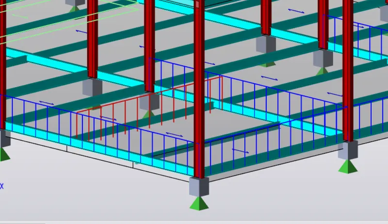
- Finish the Perimeters Load
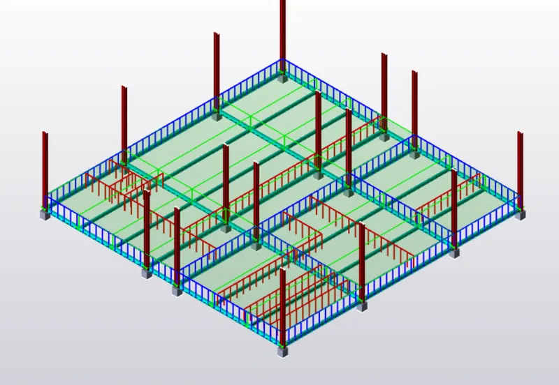
- Now Take Line Load To draw the Wall for wherever Requierd in the Drawing
Validate :
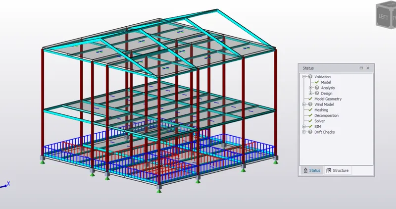
- Hence No Error
Similarly Applying for 1st Floor Wall loading also
ii. First Floor Wall:
- First Go to Under the Loadcases there is option called : None
- Then select to drag down Select : 2 Dead Load
- Under the Deal Load, Select the Full UDL Load As Member load
- Wall Load is: 20.4 KN/m
- Under the Area Load We need to select the Load type is: Member Load
- Member Load : Full UDL
- Direction: Global z
- Measuring: Along Elements
- Load : 20.4 KN/m2N
- First we Apply the loading for Outer wall perimeters
- Select the Full UDL
- Pick Load Position
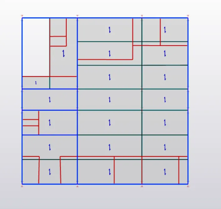
- Finish the Perimeters Load
- Now Take Line Load To draw the Wall for wherever Requierd in the Drawing
Validate:
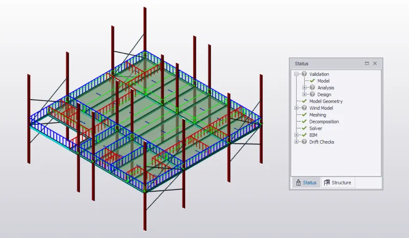
- Hence No Error
iii. Roof Panel Load:
- First Go to Under the Loadcases there is option called : None
- Then select to drag down Select : 2 Dead Load
- Under the Load Tab, Select the Area Load for Applying Member Load
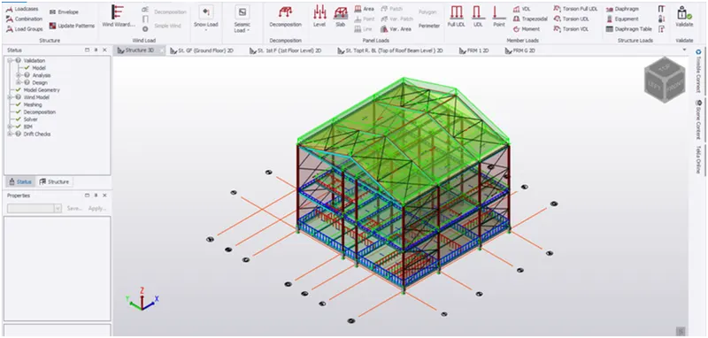
- Roof Load is: 1.5 KN/m2
- Under the Area Load We need to select the Load type is: Area Load
- Direction: Global z
- Measuring: Along Elements
- Load : 1.5 KN/m2
- Now Pick Area Item the colour of the Slab is changing
Validate :
Result:
Question-2
Aim: To Calculate live load in design report based on IS code and apply live load on the model
Given:
- Assume the loading based on IS 875
- Roof loading
- Consider equipment loading as 5KN per sq m
Procedure:
Load Calculation:
Step-1: To calculate the Live Load
Excel Worksheet for Dead Load Calculation:
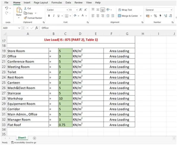
- I took all Value of Live Load from the Code book (IS-875 (PART 1), Table 1)
- Following Below Rooms Of Live Load to be Applied for our Model
To Apllying Live Load:
Step-2: To Applying the Live Load
i. ground Floor
- Select COnstruction Level of Grond Floor
- First Go to Under the Loadcases there is option called : None
- Then select to drag down Select : 4 Imposed

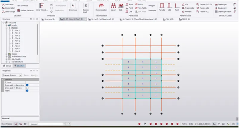
- Then We need to Refer the Room Name and their Live Load from (IS-875 (PART 1), Table 1)
- Under the Load Tab, Select the Area Load for Applying Live Load
- Initial One by One Floor Imposed load to be applied
- Live Load is:2 KN/m2
- Under the Area Load We need to select the Load type is: Area Load
- Direction: Global z
- Measuring: Along Elements
- Load : 2 KN/m2
- Now Pick Area Item the colour of the Floor is changing
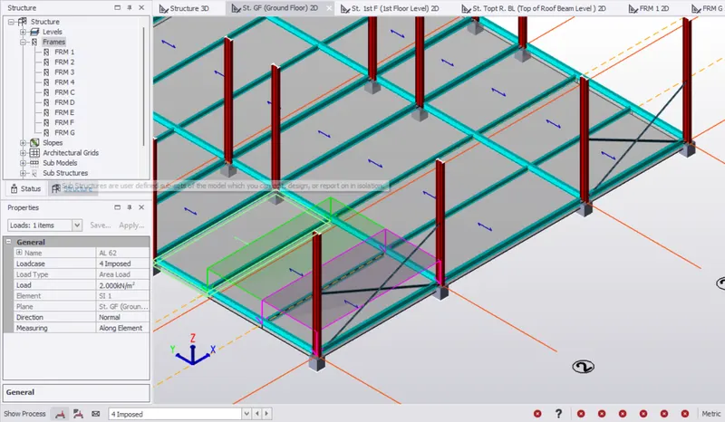
- Now select the Area Load for applying Office Room
- Live Load is:5 KN/m2
- Under the Area Load We need to select the Load type is: Area Load
- Direction: Global z
- Measuring: Along Elements
- Load : 5 KN/m2
- Now Pick Area Item the colour of the Floor is changing
Validate:
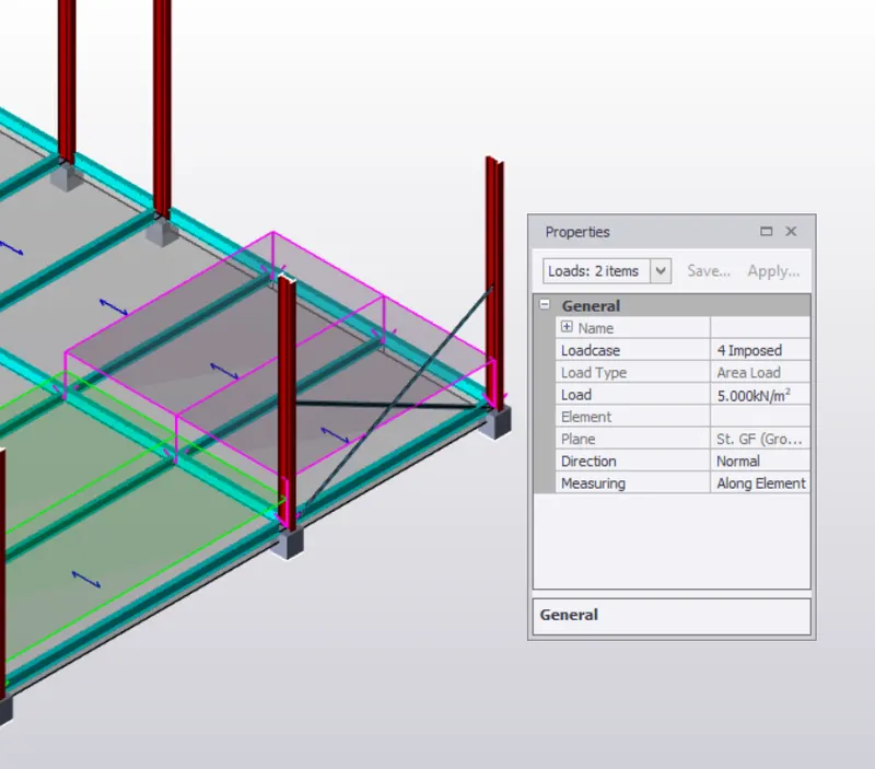
Here Similarly all rooms live load to be applied
Store Room,Conference Room, Meeting Room, Mech& Elect Room, Staricase, Equipment Room, Corridor, Main Admin., Office = 5KN/m2
Office Room, Canteen, Manager Room = 3 KN/m2
Toilet, Rest Room, = 3 KN/m2
Workshop = 10 KN/m2
Flat Roof = 0.7 KN/m2
Similarly all the Load are appied
Validate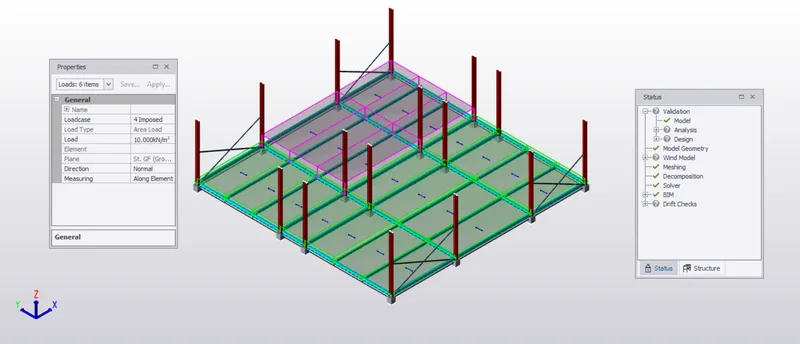
ii. First Floor:
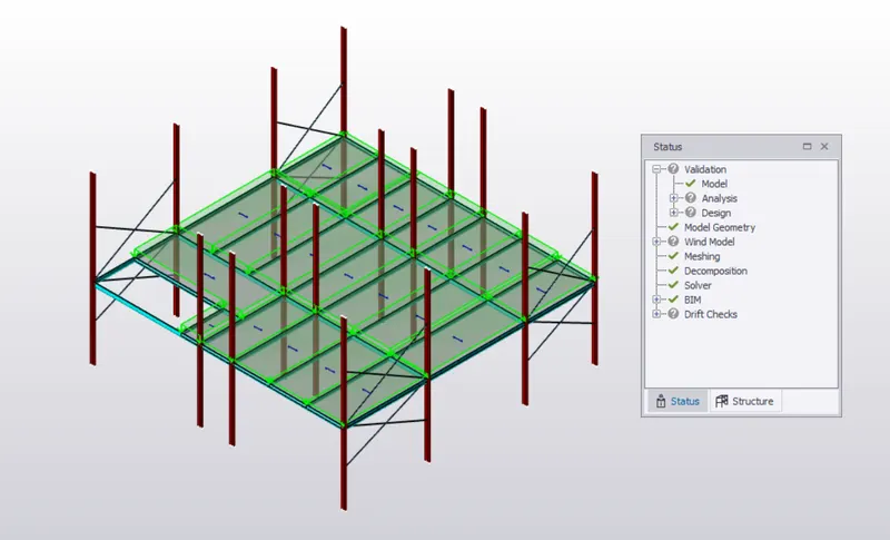
iii. Flat Roof:
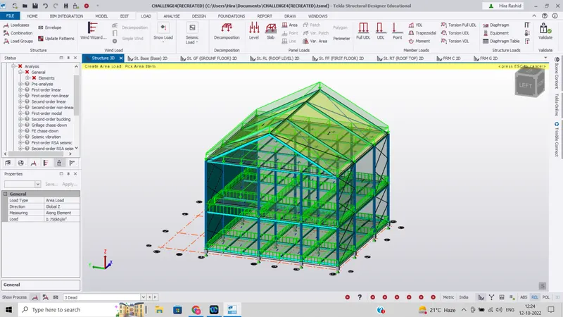
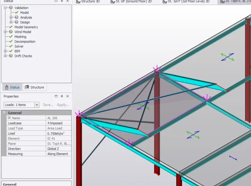
- Here Roof Flat Floor Are Access Not Povided so we take the Live Load: 0.75 KN/m2 From the (IS-875 (PART 1), Table 1)
- Above the same procedure to be used aplly for live load of Flat Roof
- Under the Load Tab, Select the Area Load for Applying Live Load
- Then select to drag down Select : 4 Imposed
- Live Load is:0.7 5N/m2
- Under the Area Load We need to select the Load type is: Area Load
- Direction: Global z
- Measuring: Along Elements
- Load : 0.75 KN/m2
- Now Pick Area Item the colour of the Floo r is changing
Properties :
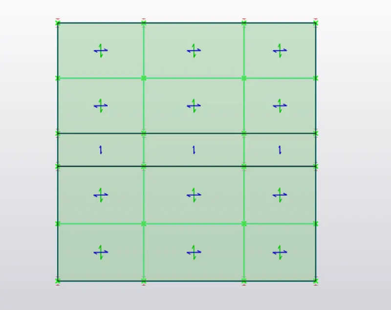
Validate:
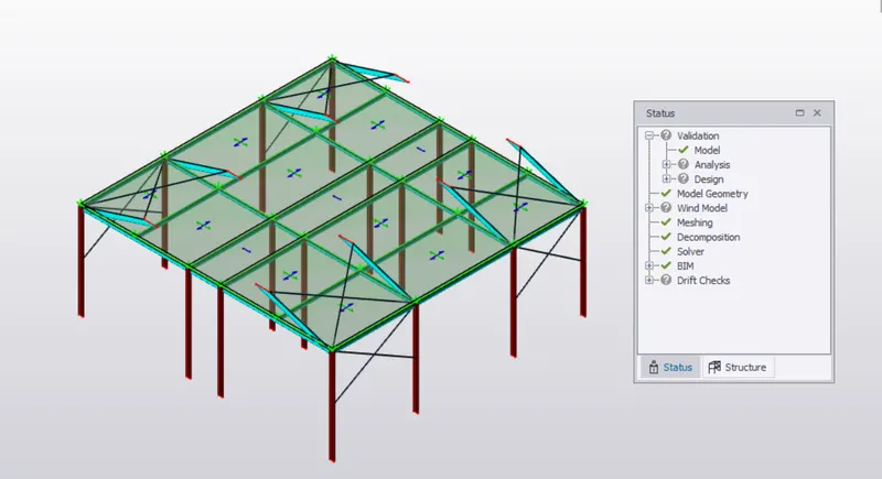
iv. Rafter Load:
- Access Not Provided Except Fro Mantenance
- Under the Load Tab, Select the Area Load for Applying Live Load
- Then select to drag down Select : 4 Imposed
- Live Load is:0.75N/m2
- Under the Area Load We need to select the Load type is: Area Load
- Direction: Global z
- Measuring: Along Elements
- Load : 0.75 KN/m2
- Now Pick Area Item the colour of the Floor is changing
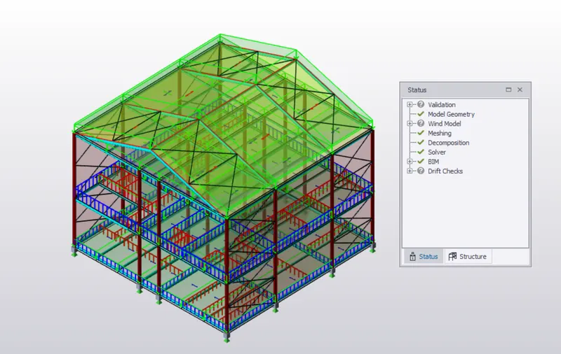
RESULT:
Question-3
Aim: To Generate a calculation for 5T crane loading based on following inputs
Procedure:
Load Calculation:
Given:
- Centre to Centre of wheel = 10m
- Weight of crab = 40 KN
- Number of wheels = 4
- Wheel base = 2m
- Crane Capacity = 50 KN
- Weight of trolley = 10 KN
- Minimum Hook Approach = 1m
Maximum Point Load on crane =Crane capacity + Weight of the Trolly
= 50+10
= 6o KN
UDL = Self weight of crane/Distance between rails
= 2.89 KN/m
Moment at A:
∑Ma=0
= 60x1-RBx14 + 2.89x14x14/2=0
4 RB = 60+283.22
RB = 24.52KN
∑Fy = 0
RA+RB-60-2.89x14 =0
RA = 60+2.89x14-RB
RB = 75.94 KN
Now Let Assume Self weight of Gantry Girder = 1.2 kn/m
Self weight of rail section = 0.3 KN/M
Total Self weight = 1.5 KN/m
Factor Load = 1.5x1.5
= 2.25 KN/m
Now Load on Each Wheel = 75.94/2 KN
= 37.97 KN
Factor Load = 1.5x37.97 =56.955 KN
= 57 KN
Moment at C:
∑Mc = 0
RDx6 = 2.25x6x6/2 + 57x4.5 + 57x2.5
RD = 439.5 KN/6
= 73.25 KN
∑Iy = 0
RC + RD-57-57-2.25X6
RC + RD = 127.5 KN
RC = 127.5-73.25
= 57.25 KN
Moment On Front Wheel
RD = 2.25x1.5x1.5/2
= 2.53 KN
Moment On Front Wheel
RC = 2.25x2.5x2.5/2
= 7.0 KN
Maximum Shear Force:
∑Mf = 0
REx6-57x6-57x4-2.25x6x6/2 = 0
RE = 101.75 KN
Impact Load:
10% Of Wheel Load = 0.1x101.75
= 10.175 KN
V = wl/2 = 1.5x6/2
= 4.5 KN
Maximum Shear force = 4.5 + 10.175 + 101.75
= 116.425 KN
Lateral Load Analysis = 5% of Total Weight
= 5/10 x 60
= 3 KN
RESULT:
- calculation of 5T crane loading is done