Creating a Floor plan, Footing detail and Isometric view using AutoCad
Aim: To create a floor plan,footing detail and isometric view using AutoCAD
Introduction:The sketching of these assignments make us get in touch with the various tools in AutoCAD like rectangle,polylines,isometric views,snap mode,offset mode,copy,move and ortho mode.Texts is also used to specify the particular rooms and objects.
Objective1:To draw the cross section of load bearing wall over spreaded footing
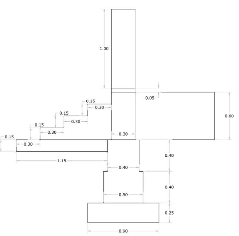
Procedure:
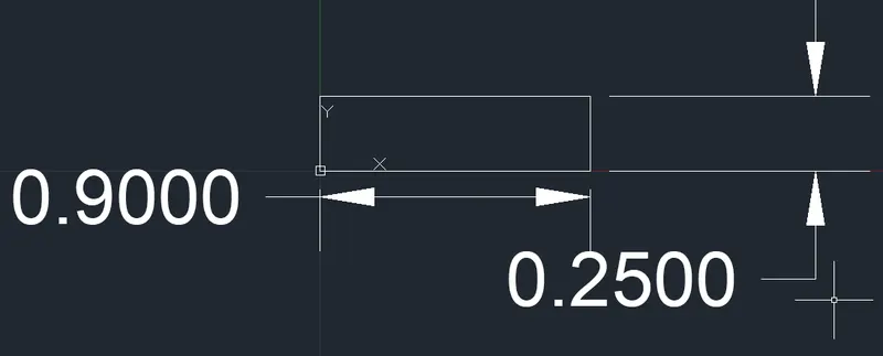
Type rec in the command line and press enter
Specify the first corner of the rectangle
Enter the length 0.90
Enter the width 0.25
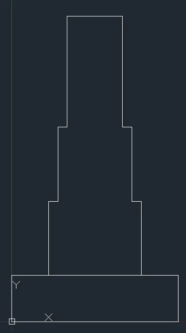
Type L in the command line and press enter
Now specify a point @0,0.25
Enter next point @.20,0
Enter next point @0,.40
Enter next point @.05,0
Enter next point @0,.40
Enter next point @0.05,0
Enter next point @0,.6
Enter next point @.3,0
Enter next point @0,-.6
Enter next point @.05,0
Enter next point @0,-.4
Enter next point @.05,0
Enter next point @0,-.4
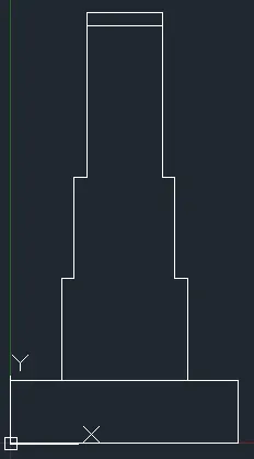
Now specify a point at the top left of the footing
Specify the next point @0,.05
Enter next point @.30,0
Enter next point @0,-0.05
Now specifying the point on the top left
Enter next point @0,1
Enter next point @.30,0
Enter next point @0,-1
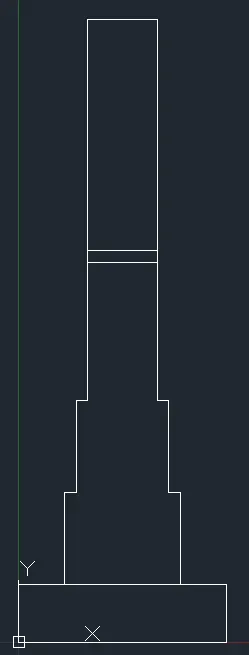
Specify the point at the top left of spread footing
Enter next point @-.30,0
Enter next point @-.05,0
Enter next point @-1.115,0
Enter next point @0,-.15
Enter next point @1.15,0
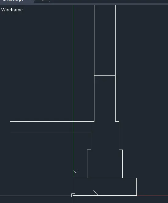
Now on this same figure specify the point on top left and enter @.30,0
Enter next point @0,.15
Enter next point @.30,0
Enter next point @0,.15
Enter next point @.30,0
Enter next point @0,.15
Enter next point @.30,0
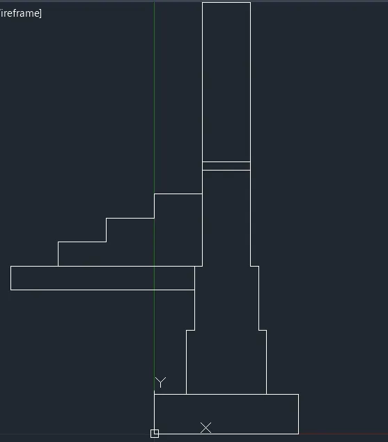
Specify the start point
Enter next point @1,0
Enter next point @0,-.6
Enter next point @-.95,0
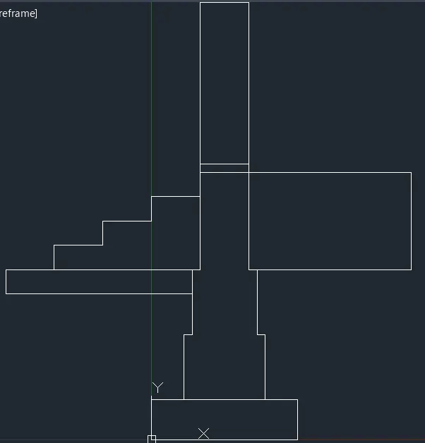
Type dim in the command box and specify the points for the dimensions
Resullt:
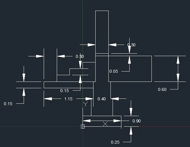
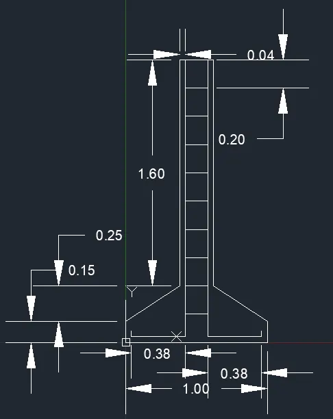
Objective2: Cross section of isolated footing
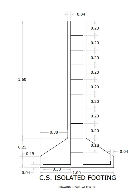
Procedure:
Type rec in the command box and press enter
Specify the first corner of the rectangle
Enter the length 1
Enter the width .40
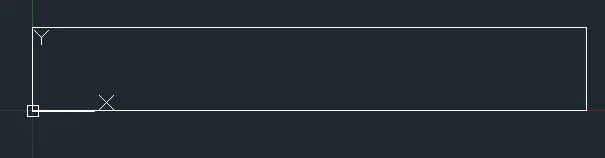
Type CHA in the command line and press enter
Specify the first chamfer distance .25
Specify the second chamfer distance .38
Select the first and second line to create chamfer
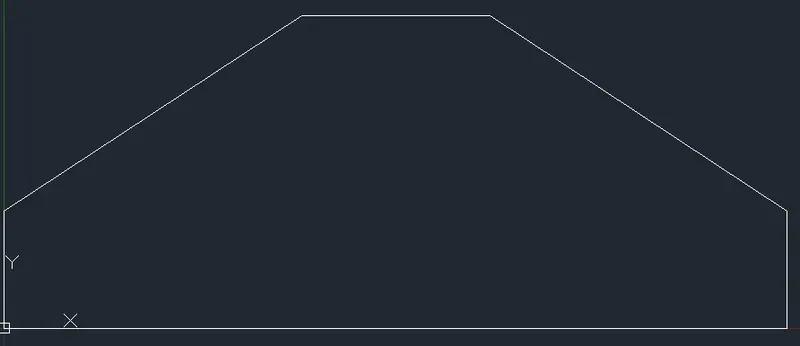
Type TRIM and trim out the top most line
Type line in the command line and press enter
Specify the point on the top left
Enter next point @0,1.60
Enter next point @.24,0
Enter next point @0,-1.6
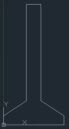
Type line in the command box and press enter
Specify the point on the top left @0.04,0
Enter next point @0,-1.96
Enter next point @-.38,0
Enter next point @0,.04
Now specifying point on the top [email protected],0
Enter next point @0,-1.96
Enter next point @.38,0
Enter next point @0,.04
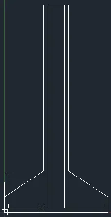
Type line in the command box and press enter
Specify a point on the top most line
Enter next point @.12,0
Type O or Offset in the command box and press enter
Specify the value of offset distance .2
select the object and offset will be created
Move the cursor till the requirement is met.
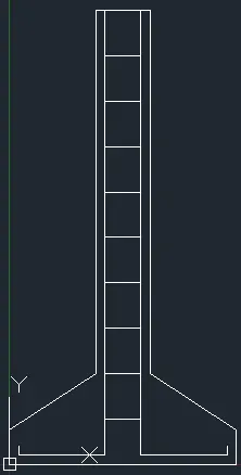
Type dim in the command box and specify the points for the dimensions
Resullt:
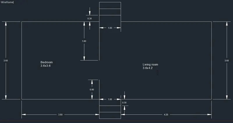
Objective3:Line Diagram of a bedroom and living room
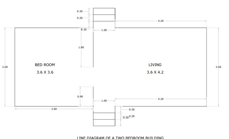
Procedure:
Type L in the command box and press enter
Specify a starting point
Enter next point @0,1.8
Enter next point @-3.6,0
Enter next point @0,-3.6
Enter next point @3.6,0
Enter next point @1,0
Enter next point @4.20,0
Enter next point @0,3.60
Enter next point @-4.2,0
Enter next point @-1,0

Deleting the two lines as per drawing

Type PL in the command box and press enter
Specify the first point of the polyline i.e upper region where we deleted the line
Enter next point @0,.3
Enter next point @1,0
Enter next point @0,-.3
Type CO in the command line and taking the base point paste 2 times
The steps done above are to be done in the downward region
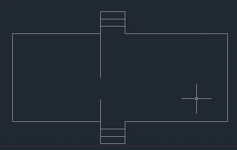
Type dim in the command box and specify the points for the dimensions
Resullt:
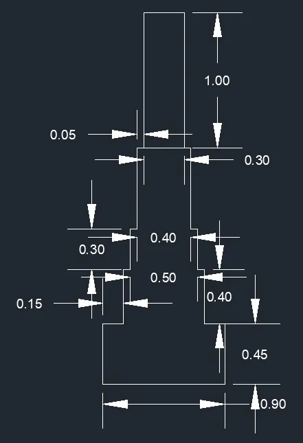
Objective4: Cross section of load bearing wall showing foundation details
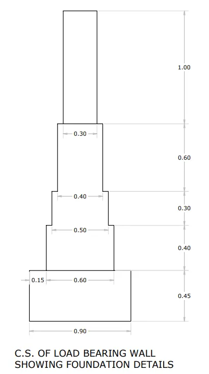
Procedure:
Type L in the command box and press enter
Specify a point 0,0
Enter next point @0,.45
Enter next point @.15,0
Enter next point @0,.40
Enter next point @.05,0
Enter next point @0,.30
Enter next point @.05,0
Enter next point @0,.6
Enter next point @.05,0
Enter next point @0,1
Enter next point @.30,0
Enter next point @0,-1
Enter next point @.05,0
Enter next point @0,-.6
Enter next point @.05,0
Enter next point @0,-.3
Enter next point @.05,0
Enter next point @0,-.3
Enter next point @.05,0
Enter next point @0,-.4
Enter next point @.15,0
Enter next point @0,-.45
Enter next point @-.9,0
Type dim in the command box and specify the points for the dimensions
Resullt:
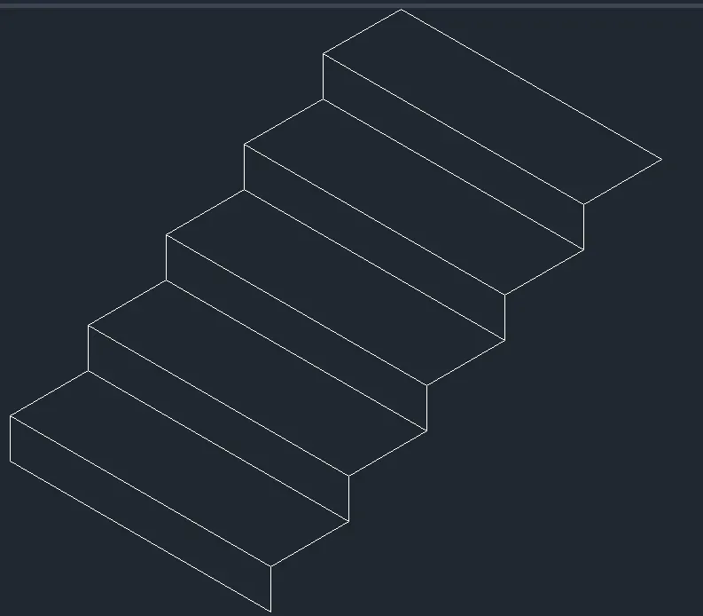
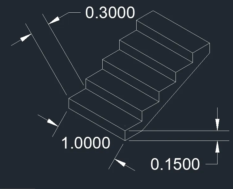
Objective 5: Isometric view of steps
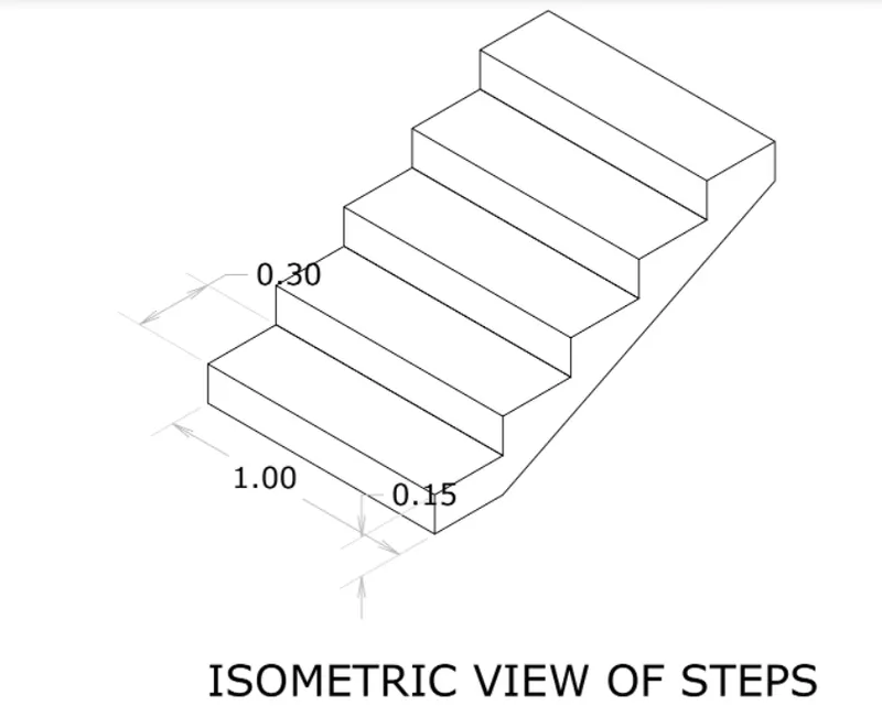
Procedure:
Type DS in the command box and press enter
Tick the snap and grid mode on
Tick on the isometric snap in snap type
Now we have the isometric view on our screen
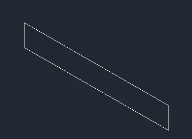
Type PL in the command box and press enter
Specify a starting point
Take isoplane left
Specify the next point as 1
Now take isoplane right
Specify the next point .15
Specify the next point 1
Specify the next point .15
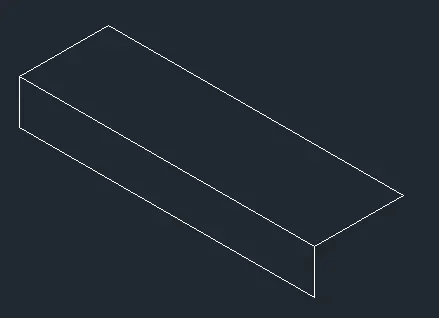
Type PL in the command box and press enter
Specify a point at the top right corner
Take Isoplane top
Specify the point .30
Enter the next point 1
Enter the next point .3
Type CO in the command box and press enter
Select the complete steps and press enter
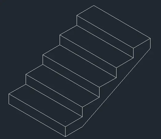
Type L in the command box and press enter
Specify the top right corner
Take isoplane right
Specify the next point .15
Type L in the command box and press enter
Specify the bottom right corner
Take isoplane right
Specify the next point .30
Type L in the command box and press enter
Join the points
Type dim in the command box and specify the points for the dimensions
Result:
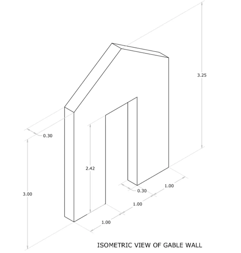
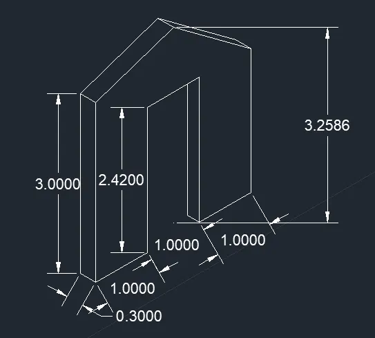
Objective6:Isometric view of gable wall
Procedure:
Type DS in the command box and press enter
Tick the snap and grid mode on
Tick on the isometric snap in snap type
Now we have the isometric view on our screen
Type PL in the command box and press enter
Specify a starting point
Take isoplane left
Specify the next point .30
Specify the next point 3
Specify the next point .30
Specify the next point 3
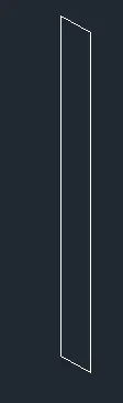
Type L in the command box and press enter
Specify the starting point as the bottom right point
Take isoplane top
Specify the next point1
Specify the next point1
Specify the next point1
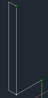
Deleting one line as per drawing
Type L in the command box and press enter
Specify the starting point at the starting of the deleted line
Take isoplane right
Specify the next point as 2.42
Take isoplane top
Specify the point 1
Specify the next point 2.42
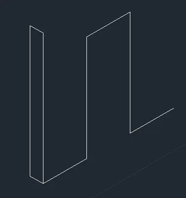
Type L in the command line and press enter
Specify the start point
Take isoplane left
Specify the next point .3
Take isoplane right
Specify the next point 2.42
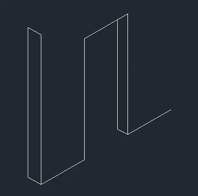
Type L in the command line and press enter
Specifying the starting point
Take isoplane top
Specify the next point 1.5
Take isoplane right
Specify the next point 3.25
Type L in the command line and press enter
Take isoplane left
Specify the next point .3
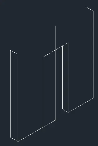
Specifying points as per drawing
Deleting the extra lines
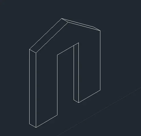
Type dim in the command box and specify the points for the dimensions
Resullt:
Conclusion:
Created a floor plan,footing detail and isometric view using AutoCAD and had good understanding of tools like rectangle,polylines,isometric views,snap mode,offset mode,copy,move and ortho mode.