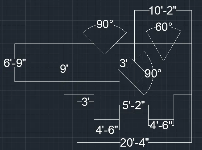
Drafting of various geometries using Chamfer, Fillet tool in AutoCad
Aim: Drafting of various geometries using chamfer,fillet tool in AutoCAD
Introduction: AutoCAD consists of a number of drawing and modification tools.Among the modification toolss are chamfer,fillet,offset,object snap,rotate,copy,move,mirror,trim,entend and join
Chamfer: A chamfer is an angled line that meets the endpoints of two straight 2D objects.Its a sloped transition between two surfaces or adjacent faces on a 3D solid.We type CHA for this tool in command bar
Fillet: The fillet command is used to create rounded edges between the adjacent lines and faces in 2D and 3D. It is also used to connect two tangent arcs in 2D.Type F
Offest:Creates concentric circles, parallel lines, and parallel curves.Type O in the command bar
Object Snap: Object snaps provide a way to specify precise locations on objects whenever we are prompted for a point within a command.Type OS in the command bar
Rotate: Rotates objects around a base point. Wcan rotate selected objects around a base point to an absolute angle.We type RO and rotate the object accordingly
Copy: Copies objects a specified distance in a specified direction.We can enter C in the command line
Move: Moves objects a specified distance in a specified direction.Type M in the command bar
Mirror: Creates a mirrored copy of selected objects. Wcan create objects that represent half of a drawing, select them, and mirror them across a specified line to create the other half. Type MI in the command bar
Trim: Trims objects to meet the edges of other objects. Type TR in the command bar.
Extent: Extends objects to meet the edges of other objects.It extend objects, first select the boundaries. Then press Enter and select the objects that you want to extend. To use all objects as boundaries, press Enter at the first Select Objects prompt.
Join: Joins the endpoints of linear and curved objects to create a single object. It combines a series of finite linear and open curved objects at their common endpoints to create a single 2D or 3D object. The type of object that results depends on the types of objects selected, the type of object selected first, and whether the objects are coplanar.
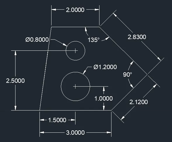
Objective 1: Draft the given geometry using decimal unit system:
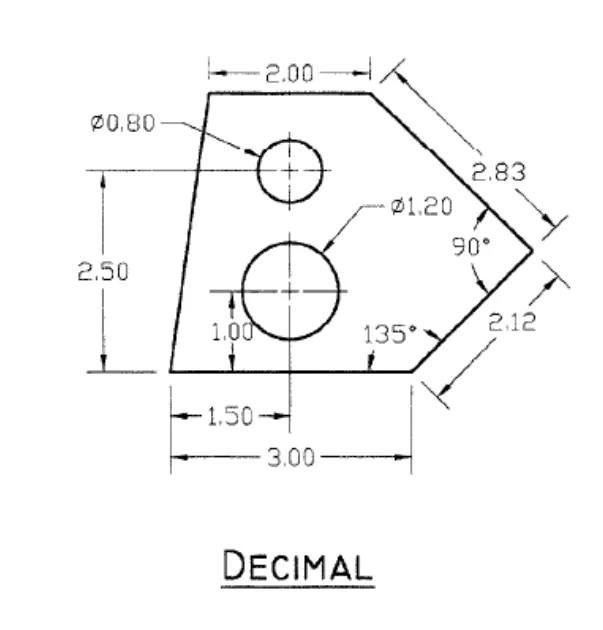
Procedure:
STEP 1:
Enter UNITS command in the command bar.
In the Drawing units dialog box select DECIMAL and type 0.00 in the precision and METERS in insertion scale.
Click on OK
STEP 2:
Select the line tool by entering L in the command tab
Specify the first point as 0,0 in the command line
Specify the coordinate of the next point as @3.00<0 in the command line
Specify the coordinate of the next point as @2.12<45
Specify the coordinate of the next point as @2.83<135
Specify the coordinate of the next point as @-2<0
Click close on the command line.

STEP3:
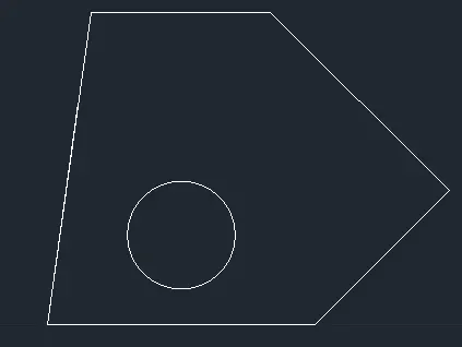
Select the circle tool by entering CIR in command tab
Specify the coordinate of the next point as 1.5,1
Specify the dia option in the command line and specify the dia of circle as 1.2
STEP 4:
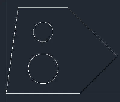
Select the circle tool by entering CIR in command tab
Specify the coordinate of the next point as 1.5,2.5
Specify the dia option in the command line and specify the dia of circle as 0.80
STEP 5:
Enter DIMSTY in the command line
Click on the modify tab
Change the text height and whatsoever needed
Click OK
Now type DIM and click on points of whome the dimensions are needed.
For angle measurements type DIMANGULAR and select the two lines between which we need to find angle.
RESULT:
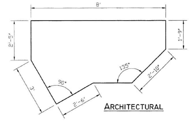
Objective2: Draft the given geometry using Architectural unit system
STEP1:
Enter UNITS command in the command bar.
In the Drawing units dialog box select ARCHITECTURAL and type 0'-0" in the precision and INCHES in insertion scale.
Click on OK
STEP2:
Select the line tool by entering L in the command tab
Specify the first point as 10,10 in the command line
Specify the coordinate of the next point as @2'-10"<45 in the command line
Specify the coordinate of the next point as @0,1'-9"
Specify the coordinate of the next point as @-8',0
Specify the coordinate of the next point as @0,-2'5"
Specify the coordinate of the next point as @3'<300
Specify the coordinate of the next point as @2'6"<30
Click close on the command line.
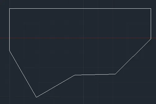
Enter DIMSTY in the command line
Click on the modify tab
Change the text height and whatsoever needed
Click OK
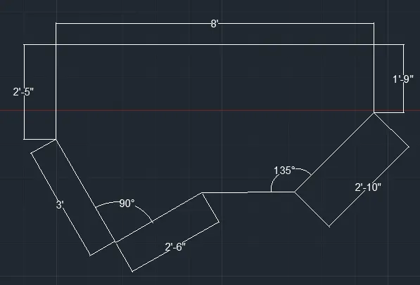
Now type DIM and click on points of whome the dimensions are needed.
For angle measurements type DIMANGULAR and select the two lines between which we need to find angle.
RESULT:
Objective3: Draft the given geometry using enginerring unit system
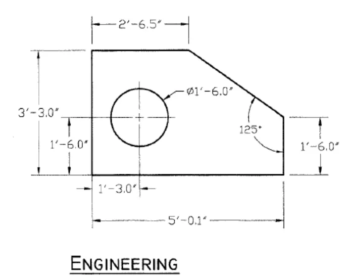
STEP1:
Enter UNITS command in the command bar.
In the Drawing units dialog box select ENGINEERING and type 0'-0.0" in the precision and INCHES in insertion scale.
Click on OK
STEP2:
Select the line tool by entering L in the command tab
Specify the first point as 0'0.00'', 0'0.00'' in the command line
Specify the coordinate of the next point as @5'0.1'', 0'0.0" in the command line
Specify the coordinate of the next point as @0'0.0",3'3.0"
Specify the coordinate of the next point as @-5'0.1",0'0.0"
Click close on the command line.

STEP3:
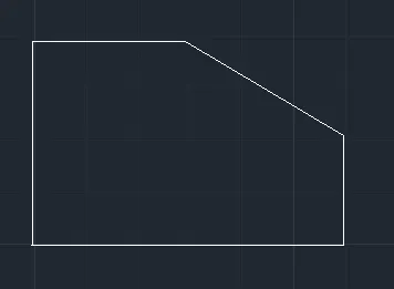
Type CHA in the command box
Select the ANGLE option in the command line
Specify the chamfer length 1'6.0"
Specify the angle as 125
Select the first chamfer line
Select the DISTANCE options in the command bar
Specify the first chamfer distance 1'9.0''
Specify the second chamfer distance 2'5.6''
Then select the second line
STEP4:
Select the circle tool by entering CIR in command tab
Specify the coordinate of the next point as 1'3.0'',1'6"
Specify the dia option in the command line and specify the dia of circle as 1'6"
STEP5:
Enter DIMSTY in the command line
Click on the modify tab
Change the text height and whatsoever needed
Click OK
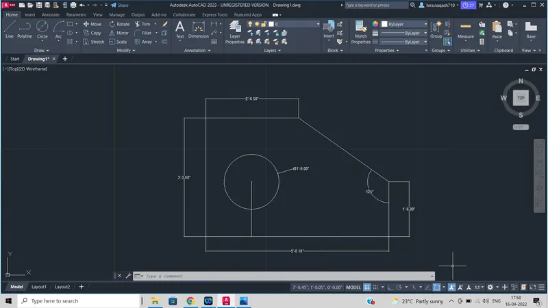
Now type DIM and click on points of whome the dimensions are needed.
For angle measurements type DIMANGULAR and select the two lines between which we need to find angle.
RESULT:
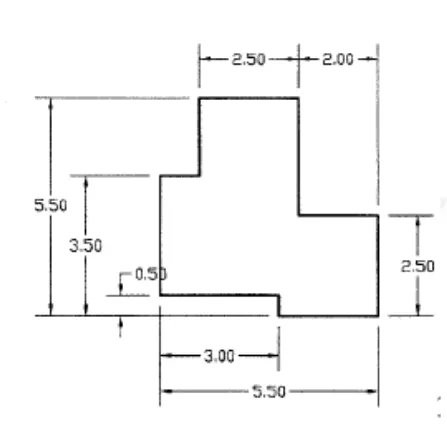
OBJECTIVE 4:
STEP1:
Enter UNITS command in the command bar.
In the Drawing units dialog box select DECIMAL and type 0.00 in the precision and METERS in insertion scale.
Click on OK
STEP 2:
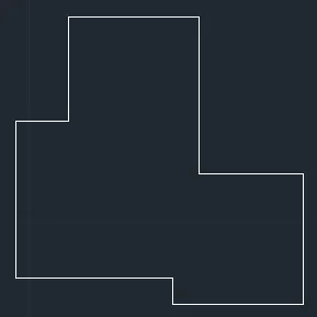
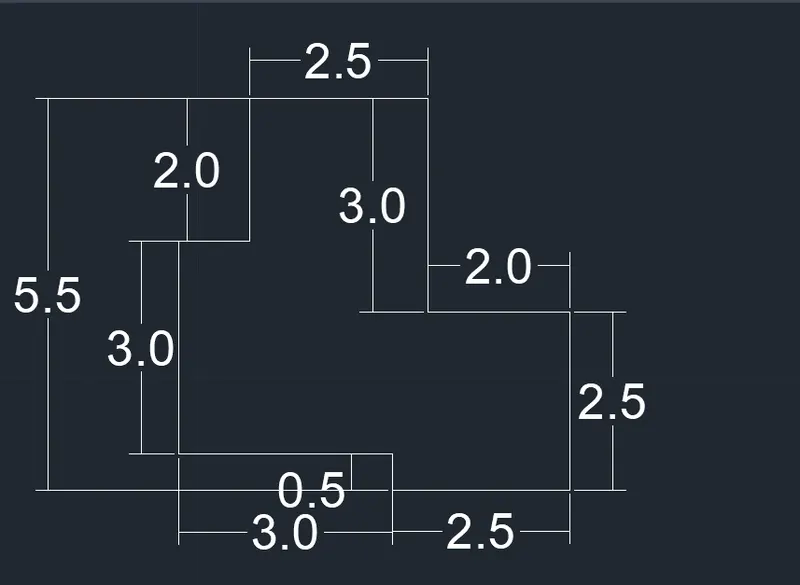
Select the line tool by entering L in the command tab
Specify the first point as 0,0 in the command line
Specify the coordinate of the next point as @3,0 in the command line
Specify the coordinate of the next point as @0,-5
Specify the coordinate of the next point as @2.5,0
Specify the coordinate of the next point as @0,2.5
Specify the coordinate of the next point as @-2,0
Specify the coordinate of the next point as @0,3
Specify the coordinate of the next point as @-2.5,0
Specify the coordinate of the next point as @0,-2
Specify the coordinate of the next point as @-1,0
Click close on the command line.
STEP3:
Enter DIMSTY in the command line
Click on the modify tab
Change the text height and whatsoever needed
Click OK
Now type DIM and click on points of whome the dimensions are needed.
For angle measurements type DIMANGULAR and select the two lines between which we need to find angle.
RESULT
Objective5: Draft the geometry using AutoCAD tool
STEP1:
Enter UNITS command in the command bar.
In the Drawing units dialog box select DECIMAL and type 0.00 in the precision and METERS in insertion scale.
Click on OK
STEP 2:
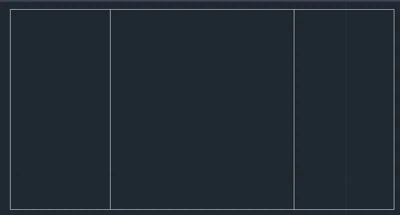
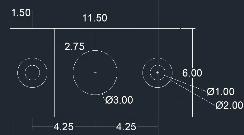
Select the line tool by entering L in the command tab
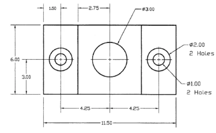
Specify the first point as 0,0 in the command line
Specify the coordinate of the next point as @11.5,0 in the command line
Specify the coordinate of the next point as @0,-6
Specify the coordinate of the next point as @-11.5,0
Click close on the command line.
STEP3:
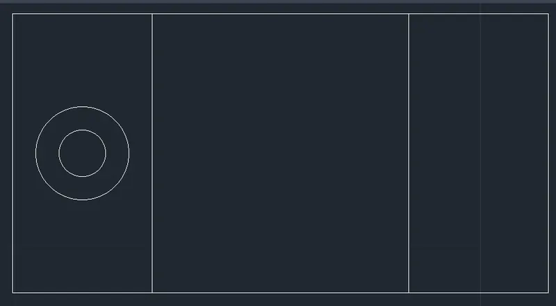
Type O in the command bar to introduce offset tool
Enter 3 as offset distance in the command bar
Select the left vertical line
Repeat for the right vertical line
STEP4:
Select the circle tool by entering CIR in command tab
Specify the coordinate of the next point as 1.5,3
Specify the dia option in the command line and specify the dia of circle as 2
Type O in the command bar to introduce offset tool
Enter .5 as offset distance in the command bar
STEP5:
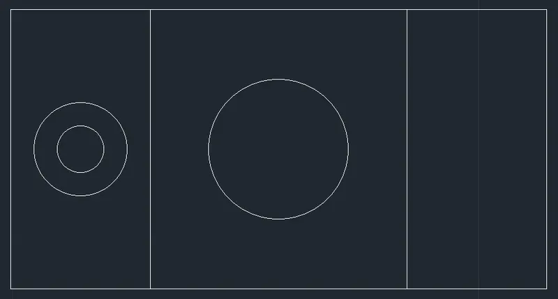
Select the circle tool by entering CIR in command tab
Specify the coordinate of the next point as 5.75,3
Specify the dia option in the command line and specify the dia of circle as 3
STEP 6:
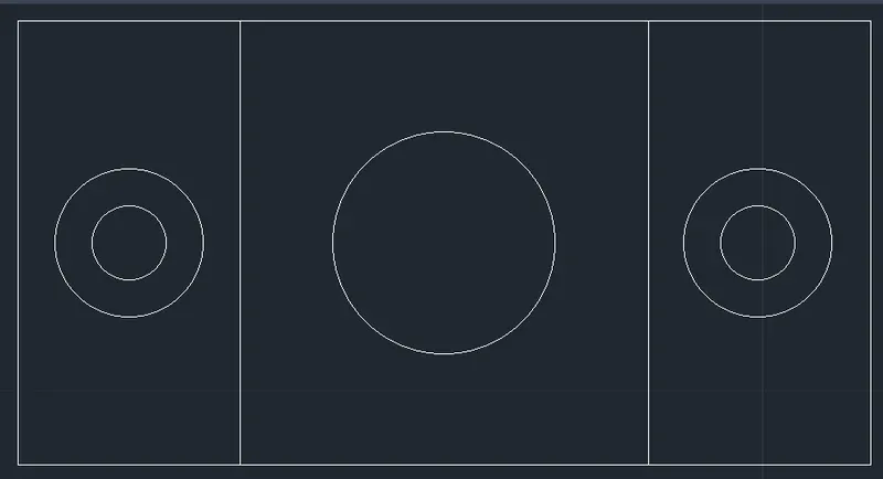
Select the circle tool by entering CIR in command tab
Specify the coordinate of the next point as 1.5,3
Specify the dia option in the command line and specify the dia of circle as 2
Type O in the command bar to introduce offset tool
Enter .5 as offset distance in the command bar
STEP 7
Enter DIMSTY in the command line
Click on the modify tab
Change the text height and whatsoever needed
Click OK
Now type DIM and click on points of whome the dimensions are needed.
For angle measurements type DIMANGULAR and select the two lines between which we need to find angle.
RESULT
Objective 6: Drafting the geometry using AutoCAD
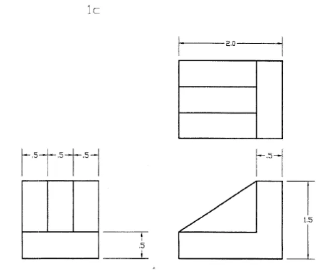
STEP1:
Enter UNITS command in the command bar.
In the Drawing units dialog box select DECIMAL and type 0.00 in the precision and METERS in insertion scale.
Click on OK
STEP 2:
Select the line tool by entering L in the command tab
Specify the first point as 4.5,2.5 in the command line
Specify the coordinate of the next point as @1.5,0 in the command line
Specify the coordinate of the next point as @0,1.5
Specify the coordinate of the next point as @-1.5,0
Click close on the command line.
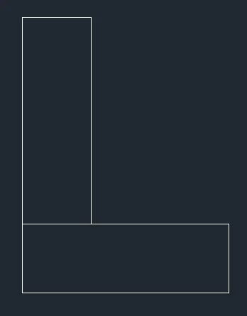
Type O in the command bar to introduce offset tool
Enter .5 as offset distance in the command ba
Type TR in the command box
Press enter
Trim the excessive lines as per drawing
STEP3:
Enter DIMSTY in the command line
Click on the modify tab
Change the text height and whatsoever needed
Click OK
RESULT
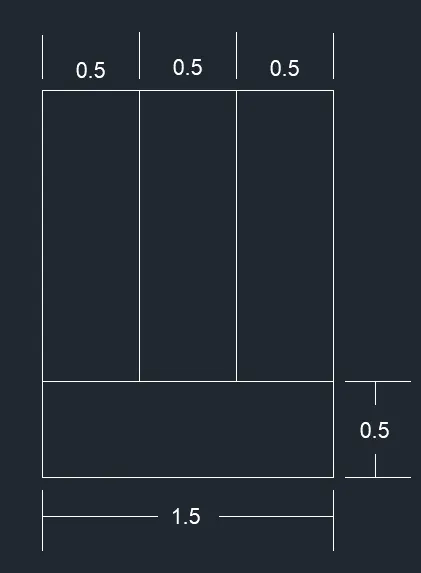
b.
STEP1:
Enter UNITS command in the command bar.
In the Drawing units dialog box select DECIMAL and type 0.00 in the precision and METERS in insertion scale.
Click on OK
STEP 2:
Select the line tool by entering L in the command tab
Specify the first point as 4.5,2.5 in the command line
Specify the coordinate of the next point as @2,0 in the command line
Specify the coordinate of the next point as @0,2
Specify the coordinate of the next point as @-2,0
Click close on the command line.
Type O in the command bar to introduce offset tool
Enter .5 as offset distance in the command ba
Type TR in the command box
Press enter
Trim the excessive lines as per drawing
STEP3:
Enter DIMSTY in the command line
Click on the modify tab
Change the text height and whatsoever needed
Click OK
RESULT:
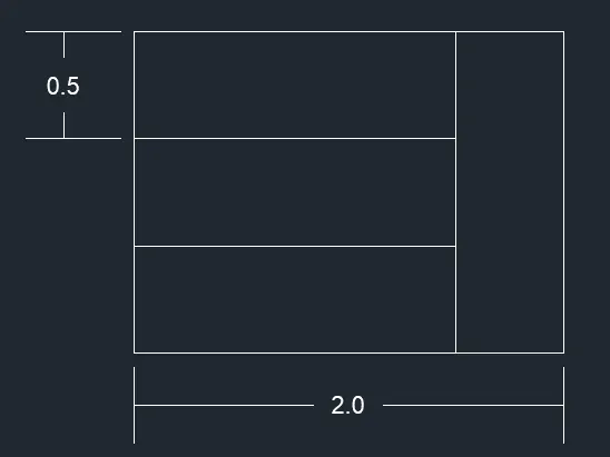
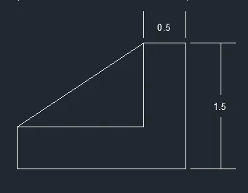
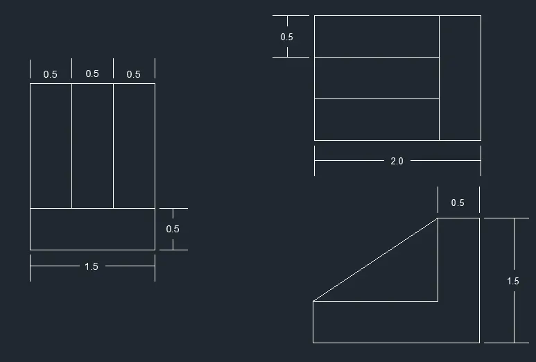
c. Type REC in the command box
Specify a point 20,20
Specify another point @0.5,-1.5
Type REC in the command box
At the bottom right end of the rectangle specify a point
Specify the other point -2,0.5
Join the ends
Type trim and trim the excess lines
Enter DIMSTY in the command line
Click on the modify tab
Change the text height and whatsoever needed
Click OK
Now type DIM and click on points of whome the dimensions are needed.
For angle measurements type DIMANGULAR and select the two lines between which we need to find angle.
RESULT:
Objective7: Draft geometry 7
STEP1:
Enter UNITS command in the command bar.
In the Drawing units dialog box select DECIMAL and type 0.00 in the precision and METERS in insertion scale.
Click on OK
STEP 2:
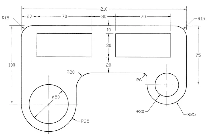
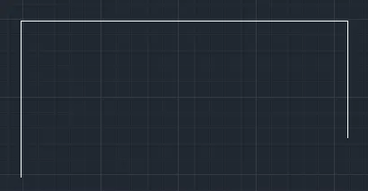
Select the line tool by entering L in the command tab
Specify the first point as 0,0 in the command line
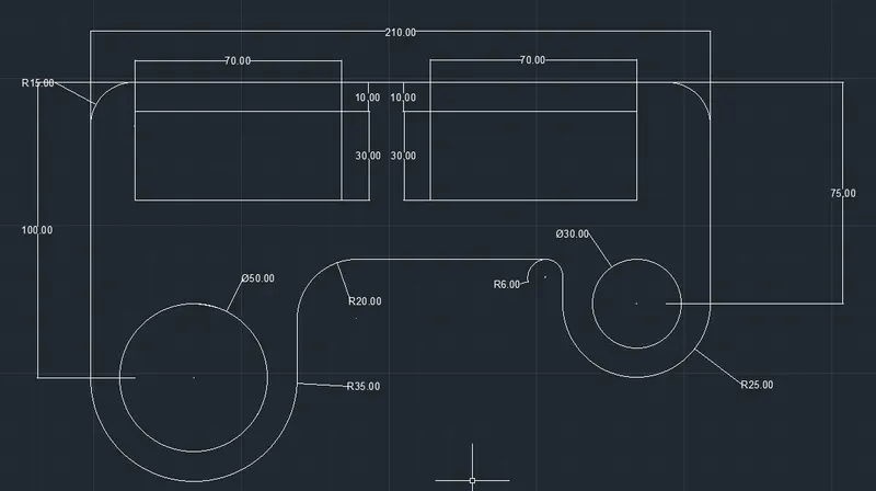
Specify the coordinate of the next point as @0,100 in the command line
Specify the coordinate of the next point as @210,0
Specify the coordinate of the next point as @0,-75
Click close on the command line.
STEP3:
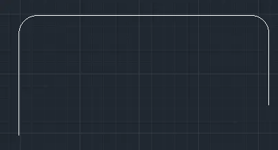
Type F in the command bar for fillet option
Select the line of length 100 units
Click on the radius option
Specify the radius 15
Select the second line as 210
Again select the fillet tool
Select the length 75
specify the radius 15
STEP4
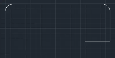
Select the line tool by entering L in the command tab
Specify the first point as 0,0 in the command line
Specify the coordinate of the next point as @70,0 in the command line
Specify the coordinate of the next point as @210,25
Specify the coordinate of the next point as @-50,0
Click close on the command line.
STEP5:
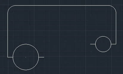
Select the circle tool by entering CIR in command tab
Specify the coordinate of the next point as 70,0
Specify the dia option in the command line and specify the dia of circle as 50
Select the circle tool by entering CIR in command tab
Specify the coordinate of the next point as -50,0
Specify the dia option in the command line and specify the dia of circle as 30
STEP6:
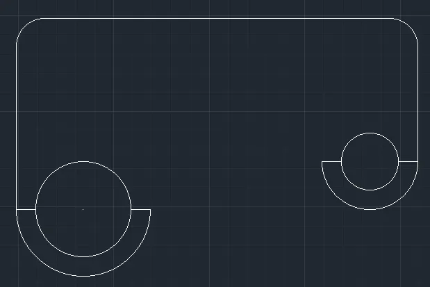
Select the ARC tool
Specify the first point of arc as the start point of the line of length 70 units
Select the end option
Specify the end point of arc as the end point of 70 units
Specify radius 35
Specify the first point of arc as the start point of the line of length 50 units
Select the end option
Specify the end point of arc as the end point of 50 units
Specify radius 25
Step 7
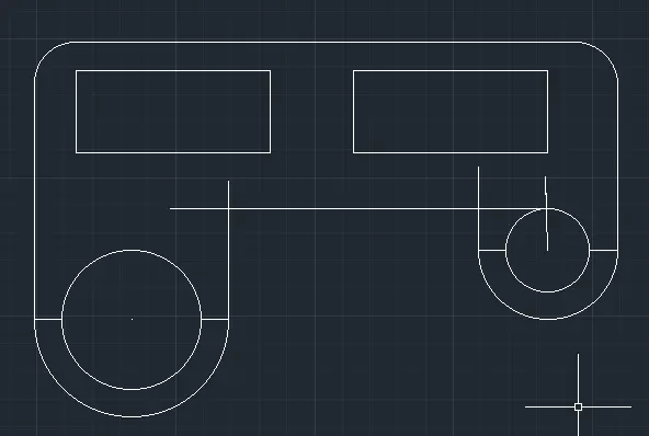
Type REC in the command box
Specify a point 20,60
Specify another point @70,30
Type MIRROR in the command tab
Select the rectangle
Press enter
Select the base point and select it at the distance of 30 at the end of span 70
Select the line tool by entering L in the command tab
Specify the first point as 0,-20 in the command line
STEP 8:
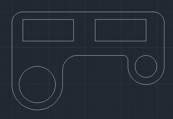
Type trim and trim the excess lines as per drawing
Type F in the command bar for fillet option
Select the line 210 and 100 on the left side and specify radius 15
Do the exact same thing on right side
Select the line extended from the arc
Click on the radius option
Specify the radius 20
Select the second line extending from arc
Again select the fillet tool
Specify the radius 6
STEP 9
Enter DIMSTY in the command line
Click on the modify tab
Change the text height and whatsoever needed
Click OK
Now type DIM and click on points of whome the dimensions are needed.
For angle measurements type DIMANGULAR and select the two lines between which we need to find angle.
RESULT:
Objective 8:
STEP1:
Enter UNITS command in the command bar.
In the Drawing units dialog box select DECIMAL and type 0.00 in the precision and METERS in insertion scale.
Click on OK
STEP 2:
Select the line tool by entering L in the command tab
Specify the first point as 5,5 in the command line
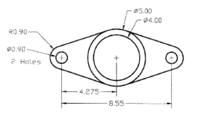
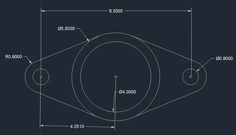
Specify the coordinate of the next point as @8.55,0 in the command line
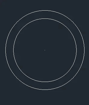
Select the circle tool by entering CIR in command tab
Specify the coordinate of the next point as mid point of the line drawn previously
Specify the dia option in the command line and specify the dia of circle as 5
Type O in the command bar to introduce offset tool
Enter .5 as offset distance in the command bar
Select the circle of dia 5 units
Click on inside of the circle
STEP 3:
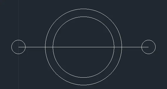
Select the circle tool by entering CIR in command tab
Specify the coordinate of the next point as 8.55,0
Specify the dia option in the command line and specify the dia of circle as 0.9
Do the exact same thing on the other extreme of the line
STEP 4:
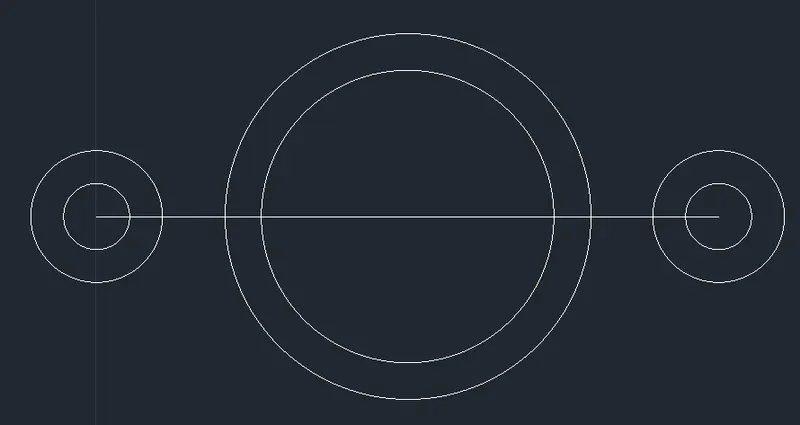
Select the circle tool by entering CIR in command tab
Specify the mid point of the circle on the left extreme
Specify the dia option in the command line and specify the radius of circle as 0.9
Select the circle tool by entering CIR in command tab
Specify the mid point of the circle on the right extreme
Specify the dia option in the command line and specify the radius of circle as 0.9
STEP 5
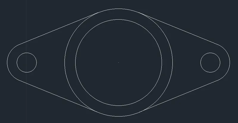
Enter ONSNAP in the command line
Turn on the tangent mode
Select the line tool
Draw a line joing the tangent points of the circle of rad .9 on the right side and the circle of dia 5
Repeat the procedure on the all four tangents
Select trim and remove the excess lines as per drawing
STEP 6:
Enter DIMSTY in the command line
Click on the modify tab
Change the text height and whatsoever needed
Click OK
Now type DIM and click on points of whome the dimensions are needed.
For angle measurements type DIMANGULAR and select the two lines between which we need to find angle.
RESULT:
OBJECTIVE 9:
STEP1:
Enter UNITS command in the command bar.
In the Drawing units dialog box select ARCHITECTURAL and type 0'-0" in the precision and INCHES in insertion scale.
Click on OK
STEP2:
Select the line tool by entering L in the command tab
Specify the first point as 10',10' in the command line
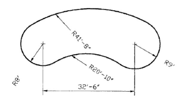
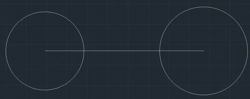
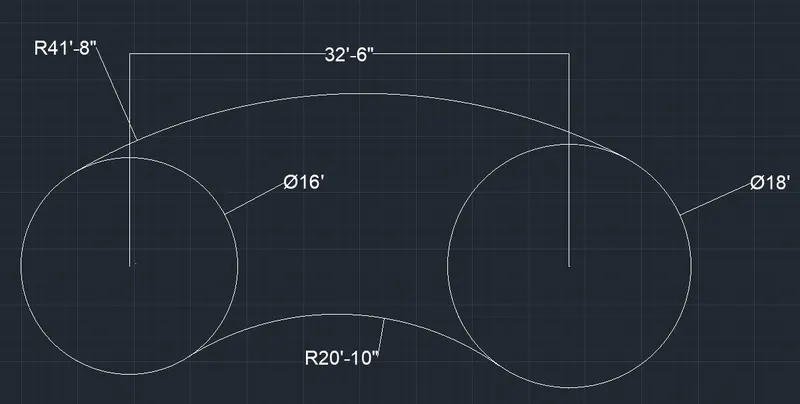
Specify the coordinate of the next point as @32'6",0'0" in the command line
Select the circle tool by entering CIR in command tab
Specify the center point of the circle as the start point of the line of length 32'6"
Specify the radius of circle as 9'
STEP 3:
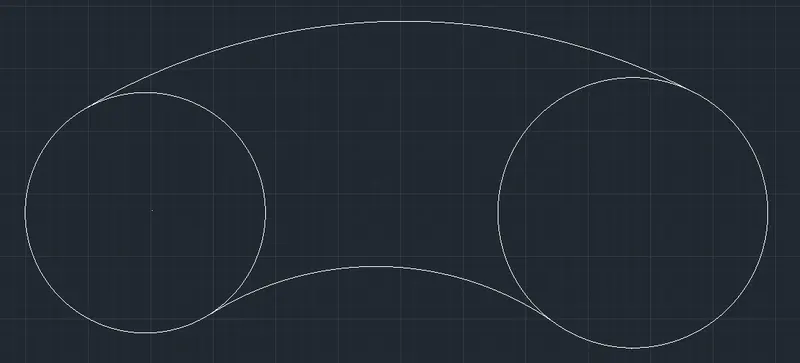
Select START END RADIUS arc and specify the first point at the tangent of first circle , end point at the tangent of the second circle and specify the radius as 41'-8"
Select the TAN TAN RADIUS in the circle option and specify the tangents of the both circles by turning on the snap mode
Specify the radius as 32'-6"
STEP 4
Enter DIMSTY in the command line
Click on the modify tab
Change the text height and whatsoever needed
Click OK
Now type DIM and click on points of whome the dimensions are needed.
For angle measurements type DIMANGULAR and select the two lines between which we need to find angle.
RESULT:
Objective 10:
STEP1:
Enter UNITS command in the command bar.
In the Drawing units dialog box select DECIMAL and type 0.00 in the precision and METERS in insertion scale.
Click on OK
STEP 2:
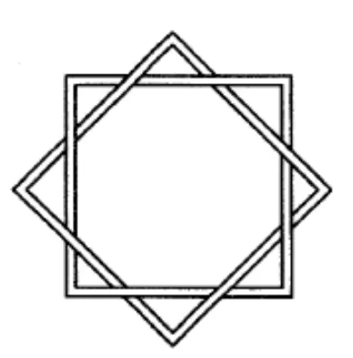
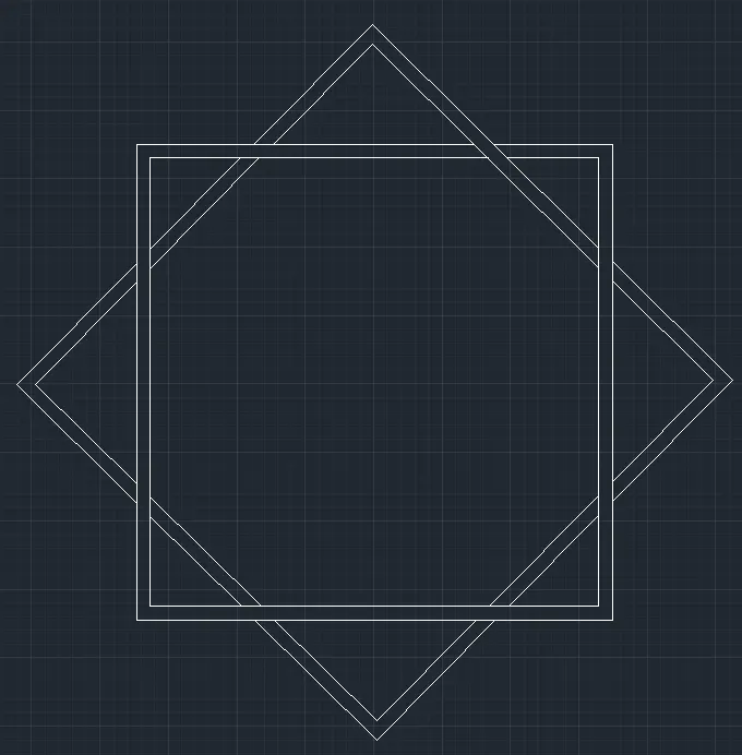
Select POLYGON and select the sides i.e 4 as a rhombus and specify the center
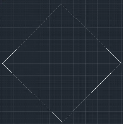
Select OFFSET and select the offset length
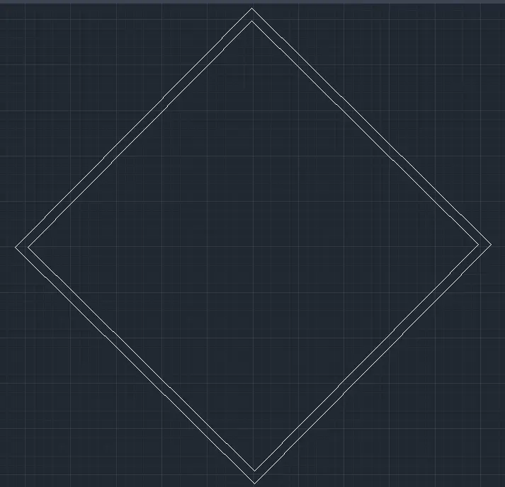
Select REC and with same dimensions draw a rectangle
Select OFFSET and select the offset length
Select trim and trim the excess lines
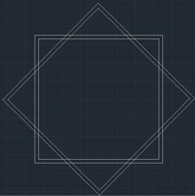
RESULT
OBJECTIVE 11:
STEP1:
Enter UNITS command in the command bar.
In the Drawing units dialog box select ENGINEERING and type 0'-0.0" in the precision and INCHES in insertion scale.
Click on OK
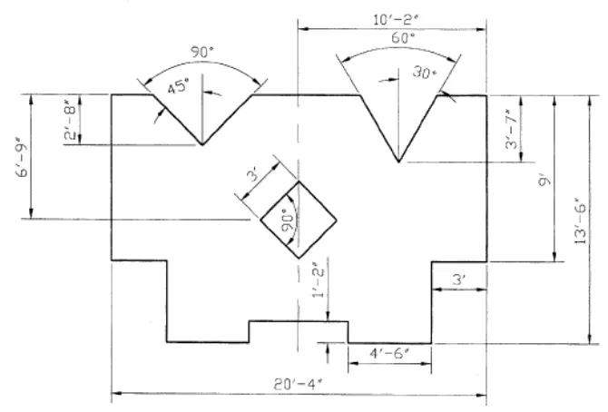
STEP2:
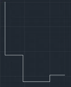
Type PLINE and specify a point arbitrarily
Specify the next point 9'<270
Specify the next point 3'<0
Specify the next point 4'-6"<270
Specify the next point 4'-6"<0
Specify the next point 1'-2"<90
Specify the next point 2'-4"<0
STEP 3:
Select MIRROR ,select the polyline
Pick the base point and enter on the next side
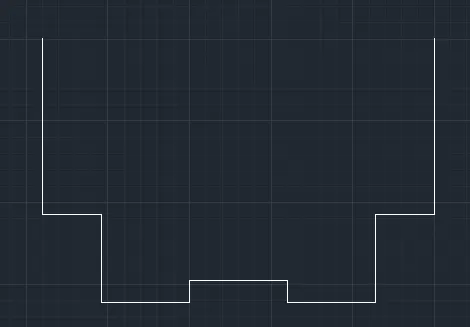
STEP 4:
Type L and specify the point on the top right end 3'<180
Specify the point @3'7"<240
Specify the point @3'7"<300
Type L and specify the point on the top left end 3'<180
Specify the point @2'8"<315
Specify the point @2'8"<45
Join the ends
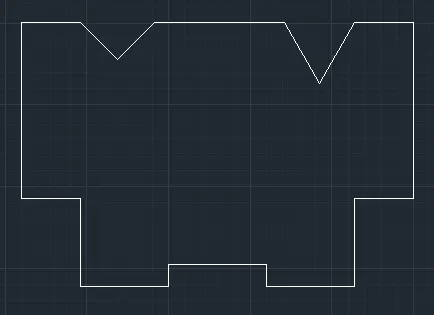
STEP 5:
Type L and specify the point on the top right end and drag to 10'-2"<180
Taking this point as a refrence connect it to the line below <270
Taking this bottom line as a refrence drag to 3'-4"<90
Type recatangle and specify a point at this end and other point @3',3'
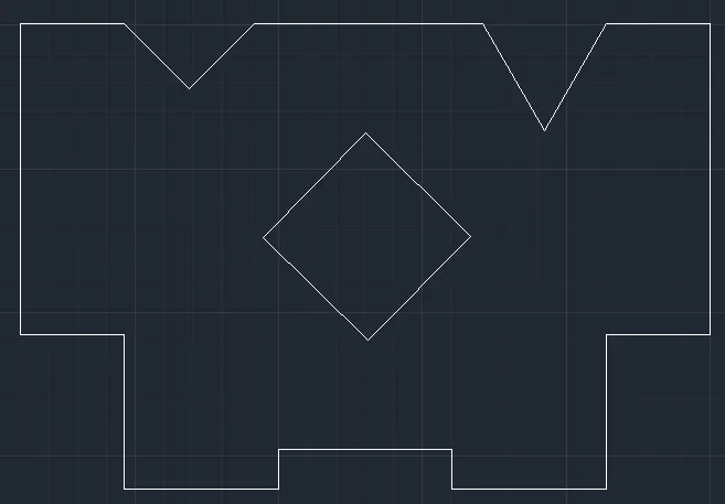
Enter DIMSTY in the command line
Click on the modify tab
Change the text height and whatsoever needed
Click OK
Now type DIM and click on points of whome the dimensions are needed.
For angle measurements type DIMANGULAR and select the two lines between which we need to find angle.
RESULT: