To Analysis and Design of Steel Structures using TSD
1)
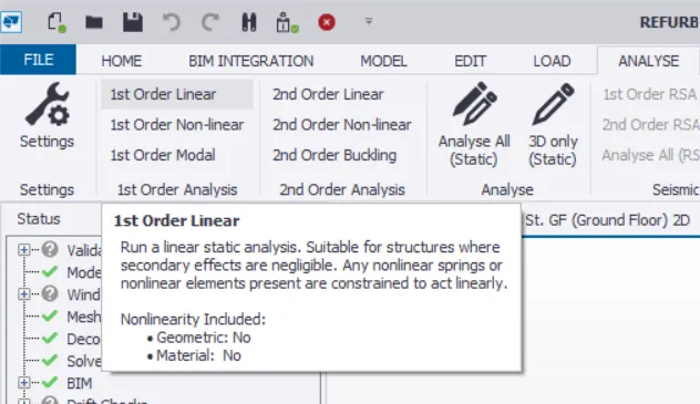
Initially,we go to desired model which is to be analyzed.Then we go to ANALYZE Tab>1st Order Linear option as the model is just a basic structure with basic loads.
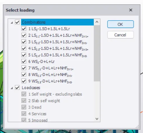
And then we select the required Loadcases and Combinations from the resultant tab,but on a general scale we do select everything for the point of safety.
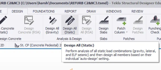
We then select all the members of the model by the window selection and then using the option of Design All(Static) we analyze all the members.
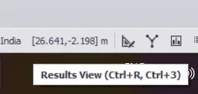
The we go to the Results View which is available at the bottom right of the screen.
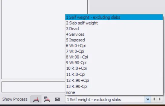
Where then we select the require load case or combination from the bottom left of the screen.
Then,we select the required load from the Results,where then required diagram is displayed.
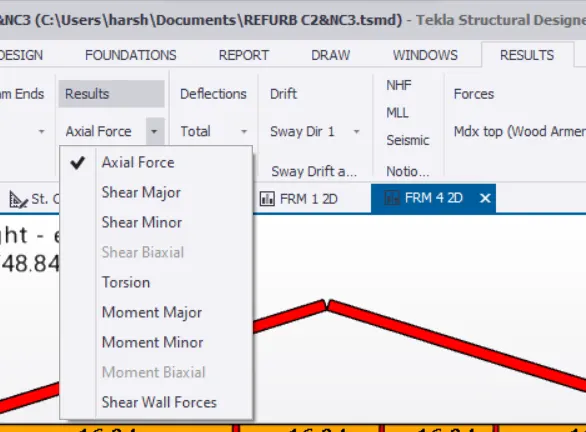
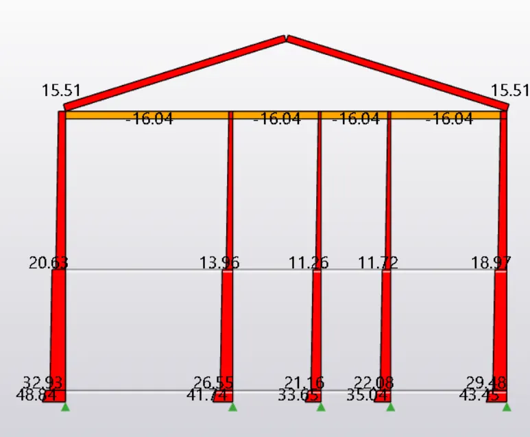
The below is the Axial Load Diagram of one Frame.
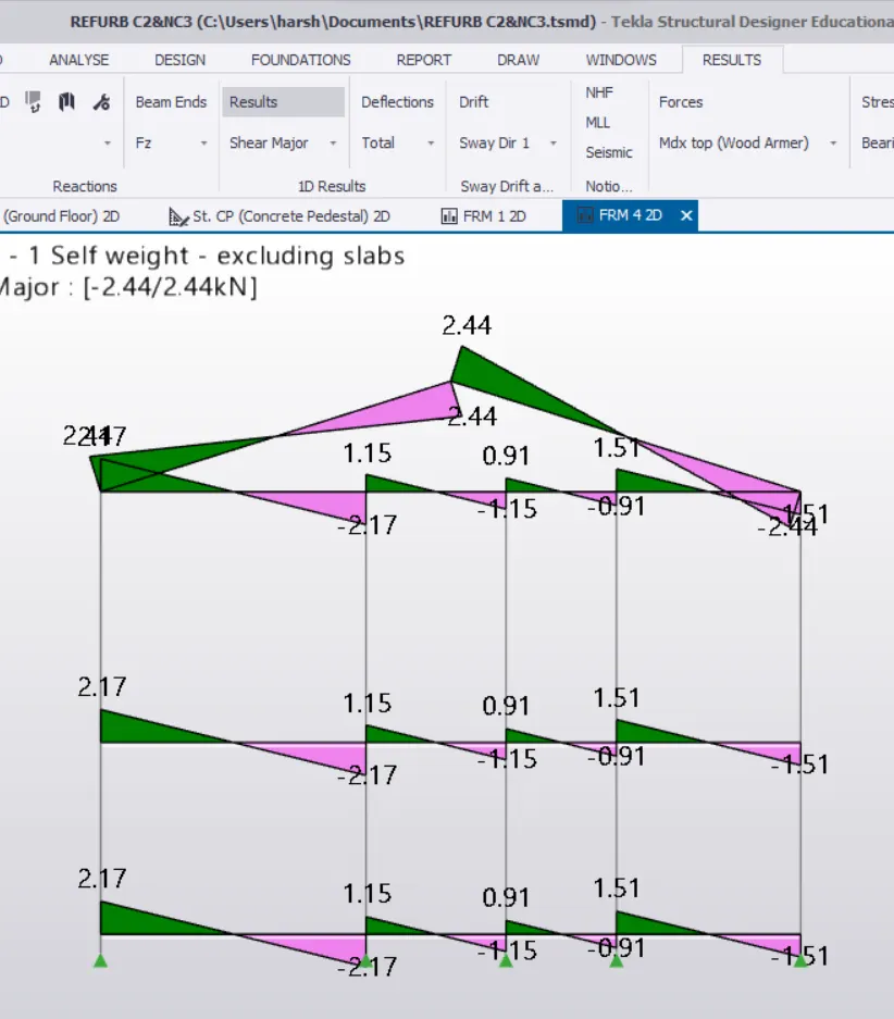
The below is the Shear Force Diagram of the same.
 9
9
And the below is the Bending Moment Diagram of the same.
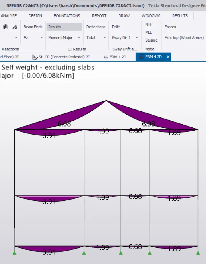
For all the above,we had selected only the Self Weight of the members.And in the similar manner,we can check for all the different loads and combinations.
Axial Load Diagram
From the above image of the Axial Load Diagram,we can find that most of the members are subjected to axial load and few for the tension.Where the axial load is the compression as the columns are subjected to the loads from above.
We can find the axial loading intensity increases from top to bottom,as the bottom members do carry the weight of the top members too.And the pedestals ultimately do carry everything,so they are subjected to high axial loading intensities.
And the rafters too,have to carry their own weight,so had been subjected to axial load due to it's self weight.
We can find the beam present at the top are subjected to tension,as these beams are used for connecting the columns from getting separated,so they experience the tension.
Shear Force Diagram
From the above image of Shear Force Diagram,we can find that all horizontal members as well as the slanting members are subjected to some shear load.And the columns are having the negilible shear force.As generally,the columns are subjected to only axial load but in some cases to moment as well and in rare cases the shear force.
And it's a common tendency that the beams or horizontal members do carry the shear force,and the same we can find from above.
As we consider the self weight,which is something which is distributed throughout the span,the shear force diagram is of linear degree.And due to the end reactions,the diagram starts and ends at the joints.
Bending Moment Diagram
From the above image of the Bending Moment Diagram,we cand find that all the horizontal and slanting members are experiencing a bending.Even we can find that some portions of the columns too are experiencing the moment a bit but of least value.And in this case,as we had selected only the selfweight,so the columns do not experience much but in other cases they too can experience a bit of moment.
As the rafters are of long lengths,they are experiencing a great moment as the moment is directly related to the distance of the members when subjected to loading.
In the similar manner,the beams span for lesser lengths at middle,so they have very less moment.
2)
After the analysis of the model,we go to the review mode,where we can find the members that have been passed or failed.Seeing those,we will get a clarity,what members have to be changed.
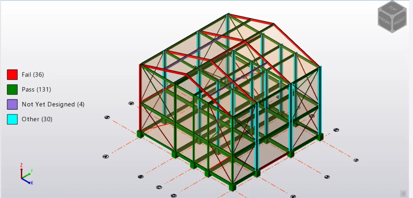
We can find a column placed at the grid lines intersection 5 & A.Reviewing it,we can find the reason for it's failure.
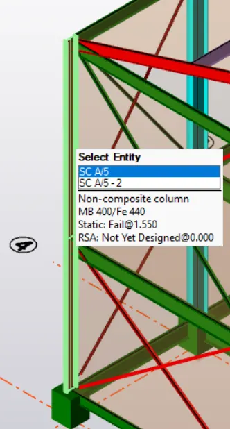
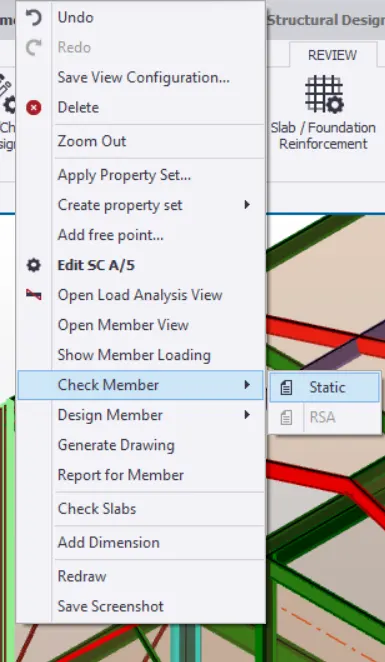
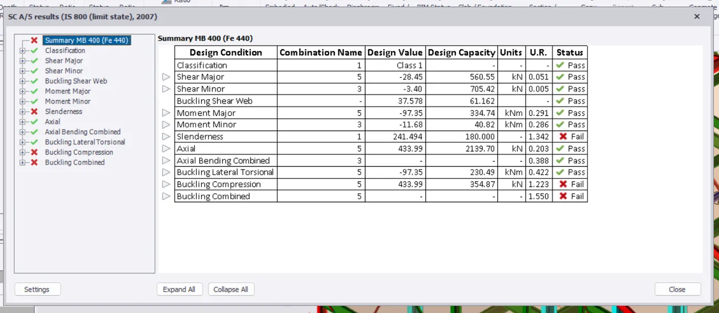
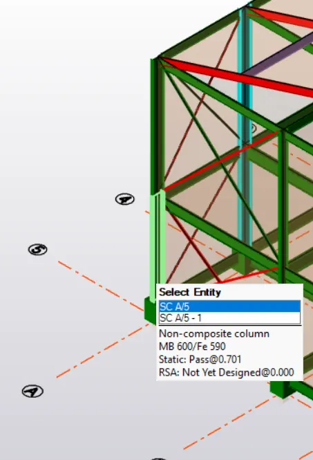
Where the member had been failed due to slenderness and buckling.Where the buckling and the slenderness can be prevented by increasing the size of the member.Where we change it from ISMB 400/Fe 440 to ISMB 600/Fe 590.
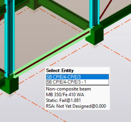
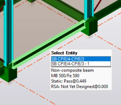
In the similar manner,we can find the bottom exterior tie beam had been failed where we had usen the ISMB 350/Fe 410 section,later it was changed to ISMB 500/Fe 590.
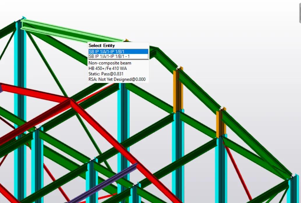
In the similar manner too,rafters have been failed due to slenderness,so they have been increased to higher section of ISHB 450+/Fe 410.
In this manner,we do change all the failed members.
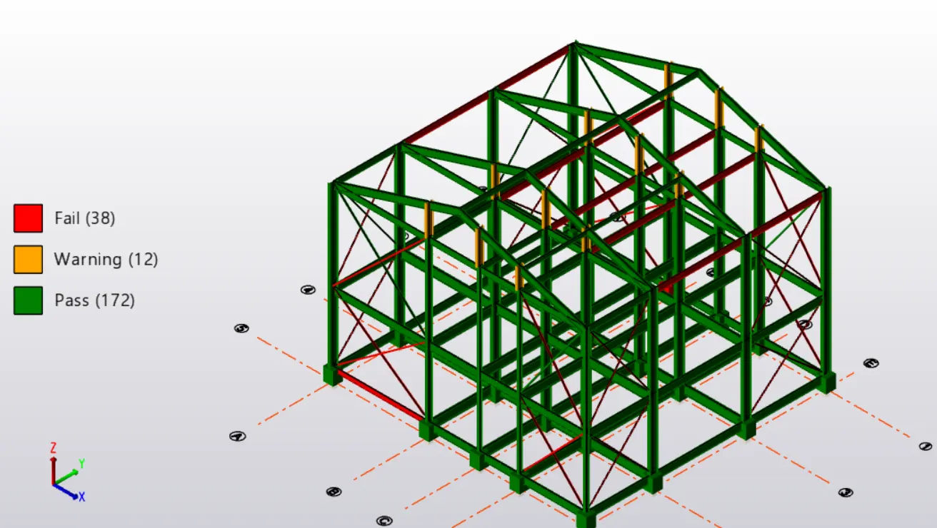
In the above manner,we have check all the members to pass all the members and to make the model economical when needed.We can find,after some process,the no. of passed members had been increased.So,with some more effort,we can reduce the no. of failed members and make all the members perfect.
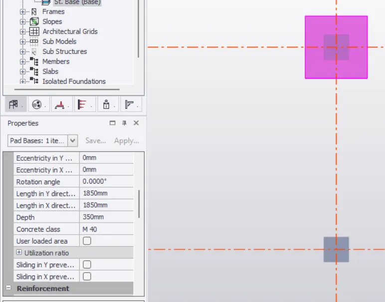
Now,we design the a footing.Initially,we go to FOUNDATION Tab>Pad Base Column,as we use the isolated footings.
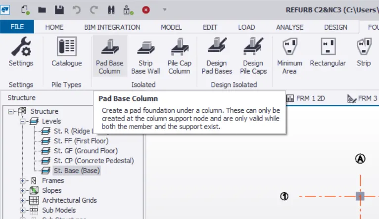
Where we then place a sample footing of the sample dimension with sample reinforcement.
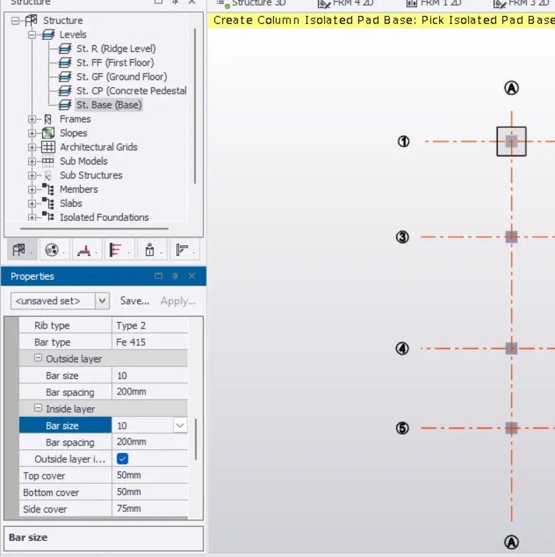
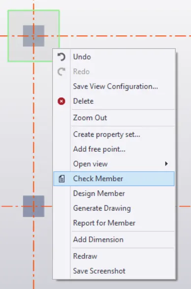
Where we use the option of Design Member,where then the software automatically calculates the required thickness of the footing along with the lateral dimensions too and the reinforcement also.