Suspension System Comparison using Simulink Blocks
AIM:
To plot a function using basic Simulink block and t run and study a simulink example “Suspension System Comparison”
SUSPENSION:
Suspension is the system of Tire (wheels), Tire air, spring, Shock absorber and linkage that connect a vehicle to its wheels and allow relative motion between two. Suspension system must support both road holding/handling and ride quality, which are at odd with each other. The tuning of suspension involves finding the right compromise. It is important for the suspension to keep the road wheel in contact with road surface as much as possible, because all the road or ground force acting on the vehicle do so through the contact patches of the tires. The suspension also protects the vehicle itself and any cargo or luggage from damage and wear. The design of front and rear suspension of a car may be different.
GOVERNING EQUATIONS:
`y(x)= (x-1) 〖.(x-3)〗^2.(x-9)^2`
OBJECTIVES:
- To plot above function using Simulink blocks.
- To study a Simulink Example and find answer for following question :-
- What is the objective of the Simulation? What are similarities and difference between the three systems under study?
- What is your observation from the results?
- How the Oscillating velocity source is created?
MODELS:
Function Model:
EXPLANATION:
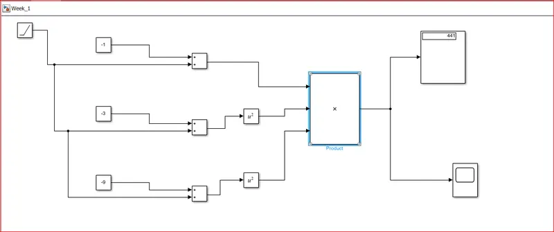
- In the above Simulink model, blocks that are used are sum block, constant block, ramp block, math function block, product block, display block and a scope block.
- 1st we have divided the function into 3 parts i.e. 1st part “(x-1)”, 2nd part”(x-3) ^2”, 3rd part “(x-9) ^2”. Then we can multiply all 3 parts to get the final answer of the function.
- Now to achieve 3 parts, we have taken the SUM BLOCK from the “Library Browser”, since we have 3 parts we take 3 SUM BLOCK. In the SUM BLOCK we can observe that the inputs are denoted by ‘+’ which means inputs will be added and the output will be their sum, we can also modify these inputs by double clicking in the sum block. This block can also be used for subtracting by changing the inputs of the SUM BLOCK.
- Here in the above model, without changing the inputs we have used this block. Now to one of the input of SUM BLOCK is connected by a CONSTANT BLOCK. This block helps use to give any constant value as inputs. Since in 1st part of equation constant value is “-1” so this value is given to CONSTANT BLOCK, This constant is 1 input for SUM BLOCK.
- Now in the 1st part of function, variable is ‘x’ so to represent this RAMP BLOCK is used .RAMP BLOCK is a signal which changes continuously with respect to time i.e. it acts like a variable. If we double click the RAMP BLOCK we can see a row where it is defined as “Slope”, this value is the increment value for the RAMP BLOCK i.e. the value in the RAMP BLOCK is increased by the value of slope for each second of time. By default the value of Slope is “1”, so in our Model RAMP BLOCK will increase by 1 for every second. Initial value and initial time for starting the RAMP BLOCK is set to”0” by default.
- Now this RAMP BLOCK is assigned as 2nd inputs for the SUM BLOCK. So by assigning the inputs to the sum block the output is given as (x-1), which is 1st part of our Function.
- Similarly for 2nd and 3rd part of the function same approach is used to find (x-3) and (x-9). Now to Square these term, the output of SUM BLOCK of these 2 terms is given input to a MATH FUNCTION BLOCK and by double clicking it we have selected Squaring Math Function in that block.
- Now Out of 1st SUM BLOCK, 1st MATH FUNCTION BLOCK and 2nd MATH FUNCTION BLOCK represent as (x-1),(x-3)^2,(x-9)^2 respectively. As per the Equation we have multiply all these term to get the final value of given Function.
- So these outputs are given as input to a 3x1 PRODUCT BLOCK. This block multiplies all the inputs and gives product of these inputs as output. Thus the output of this PRODUCT BLOCK will be”(x-1)*(x-3) ^2(x-9) ^2”.
- Now to display the output of this PRODUCT BLOCK, we have connected output of this block to DISPLAY BLOCK, which will display the results. For getting a graph, same output of PRODUCT BLOCK is connected to the SCOPE BLOCK, which will generate a graph representing the value of the function for each second of time.
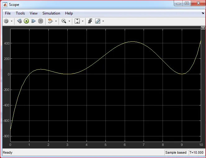
- Thus from the above figure we can observe that how the value of function is changing w.r.t. Time.
SUSPENSION SYSTEM COMPARISON:
OBJECTIVES OF SIMULATION:
- This simulation shows a testbed containing 3 sets of springs and damper excited by the same oscillating velocity source.
- To compare the 3 plots like (Shock Absorber, Non-linear spring, Variable spring) and analysis the Good Suspension System
SUSPENSION System:
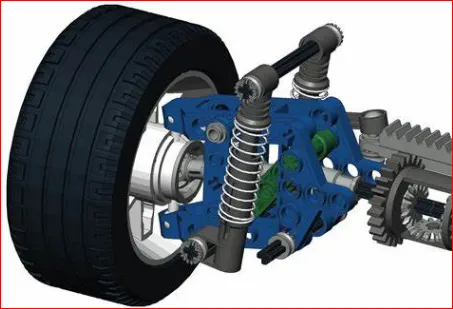
Suspension is the system of Tire (wheels), Tire air, spring, Shock absorber and linkage that connect a vehicle to its wheels and allow relative motion between two. Suspension system must support both road holding/handling and ride quality, which are at odd with each other. The tuning of suspension involves finding the right compromise. It is important for the suspension to keep the road wheel in contact with road surface as much as possible, because all the road or ground force acting on the vehicle do so through the contact patches of the tires. The suspension also protects the vehicle itself and any cargo or luggage from damage and wear. The design of front and rear suspension of a car may be different.
SHOCK ABSORBER:
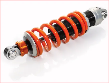
A Shock absorber or Damper is a mechanical or Hydraulic device designed to absorb and damp shock impulses. In a vehicle, shock absorber reduces the effect of traveling over rough ground, leading to improve ride quality and vehicle handling. While shock absorber serve the purpose of limiting excessive suspension movement, their intended sole purpose is to damp spring oscillation. Shock absorber use valving of oil and gasses to absorb excess energy from the springs. Spring rate are chosen by the manufacturer based on weight of vehicle (sprung weight), loaded and unloaded. Some people use shocks to modify spring rate but this is not correct use. Along with hysteresis in the tire itself, they damp the energy stored in the motion of the unsprung weight up and down. Effective wheel bounce damping may require tuning shock to an optimal resistance.
NON-LINEAR SPRING:
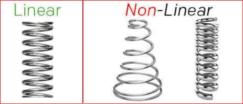
Nonlinear springs are helical coil spring that exerts an inconsistent amount of force as it is under a working load or torque. This means that the force needed to travel 1 inch, millimeter, or degree might not double when it travel 2 inch, millimeter, or degree like a linear spring would.
There are several types of non-linear spring in compression, extension and even torsional spring forms. These include conical/tapered springs, barrel springs (concave & convex) and dual-pitch springs.
VARIABLE SPRING:
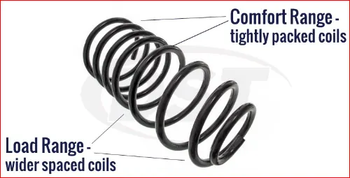
The variable spring rate increases with the spring deflection. The spring rate is not constant or linear. Variable pitch springs can have multiple rates or, while spring is compressing, they can have a progressively increasing or decreasing spring rate. By “varying” the pitch, or the center to center distance between the coils. By lessening the amount of active energy absorbing coils as they become inactive and no longer absorb energy during compression. Because some of the coils close up faster than the others, the spring, in turn, becomes stiffer and the rate increases.
Sprung weight transfer:
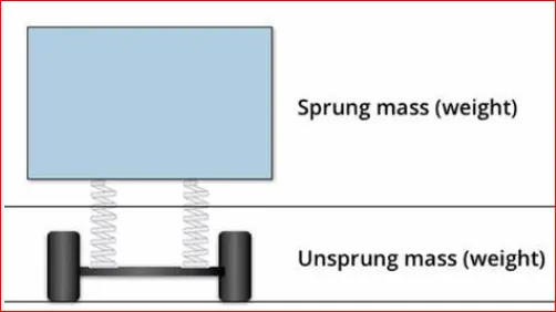
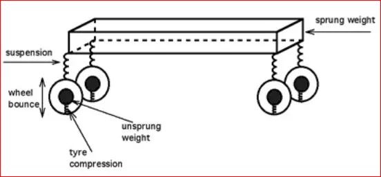
Sprung weight transfer is the weight transferred by only the weight of the vehicle resting on the springs, not the total vehicle weight. Calculating this requires knowing the vehicle’s sprung weight (total weight less than unsprung weight), the front and rear roll centre height and the sprung centre of gravity height (used to calculate the roll moment arm length). Calculating the front and rear sprung weight transfer will also require knowing the roll couple percentage.
Unsprung weight transfer:
Unsprung weight transfer is calculated based on the weight of the vehicle’s components that are not supported by the springs. This includes tires, wheels, brakes, spindles, half the control arm’s weight and the other component. These components are then (for calculation purpose) assumed to be connected to a vehicle with zero sprung weight. They are then put through same dynamic loads. The weight transfer from cornering in the front would be equal to the total unsprung front weight times the G-Force times the front unsprung centre of gravity height divided by the front track width. The same is true for rear.
OUTPUT RESULT:
EXAMPLE MODEL:
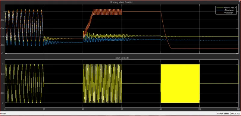
- This example shows a testbed containing 3 set of springs and dampers excited by the same oscillating velocity source.
- The 1st uses the Shock Absorber block and includes linear stiffness and damping. Optional friction and hard stops are not used.
- The 2nd Shock Absorber uses a Nonlinear Translational spring and a Nonlinear Translational Damper specified by symmetric polynomials.
- The 3rd uses a Variable Translational Spring and Variable Translation Damper. The spring constant is varied during the simulation using open loop control and the damping coefficient adjusts to ensure critical damping is achieved.
- From the above example
- The Objective the simulation is to observe how the 3 set of springs are excited by the same oscillating velocity source.
Here the velocity applied for all three is same.
Here the Tire Stiffness, Sprung mass and unsprung mass are same for all three.
Here the Stiffness and Damping for each suspension system is different .For Shock Absorber it changes linearly w.r.t Displacement, For Nonlinear Spring it changes non-linearly w.r.t Displacement and for Variable Spring it changes continuously.
- From the below results we can observe that, for low velocity the shock absorber and variable spring act similarly but the non-linear spring has slightly more negative sprung mass position. Now for medium velocity , the Shock Absorber and Nonlinear shows similar unequal positions of sprung mass i.e. the body is keeping on jumping up and down but in case of Variable Spring there is a sudden jump and then the position of sprung mass constant i.e. it is keeping the body stable. Now at Higher Velocities there is small change in Shock Absorber and Nonlinear Spring but the Variable Spring shows nearly constant value for the sprung mass position. So we can conclude at as the velocities increases the load is also increased so at higher loads variable spring is giving good output and at Medium and Small load Shock Absorber and Nonlinear spring are also giving good results but Variable Spring is giving better results at these velocities also. We can also see that when velocities are zero there are change in the Shock Absorber and Nonlinear Springs, but the Variable spring is constant for the Sprung Mass position.
VELOCITY SOURCE:
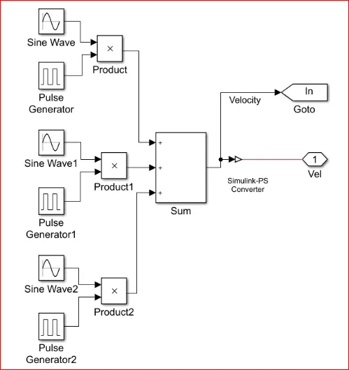
- Velocity Source is created by multiplying Sine Wave and Pulse Generator. By observing the below Diagram we can see 3 set of sine wave block and pulse generator block are multiplies individually and then all their product outputs are added together and converted into physical quantity. Now here set of Sine Wave and pulse generator represent each type of velocity i.e. first set represent slow velocity, second set represents Medium velocity and the third set represent High velocity. These different types of velocities are achieved by changing the Sine type parameter and Frequency parameter in Sine Wave block and by changing phase delay parameter in the Pulse in the Pulse generator. By changing this parameters we can achieve different velocities and all these velocity together are given as input to all 3 Suspension Systems.
CONCLUSION:
- Thus all the objectives are achieved successfully.
- Similar kind of approach can be used to plot and type of Function using Simulink.
- Various other Example can be studied and understood in the similar manner in