Study of Flow around a Circular Cylinder in Different Flow Regime and Von Kármán vortex street Flow Behaviour. ( Final Project / ITCFDML&OF )
AIM : Study of Flow around a Circular Cylinder in Different Flow Regime and Von Kármán vortex street Flow Behaviour.
OBJECTIVE :
- Performing simulation of Flow over a cylinder in OpenFoam
- Generating 2D Snappy Hex Mesh for the simulation
- Capturing vortex street Flow Behaviour at different Flow Regimes/ Reynolds No.
THEORY :
One of the classical problems in fluid mechanics is the determination of the flow field around a bluff body represented by a circular or rectangular cylinder. This is of great interest in many engineering applications, such as heat exchanger, chimney, hydrodynamic loading on ocean marine piles and offshore platform risers and support legs.
From scientific perspective, flow around a circular cylinder is having some important phenomenon of fluid dynamics, such as transition to turbulent, separation, and vortex shedding. From the following diagram we can see the flow characteristics over a circular cylinder surface. Boundary layer Formation, point of separation, and Wake Formation.
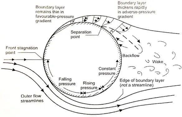
Laminar Boundary Layer ( Ref. [10] )
The different range of Reynolds Numbers represents different flow patterns. At low Reynolds Numbers, the flow pattern is observed to be Laminar i.e., Smooth, Constant fluid motion. At higher Reynolds Numbers the flow pattern is observed to be Turbulent i.e., Chaotic eddies, Vortices, and Flow instabilities. As shown in following example of nature,
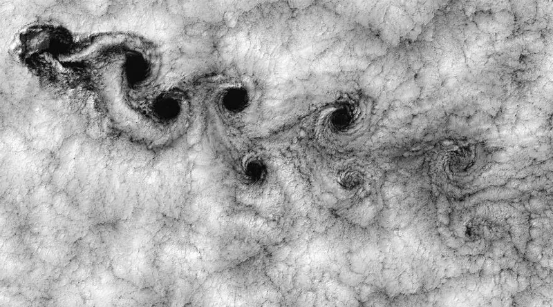
Turbulent Von Karman Vortex flow of Cloud ( Ref. [11] )
Due to the large low-pressure at wake region there is formation of the Vortices from backflow of the fluid. These vortices moves forward in the downstream and then these vortices get bigger due to diffusion. And this cause wake to grow and creat instabilities which can travel upstream and leads to vortex shedding.
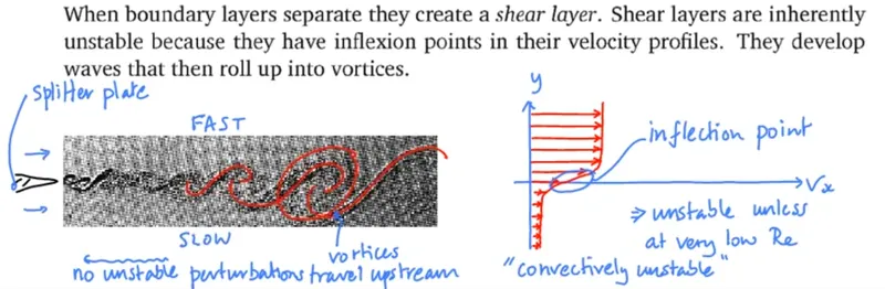
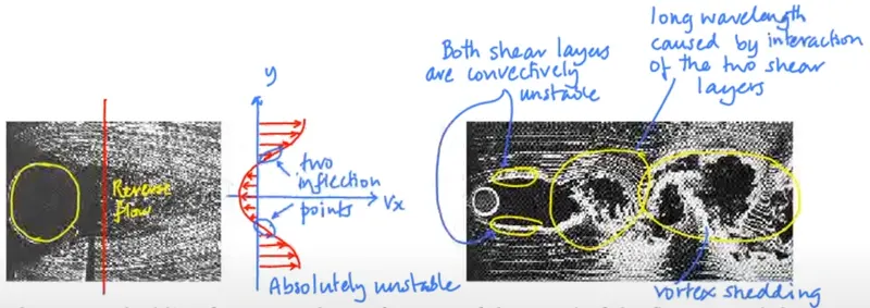
( Ref. [1] )
There are two approximately parallel shear layers behind a bluff body such as a cylinder. On the outside, the flow goes forwards. On the inside, it goes backwards. This situation is even more unstable than a single shear layer. The shear layers start by snaking up and down together. Soon they roll up into vortices that are shed alternately from each side of the cylinder. This is vortex shedding.
The vortex shedding frequency, f , is a function of the speed of the flow, V, and the distance between the shear layers, D. Experimentally one finds that the Strouhal number, f.D/V , is approximately 0.2 at moderate and high Reynolds numbers. Vortex shedding has important consequences for structures such as chimneys, particularly if the frequency of vortex shedding matches the resonant frequency of the structure.

( Ref. [1] )
In fluid dynamics, a Kármán vortex street (or a von Kármán vortex street) is a repeating pattern of swirling vortices, caused by the vortex shedding.
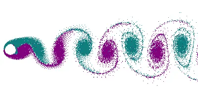
(Source: Wikipedia)
A vortex street will form only at a certain range of flow velocities, specified by a range of Reynolds numbers (Re). The (global) Reynolds number for a flow is a measure of the ratio of inertial to viscous forces in the flow of a fluid around a body or in a channel, and may be defined as a nondimensional parameter of the global speed of the whole fluid flow :
`R_e = (U*L)/nu` or `R_e = (rho*U*L)/mu`
where, `R_e =` Reynold's Number
`L =` Characteristic Length parameter of the body or channel
`U =` Free Stream Flow speed of the Fluid
`rho =` Density of the Fluid
`mu =` Kinematic Viscosity of the Fluid
`nu =` Dynamic Viscosity of the Fluid
From the Following Diagram, We can see the different Flow behaviour and Vortex Street at different Reynold's No. range across a circular cylinder :
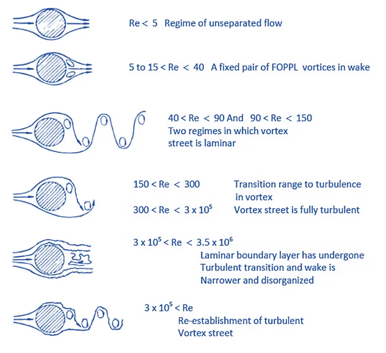
Flow Regime of Fluid Flow Across a Smooth Tube
Mathematical modeling of von Kármán vortex street can be performed using different techniques including solving the full Navier-Stokes equations with k-epsilon, SST, k-omega and Reynolds stress, and large eddy simulation (LES) turbulence models.
In this project we are simulating with RANS k-Omega SST Turbulence Model.
Following is a brief discription and usage about the RANS Turbulence Models:
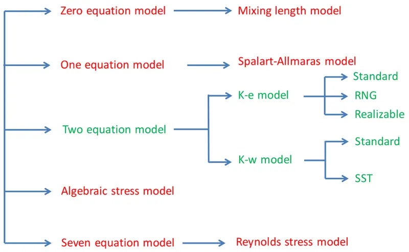
RANS Turbulence Model Descriptions
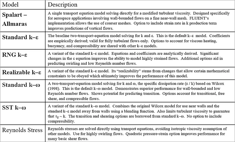
( Ref. [7] )
RANS Turbulence Model Behavior and Usage
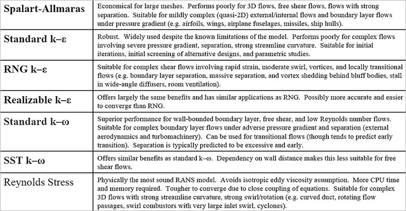
( Ref. [7] )
From all of the above turbulence models k-epsilon and k-Omega SST are the most common and used for most of the standard cases.
PARAMETERS & SETUP METHODLOGY :
Above we have seen different flow characteristics of flow over cylinder at different flow regimes,
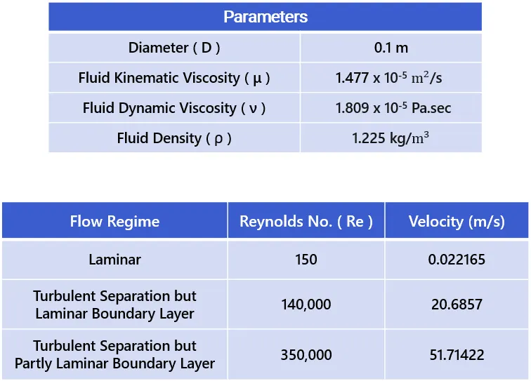
Therefore selecting three Reynold's no.s in this project i.e. -
a) Re = 150
b) Re = 150,000
a) Re = 350,000
Now, the Following are the Parameters considered for the Simulation -
SIMULATION SETUP :
1. Choosing Solver Based on the Type of the Problem -
In this project we are taking the reference of the Open Foam tutorial Wing Motion, located at
../tutorials/incompressible/pimpleFoam/RAS/wingMotion/wingMotion2D_simpleFoam
2. Geometry and Meshing
The given Geometry and Dimensions of the geometry, is shown below -
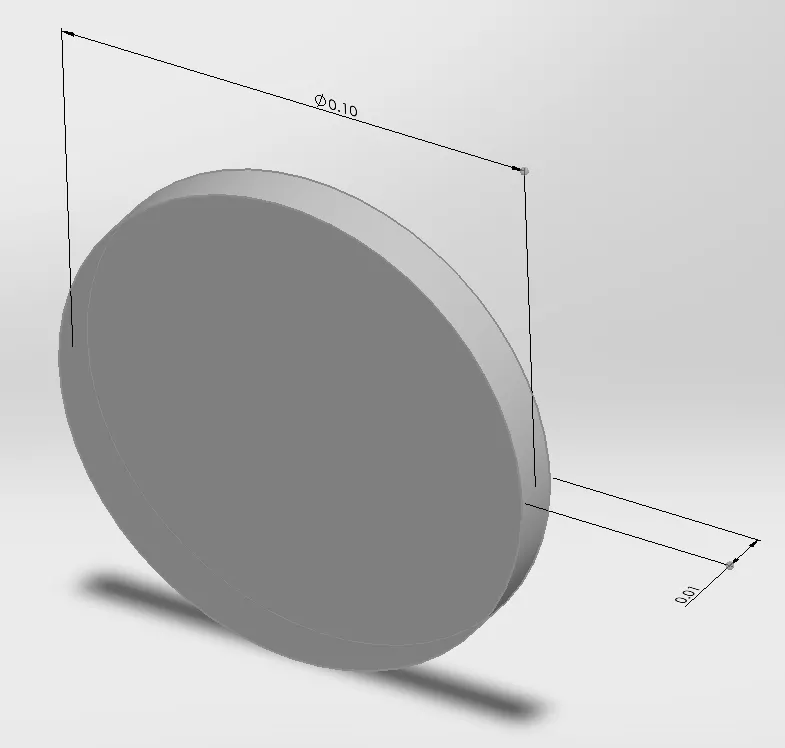
D = 0.1 m, R = 0.05 m, L =0.01 m,
Computational domain as shown below -
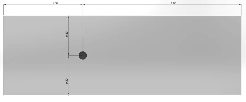
( Units in ' Meters (m) ' )
Meshing -
In this simulation we're using 2D-Snappy Hex Mesh, the 2D-snappy hex mesh requires 4 Dict Files, i.e.
1. blockMeshDict - defines the computational domain, inlet, outlet and other boundries.
2. surfaceFeaturesDict - it extracts the CAD files like STL, OBJ, etc. and embeds them in the openfoam, at constant folder at polymesh and triSurface folder as ".eMesh"
3. snappyHexMeshDict - defines the direction and instructions for creating a snappy hex mesh over the extracted CAD surface and domain.
4. extrudeMeshDict - it converts the 3D Snappy Hex Mesh generated initially into a 2D Mesh.
NOTE : We are using Same Mesh for all three flow conditions .
blockMeshDict File -
/*--------------------------------*- C++ -*----------------------------------*
  =========                 |
        /  F ield         | OpenFOAM: The Open Source CFD Toolbox
       /   O peration     | Website:  https://openfoam.org
      /    A nd           | Version:  9
     /     M anipulation  |
*---------------------------------------------------------------------------*/
FoamFile
{
    format      ascii;
    class       dictionary;
    object      blockMeshDict;
}
// * * * * * * * * * * * * * * * * * * * * * * * * * * * * * * * * * * * * * //

convertToMeters 1;

vertices
(
    /* 0 */  (-1 -0.5 -0.005)
    /* 1 */  (2 -0.5 -0.005)
    /* 2 */  (2 0.5 -0.005)
    /* 3 */  (-1 0.5 -0.005)
    /* 4 */  (-1 -0.5 0.005)
    /* 5 */  (2 -0.5 0.005)
    /* 6 */  (2 0.5 0.005)
    /* 7 */  (-1 0.5 0.005)

);

blocks
(
    hex (0 1 2 3 4 5 6 7)  (180 120 1)  simpleGrading (1 1 1)
);

edges
(
);

boundary
(
    inlet
    {
        type patch;
        faces
        (
            (0 4 7 3)
        );
    }

    outlet
    {
        type patch;
        faces
        (
            (2 6 5 1)
        );
    }

    topAndBottom
    {
        type symmetry;
        faces
        (
            (3 7 6 2)
            (1 5 4 0)
        );
    }

    front
    {
        type patch;
        faces
        (
            (4 5 6 7)
        );
    }

    back
    {
        type patch;
        faces
        (
            (0 3 2 1)
        );
    }
);


// ************************************************************************* //
surfaceFeaturesDict File -
/*--------------------------------*- C++ -*----------------------------------*
  =========                 |
        /  F ield         | OpenFOAM: The Open Source CFD Toolbox
       /   O peration     | Website:  https://openfoam.org
      /    A nd           | Version:  9
     /     M anipulation  |
*---------------------------------------------------------------------------*/
FoamFile
{
    format      ascii;
    class       dictionary;
    object      surfaceFeaturesDict;
}
// * * * * * * * * * * * * * * * * * * * * * * * * * * * * * * * * * * * * * //

surfaces
(
    "cylinder.stl"
);

// Identify edges when angle between faces < includedAngle
includedAngle       150;

//curvature true;

// Include region boundaries as features
//geometricTestOnly   yes;

subsetFeatures
{
    // Include only edges that intersect the plane
    // plane
    // {
    //     planeType       pointAndNormal;
    //     point           (0 0 0);
    //     normal          (1 0 0);
    // }

    // Include only edges inside the box
    // insideBox           (0 0 0)(1 1 1);

    // Include only edges outside the box
    // outsideBox          (0 0 0)(1 1 1);

    // Include nonManifold edges (edges with >2 connected faces)
    nonManifoldEdges    yes;

    // Include open edges (edges with 1 connected face)
    openEdges           yes;
}

trimFeatures
{
    // Remove features with fewer than the specified number of edges
    minElem         0;

    // Remove features shorter than the specified cumulative length
    minLen          0.0;
}

// Write features to obj format for visualisation
writeObj            yes;
verboseObj          no;


// ************************************************************************* //
snappyHexMeshDict File -
/*--------------------------------*- C++ -*----------------------------------*
  =========                 |
        /  F ield         | OpenFOAM: The Open Source CFD Toolbox
       /   O peration     | Website:  https://openfoam.org
      /    A nd           | Version:  9
     /     M anipulation  |
*---------------------------------------------------------------------------*/
FoamFile
{
    version     2.0;
    format      ascii;
    class       dictionary;
    object      snappyHexMeshDict;
}
// * * * * * * * * * * * * * * * * * * * * * * * * * * * * * * * * * * * * * //

// Which of the steps to run
castellatedMesh true;
snap            true;
addLayers       true;


// Geometry. Definition of all surfaces. All surfaces are of class
// searchableSurface.
// Surfaces are used
// - to specify refinement for any mesh cell intersecting it
// - to specify refinement for any mesh cell inside/outside/near
// - to 'snap' the mesh boundary to the surface
geometry
{
    cylinder.stl
    {
        type triSurfaceMesh;
        name cylinder;
    }

    refinementBox
    {
        type searchableBox;
        min (-0.5 -0.1 -1);
        max ( 5  0.1  1);
    }
};


// Settings for the castellatedMesh generation.
castellatedMeshControls
{

    // Refinement parameters
    // ~~~~~~~~~~~~~~~~~~~~~

    // If local number of cells is >= maxLocalCells on any processor
    // switches from from refinement followed by balancing
    // (current method) to (weighted) balancing before refinement.
    maxLocalCells 25000000;

    // Overall cell limit (approximately). Refinement will stop immediately
    // upon reaching this number so a refinement level might not complete.
    // Note that this is the number of cells before removing the part which
    // is not 'visible' from the keepPoint. The final number of cells might
    // actually be a lot less.
    maxGlobalCells 100000000;

    // The surface refinement loop might spend lots of iterations refining just
    // a few cells. This setting will cause refinement to stop if <=
    // minimumRefine are selected for refinement. Note: it will at least do one
    // iteration (unless the number of cells to refine is 0)
    minRefinementCells 0;

    // Number of buffer layers between different levels.
    // 1 means normal 2:1 refinement restriction, larger means slower
    // refinement.
    nCellsBetweenLevels 8;


    // Explicit feature edge refinement
    // ~~~~~~~~~~~~~~~~~~~~~~~~~~~~~~~~

    // Specifies a level for any cell intersected by its edges.
    // This is a featureEdgeMesh, read from constant/triSurface for now.
    features
    (
      {
        file "cylinder.eMesh";
        level 6;
      }
    );


    // Surface based refinement
    // ~~~~~~~~~~~~~~~~~~~~~~~~

    // Specifies two levels for every surface. The first is the minimum level,
    // every cell intersecting a surface gets refined up to the minimum level.
    // The second level is the maximum level. Cells that 'see' multiple
    // intersections where the intersections make an
    // angle > resolveFeatureAngle get refined up to the maximum level.

    refinementSurfaces
    {
        cylinder
        {
            // Surface-wise min and max refinement level
            level (6 6);
        }
    }

    // Resolve sharp angles on fridges
    resolveFeatureAngle 5;


    // Region-wise refinement
    // ~~~~~~~~~~~~~~~~~~~~~~

    // Specifies refinement level for cells in relation to a surface. One of
    // three modes
    // - distance. 'levels' specifies per distance to the surface the
    //   wanted refinement level. The distances need to be specified in
    //   descending order.
    // - inside. 'levels' is only one entry and only the level is used. All
    //   cells inside the surface get refined up to the level. The surface
    //   needs to be closed for this to be possible.
    // - outside. Same but cells outside.

    refinementRegions
    {
        refinementBox
        {
            mode inside;
            levels ((1e15 2));
        }
    }


    // Mesh selection
    // ~~~~~~~~~~~~~~

    // After refinement patches get added for all refinementSurfaces and
    // all cells intersecting the surfaces get put into these patches. The
    // section reachable from the locationInMesh is kept.
    // NOTE: This point should never be on a face, always inside a cell, even
    // after refinement.
    locationInMesh (-0.5 -0.1 0);


    // Whether any faceZones (as specified in the refinementSurfaces)
    // are only on the boundary of corresponding cellZones or also allow
    // free-standing zone faces. Not used if there are no faceZones.
    allowFreeStandingZoneFaces true;
}


// Settings for the snapping.
snapControls
{
    //- Number of patch smoothing iterations before finding correspondence
    //  to surface
    nSmoothPatch 3;

    //- Relative distance for points to be attracted by surface feature point
    //  or edge. True distance is this factor times local
    //  maximum edge length.
    tolerance 2.0;

    //- Number of mesh displacement relaxation iterations.
    nSolveIter 100;

    //- Maximum number of snapping relaxation iterations. Should stop
    //  before upon reaching a correct mesh.
    nRelaxIter 5;

    //- Highly experimental and wip: number of feature edge snapping
    //  iterations. Leave out altogether to disable.
    nFeatureSnapIter 5;
}


// Settings for the layer addition.
addLayersControls
{
    // Are the thickness parameters below relative to the undistorted
    // size of the refined cell outside layer (true) or absolute sizes (false).
    relativeSizes false;

    // Per final patch (so not geometry!) the layer information
    layers
    {
        "cylinder.*"
        {
            nSurfaceLayers 10;
        }
    }

    // Expansion factor for layer mesh
    expansionRatio 1.2;

    //- Wanted thickness of final added cell layer. If multiple layers
    //  is the
    //  thickness of the layer furthest away from the wall.
    //  Relative to undistorted size of cell outside layer.
    //  is the thickness of the layer furthest away from the wall.
    //  See relativeSizes parameter.
    finalLayerThickness 0.001;

    //- Minimum thickness of cell layer. If for any reason layer
    //  cannot be above minThickness do not add layer.
    //  Relative to undistorted size of cell outside layer.
    //  See relativeSizes parameter.
    minThickness 0.00001;

    //- If points get not extruded do nGrow layers of connected faces that are
    //  also not grown. This helps convergence of the layer addition process
    //  close to features.
    // Note: changed(corrected) w.r.t 17x! (didn't do anything in 17x)
    nGrow 0;

    // Advanced settings

    //- When not to extrude surface. 0 is flat surface, 90 is when two faces
    //  make straight angle.
    featureAngle 90;

    //- Maximum number of snapping relaxation iterations. Should stop
    //  before upon reaching a correct mesh.
    nRelaxIter 5;

    // Number of smoothing iterations of surface normals
    nSmoothSurfaceNormals 1;

    // Number of smoothing iterations of interior mesh movement direction
    nSmoothNormals 3;

    // Smooth layer thickness over surface patches
    nSmoothThickness 10;

    // Stop layer growth on highly warped cells
    maxFaceThicknessRatio 0.5;

    // Reduce layer growth where ratio thickness to medial
    // distance is large
    maxThicknessToMedialRatio 0.3;

    // Angle used to pick up medial axis points
    // Note: changed(corrected) w.r.t 16x! 90 degrees corresponds to 130 in 16x.
    minMedianAxisAngle 90;

    // Create buffer region for new layer terminations
    nBufferCellsNoExtrude 1;


    // Overall max number of layer addition iterations. The mesher will exit
    // if it reaches this number of iterations; possibly with an illegal
    // mesh.
    nLayerIter 50;
}


// Generic mesh quality settings. At any undoable phase these determine
// where to undo.

  meshQualityControls
{
    //- Maximum non-orthogonality allowed. Set to 180 to disable.
    maxNonOrtho 80;

    //- Max skewness allowed. Set to <0 to disable.
    maxBoundarySkewness 20;
    maxInternalSkewness 4;

    //- Max concaveness allowed. Is angle (in degrees) below which concavity
    //  is allowed. 0 is straight face, <0 would be convex face.
    //  Set to 180 to disable.
    maxConcave 80;

    //- Minimum pyramid volume. Is absolute volume of cell pyramid.
    //  Set to a sensible fraction of the smallest cell volume expected.
    //  Set to very negative number (e.g. -1E30) to disable.
    minVol 1e-13;

    //- Minimum quality of the tet formed by the face-centre
    //  and variable base point minimum decomposition triangles and
    //  the cell centre. This has to be a positive number for tracking
    //  to work. Set to very negative number (e.g. -1E30) to
    //  disable.
    //     <0 = inside out tet,
    //      0 = flat tet
    //      1 = regular tet
    minTetQuality 1e-30;

    //- Minimum face area. Set to <0 to disable.
    minArea 1e-30;

    //- Minimum face twist. Set to <-1 to disable. dot product of face normal
    //- and face centre triangles normal
    minTwist 0.02;

    //- minimum normalised cell determinant
    //- 1 = hex, <= 0 = folded or flattened illegal cell
    minDeterminant 0.001;

    //- minFaceWeight (0 -> 0.5)
    minFaceWeight 0.02;

    //- minVolRatio (0 -> 1)
    minVolRatio 0.01;

    //must be >0 for Fluent compatibility
    minTriangleTwist 0.01;


    // Advanced

    //- Number of error distribution iterations
    nSmoothScale 4;
    //- amount to scale back displacement at error points
    errorReduction 0.8;

}


// Advanced

// Flags for optional output
// 0 : only write final meshes
// 1 : write intermediate meshes
// 2 : write volScalarField with cellLevel for postprocessing
// 4 : write current intersections as .obj files
debug 0;


// Merge tolerance. Is fraction of overall bounding box of initial mesh.
// Note: the write tolerance needs to be higher than this.
mergeTolerance 1e-6;


// ************************************************************************* //

// Merge tolerance. Is fraction of overall bounding box of initial mesh.
// Note: the write tolerance needs to be higher than this.
mergeTolerance 1e-6;

// ************************************************************************* //
extrudeMeshDict File -
/*--------------------------------*- C++ -*----------------------------------*
  =========                 |
        /  F ield         | OpenFOAM: The Open Source CFD Toolbox
       /   O peration     | Website:  https://openfoam.org
      /    A nd           | Version:  9
     /     M anipulation  |
*---------------------------------------------------------------------------*/
FoamFile
{
    format      ascii;
    class       dictionary;
    object      extrudeMeshDict;
}
// * * * * * * * * * * * * * * * * * * * * * * * * * * * * * * * * * * * * * //

// What to extrude:
//      patch   : from patch of another case ('sourceCase')
//      mesh    : as above but with original case included
//      surface : from externally read surface

constructFrom patch;
sourceCase "/home/raven/OpenFOAM/raven-9/run/Cylinder";
sourcePatches (front);

// If construct from patch: patch to use for back (can be same as sourcePatch)
exposedPatchName back;

// Flip surface normals before usage. Valid only for extrude from surface or
// patch.
flipNormals false;

//- Linear extrusion in point-normal direction
extrudeModel        linearNormal;

nLayers             1;

expansionRatio      1.0;

linearNormalCoeffs
{
    thickness       0.01;
}

// Do front and back need to be merged? Usually only makes sense for 360
// degree wedges.
mergeFaces false;   // true;

// Merge small edges. Fraction of bounding box.
mergeTol 0;


// * * * * * * * * * * * * * * * * * * * * * * * * * * * * * * * * * * * * * //
Simulation Setup -
All simulation Files/Dicts are same for all the case just the U file has change in the velocity value and Turbulence model is same RAS k-omega SST for the Re= 140,000 and 350,000 , for Re=150 the condition is laminar.
controlDict File -
/*--------------------------------*- C++ -*----------------------------------*
  =========                 |
        /  F ield         | OpenFOAM: The Open Source CFD Toolbox
       /   O peration     | Website:  https://openfoam.org
      /    A nd           | Version:  9
     /     M anipulation  |
*---------------------------------------------------------------------------*/
FoamFile
{
    format      ascii;
    class       dictionary;
    location    "system";
    object      controlDict;
}
// * * * * * * * * * * * * * * * * * * * * * * * * * * * * * * * * * * * * * //

application     simpleFoam;

startFrom       latestTime;

startTime       0;

stopAt          endTime;

endTime         10;

deltaT          0.01;

writeControl    runTime;

writeInterval   0.02;

purgeWrite      0;

writeFormat     binary;

writePrecision  6;

writeCompression off;

timeFormat      general;

timePrecision   6;

runTimeModifiable true;

functions
{
    forces
    {
        type                forces;
        libs                ("libforces.so");
        writeControl        timeStep;
        writeInterval       1;
        patches             (cylinder);
        rho                 rhoInf;
        log                 true;
        rhoInf              1.225;
        CofR                (0 0 0);
    }
}


// ************************************************************************* //
Initial and Boundary Conditions -
P -
/*--------------------------------*- C++ -*----------------------------------*
  =========                 |
        /  F ield         | OpenFOAM: The Open Source CFD Toolbox
       /   O peration     | Website:  https://openfoam.org
      /    A nd           | Version:  9
     /     M anipulation  |
*---------------------------------------------------------------------------*/
FoamFile
{
    format      ascii;
    class       volScalarField;
    object      p;
}
// * * * * * * * * * * * * * * * * * * * * * * * * * * * * * * * * * * * * * //

dimensions      [0 2 -2 0 0 0 0];

internalField   uniform 0;

boundaryField
{
    inlet
    {
        type            zeroGradient;
    }

    outlet
    {
        type            fixedValue;
        value           uniform 0;
    }

    cylinder
    {
        type            zeroGradient;
    }

    front
    {
        type            zeroGradient;
    }

    back
    {
        type            zeroGradient;
    }

    topAndBottom
    {
        type            symmetry;
    }
}

// ************************************************************************* //
U -
U File for Re=140,000. For Re=150 and Re=350,000 U file be same just the value willl be 0.022165m/s & 51.71422m/s respectively in the place of 20.6857 m/s.
/*--------------------------------*- C++ -*----------------------------------*
  =========                 |
        /  F ield         | OpenFOAM: The Open Source CFD Toolbox
       /   O peration     | Website:  https://openfoam.org
      /    A nd           | Version:  9
     /     M anipulation  |
*---------------------------------------------------------------------------*/
FoamFile
{
    format      ascii;
    class       volVectorField;
    location    "0";
    object      U;
}
// * * * * * * * * * * * * * * * * * * * * * * * * * * * * * * * * * * * * * //

dimensions      [0 1 -1 0 0 0 0];

internalField   uniform (20.6857 0 0);

boundaryField
{
    inlet
    {
        type            fixedValue;
        value           $internalField;
    }

    outlet
    {
        type            inletOutlet;
        inletValue      uniform (20.6857 0 0);
        value           $internalField;
    }

    cylinder
    {
        type            noSlip;
    }

    front
    {
        type            slip;
    }

    back
    {
        type            slip;
    }

    topAndBottom
    {
        type            symmetry;
    }
}

// ************************************************************************* //
nut -
/*--------------------------------*- C++ -*----------------------------------*
  =========                 |
        /  F ield         | OpenFOAM: The Open Source CFD Toolbox
       /   O peration     | Website:  https://openfoam.org
      /    A nd           | Version:  9
     /     M anipulation  |
*---------------------------------------------------------------------------*/
FoamFile
{
    format      ascii;
    class       volScalarField;
    location    "0";
    object      nut;
}
// * * * * * * * * * * * * * * * * * * * * * * * * * * * * * * * * * * * * * //

dimensions      [0 2 -1 0 0 0 0];

internalField   uniform 0;

boundaryField
{

   inlet
    {
        type            fixedValue;
        value           $internalField;
    }

    outlet
    {
        type            inletOutlet;
        inletValue      $internalField;
        value           $internalField;
    }

    cylinder
    {
        type            nutkWallFunction;
        value           uniform 0;
    }

    front
    {
        type            zeroGradient;
    }

    back
    {
        type            zeroGradient;
    }

    topAndBottom
    {
        type            symmetry;
    }
}


// ************************************************************************* //
k -
this file will in 0 folder only for the cases of Re= 140,000 & 350,000
/*--------------------------------*- C++ -*----------------------------------*
  =========                 |
        /  F ield         | OpenFOAM: The Open Source CFD Toolbox
       /   O peration     | Website:  https://openfoam.org
      /    A nd           | Version:  9
     /     M anipulation  |
*---------------------------------------------------------------------------*/
FoamFile
{
    format      ascii;
    class       volScalarField;
    object      k;
}
// * * * * * * * * * * * * * * * * * * * * * * * * * * * * * * * * * * * * * //

dimensions      [0 2 -2 0 0 0 0];

internalField   uniform 0.0096;

boundaryField
{
    inlet
    {
        type            fixedValue;
        value           $internalField;
    }

    outlet
    {
        type            inletOutlet;
        inletValue      $internalField;
        value           $internalField;
    }

    cylinder
    {
        type            kqRWallFunction;
        value       	$internalField;
    }

    front
    {
        type            zeroGradient;
    }

    back
    {
        type            zeroGradient;
    }

    topAndBottom
    {
        type            symmetry;
    }
}


// ************************************************************************* //
omega -
this file will in 0 folder only for the cases of Re= 140,000 & 350,000
/*--------------------------------*- C++ -*----------------------------------*
  =========                 |
        /  F ield         | OpenFOAM: The Open Source CFD Toolbox
       /   O peration     | Website:  https://openfoam.org
      /    A nd           | Version:  9
     /     M anipulation  |
*---------------------------------------------------------------------------*/
FoamFile
{
    format      ascii;
    class       volScalarField;
    object      omega;
}
// * * * * * * * * * * * * * * * * * * * * * * * * * * * * * * * * * * * * * //

dimensions      [0 0 -1 0 0 0 0];

internalField   uniform 32;

boundaryField
{
    inlet
    {
        type            fixedValue;
        value           $internalField;
    }

    outlet
    {
        type            inletOutlet;
        inletValue      $internalField;
        value           $internalField;
    }

    cylinder
    {
        type            omegaWallFunction;
        value           $internalField;
    }

    front
    {
        type            zeroGradient;
    }

    back
    {
        type            zeroGradient;
    }

    topAndBottom
    {
        type            symmetry;
    }
}


// ************************************************************************* //
transportProperties File -
this file remain in the constant folder which defines the fluid properties, and same for all the 3 flow condition.
/*--------------------------------*- C++ -*----------------------------------*
  =========                 |
        /  F ield         | OpenFOAM: The Open Source CFD Toolbox
       /   O peration     | Website:  https://openfoam.org
      /    A nd           | Version:  9
     /     M anipulation  |
*---------------------------------------------------------------------------*/
FoamFile
{
    format      ascii;
    class       dictionary;
    object      transportProperties;
}

// * * * * * * * * * * * * * * * * * * * * * * * * * * * * * * * * * * * * * //

transportModel Newtonian;

nu              [0 2 -1 0 0 0 0] 1.470e-05;

// ************************************************************************* //
turbulenceProperties File -
For Re= 140,000 and 350,000,
/*--------------------------------*- C++ -*----------------------------------*
  =========                 |
        /  F ield         | OpenFOAM: The Open Source CFD Toolbox
       /   O peration     | Website:  https://openfoam.org
      /    A nd           | Version:  9
     /     M anipulation  |
*---------------------------------------------------------------------------*/
FoamFile
{
    version     2.0;
    format      ascii;
    class       dictionary;
    location    "constant";
    object      turbulenceProperties;
}
// * * * * * * * * * * * * * * * * * * * * * * * * * * * * * * * * * * * * * //

simulationType RAS;

RAS
{
    RASModel        kOmegaSST;

    turbulence      on;

    printCoeffs     on;
}

// ************************************************************************* //
For Re=150,
/*--------------------------------*- C++ -*----------------------------------*
  =========                 |
        /  F ield         | OpenFOAM: The Open Source CFD Toolbox
       /   O peration     | Website:  https://openfoam.org
      /    A nd           | Version:  9
     /     M anipulation  |
*---------------------------------------------------------------------------*/
FoamFile
{
    version     2.0;
    format      ascii;
    class       dictionary;
    location    "constant";
    object      turbulenceProperties;
}
// * * * * * * * * * * * * * * * * * * * * * * * * * * * * * * * * * * * * * //

simulationType laminar;
FVSchemes & FVSolution :
fvschemes and fvSolution files are there in the system folder.
fvSchemes script file sets the numerical schemes for terms, such as derivatives in equations, that are calculated during a simulation.
The equation solvers, tolerances and algorithms are controlled from the fvSolution dictionary in the system directory. Below in our problem, set of entries from the fvSolution dictionary required for the icoFoam solver.
fvSchemes -
/*--------------------------------*- C++ -*----------------------------------*
  =========                 |
        /  F ield         | OpenFOAM: The Open Source CFD Toolbox
       /   O peration     | Website:  https://openfoam.org
      /    A nd           | Version:  9
     /     M anipulation  |
*---------------------------------------------------------------------------*/
FoamFile
{
    version         2;
    format          ascii;
    class           dictionary;
    object          fvSchemes;
}

ddtSchemes
{
    default         steadyState;
}

gradSchemes
{
    default         Gauss linear;
    grad(p)         Gauss linear;
    unlimitedGrad(U) Gauss linear;
}

divSchemes
{
    default         none;
    div(phi,U)      bounded Gauss linearUpwindV unlimitedGrad(U);
    turbulence      bounded Gauss limitedLinear 1;
    div(phi,k)      bounded Gauss limitedLinear 1;
    div(phi,omega)  bounded Gauss limitedLinear 1;
    div(phi,nuTilda) bounded Gauss limitedLinear 1;
    div(phi,epsilon) bounded Gauss limitedLinear 1;
    div(phi,phit)   bounded Gauss limitedLinear 1;
    div(phi,f)      bounded Gauss limitedLinear 1;
    div(phi,gammaInt) bounded Gauss linearUpwind grad;
    div(phi,ReThetat) bounded Gauss linearUpwind grad;
    div((nuEff*dev2(T(grad(U))))) Gauss linear;
}

laplacianSchemes
{
    default         Gauss linear limited corrected 0.33;
}

interpolationSchemes
{
    default         linear;
}

snGradSchemes
{
    default         limited corrected 0.33;
}

wallDist
{
    method          meshWave;
}

geometry
{
    type            highAspectRatio;
    minAspect       10;
    maxAspect       100;
}


// ************************************************************************* //
fvSolution -
/*--------------------------------*- C++ -*----------------------------------*
  =========                 |
        /  F ield         | OpenFOAM: The Open Source CFD Toolbox
       /   O peration     | Website:  https://openfoam.org
      /    A nd           | Version:  9
     /     M anipulation  |
*---------------------------------------------------------------------------*/
FoamFile
{
    version     2.0;
    format      ascii;
    class       dictionary;
    object      fvSolution;
}
// * * * * * * * * * * * * * * * * * * * * * * * * * * * * * * * * * * * * * //

solvers
{
    p
    {
        solver          GAMG;
        smoother        GaussSeidel;
        tolerance       1e-06;
        relTol          0.1;
    }

    "(U|k|omega|nuTilda|gammaInt|ReThetat)"
    {
        solver          smoothSolver;
        smoother        symGaussSeidel;
        tolerance       1e-08;
        relTol          0.1;
        maxIter         50;
    }

    "(epsilon|phit)"
    {
         solver          PBiCGStab;
         preconditioner  DILU;
         tolerance       1e-8;
         relTol          0;
    }

    f
    {
        solver          PBiCGStab;
        preconditioner  DIC;
        tolerance       1e-8;
        relTol          0;
    }
}

SIMPLE
{
    nNonOrthogonalCorrectors 0;
    consistent          true;
}

relaxationFactors
{
    equations
    {
        ".*"            0.9;
        "(gammaInt|ReThetat|k|nuTilda)"    0.8;
        "(phit|f)"      0.7;
        epsilon         0.5;
    }
}


// ************************************************************************* //
meshQualityDict File -
this file is stays in the system folder, it's purpose is to check the quality of the generated mesh.
/*--------------------------------*- C++ -*----------------------------------*
  =========                 |
        /  F ield         | OpenFOAM: The Open Source CFD Toolbox
       /   O peration     | Website:  https://openfoam.org
      /    A nd           | Version:  9
     /     M anipulation  |
*---------------------------------------------------------------------------*/
FoamFile
{
    version     2.0;
    format      ascii;
    class       dictionary;
    object      meshQualityDict;
}
// * * * * * * * * * * * * * * * * * * * * * * * * * * * * * * * * * * * * * //

//- Maximum non-orthogonality allowed. Set to 180 to disable.
maxNonOrtho 65;

//- Max skewness allowed. Set to <0 to disable.
maxBoundarySkewness 20;
maxInternalSkewness 4;

//- Max concaveness allowed. Is angle (in degrees) below which concavity
//  is allowed. 0 is straight face, <0 would be convex face.
//  Set to 180 to disable.
maxConcave 80;

//- Minimum pyramid volume. Is absolute volume of cell pyramid.
//  Set to a sensible fraction of the smallest cell volume expected.
//  Set to very negative number (e.g. -1E30) to disable.
minVol 1e-13;

//- Minimum quality of the tet formed by the face-centre
//  and variable base point minimum decomposition triangles and
//  the cell centre. Set to very negative number (e.g. -1E30) to
//  disable.
//     <0 = inside out tet,
//      0 = flat tet
//      1 = regular tet
minTetQuality 1e-15;

//- Minimum face area. Set to <0 to disable.
minArea -1;

//- Minimum face twist. Set to <-1 to disable. dot product of face normal
//  (itself the average of the triangle normals)
//  and face centre triangles normal
minTwist 0.02;

//- Minimum normalised cell determinant. This is the determinant of all
//  the areas of internal faces. It is a measure of how much of the
//  outside area of the cell is to other cells. The idea is that if all
//  outside faces of the cell are 'floating' (zeroGradient) the
//  'fixedness' of the cell is determined by the area of the internal faces.
//  1 = hex, <= 0 = folded or flattened illegal cell
minDeterminant 0.001;

//- Relative position of face in relation to cell centres (0.5 for orthogonal
//  mesh) (0 -> 0.5)
minFaceWeight 0.05;

//- Volume ratio of neighbouring cells (0 -> 1)
minVolRatio 0.01;

//- Per triangle normal compared to that of preceding triangle. Must be >0
//  for Fluent compatibility
minTriangleTwist -1;


//- If >0 : preserve cells with all points on the surface if the
//  resulting volume after snapping (by approximation) is larger than
//  minVolCollapseRatio times old volume (i.e. not collapsed to flat cell).
//  If <0 : delete always.
//minVolCollapseRatio 0.1;


// ************************************************************************* //
Following are the extra code files inorder to plot the residuals and forces, -
resiPlot.sh
#!/bin/bash

foamLog log >/dev/null

gnuplot -persist > /dev/null 2>&1 << EOF
        set logscale y
        set title "Residual vs. Iteration"
        set xlabel "Iteration"
        set ylabel "Residual"
        plot "logs/Ux_0" with lines,
                "logs/Uy_0" with lines,
                      "logs/p_0" with lines
EOF
gnuplot_script.sh
#!/bin/bash


gnuplot -persist > /dev/null 2>&1 << EOF
	set title "Forces vs. Time"
	set xlabel "Time / Iteration"
	set ylabel "Force (N)"

	plot	"forces.txt" using 1:2 title 'Lift' with linespoints,
			"forces.txt" using 1:3 title 'Drag' with linespoints,
EOF
plot_forces.py
#!/usr/bin/python

import os
import sys
import math

forces_file = "/home/raven/OpenFOAM/raven-9/run/CylinderCopy/postProcessing/forces/0/forces.dat"

if not os.path.isfile(forces_file):
	print "Forces file not found at "+forces_file
	print "Be sure that the case has been run and you have the right directory!"
	print "Exiting."
	sys.exit()

def line2dict(line):
	tokens_unprocessed = line.split()
	tokens = [x.replace(")","").replace("(","") for x in tokens_unprocessed]
	floats = [float(x) for x in tokens]
	data_dict = {}
	data_dict['time'] = floats[0]
	force_dict = {}
	force_dict['pressure'] = floats[1:4]
	force_dict['viscous'] = floats[4:7]
	force_dict['porous'] = floats[7:10]
	moment_dict = {}
	moment_dict['pressure'] = floats[10:13]
	moment_dict['viscous'] = floats[13:16]
	moment_dict['porous'] = floats[16:19]
	data_dict['force'] = force_dict
	data_dict['moment'] = moment_dict
	return data_dict

time = []
drag = []
lift = []
moment = []
with open(forces_file,"r") as datafile:
	for line in datafile:
		if line[0] == "#":
			continue
		data_dict = line2dict(line)
		time += [data_dict['time']]
		drag += [data_dict['force']['pressure'][0] + data_dict['force']['viscous'][0]]
		lift += [data_dict['force']['pressure'][1] + data_dict['force']['viscous'][1]]
		#moment += [data_dict['moment']['pressure'][2] + data_dict['moment']['viscous'][2]]
datafile.close()

outputfile = open('forces.txt','w')
for i in range(0,len(time)):
	outputfile.write(str(time[i])+' '+str(lift[i])+' '+str(drag[i])+' n')
outputfile.close()

os.system("./gnuplot_script.sh")
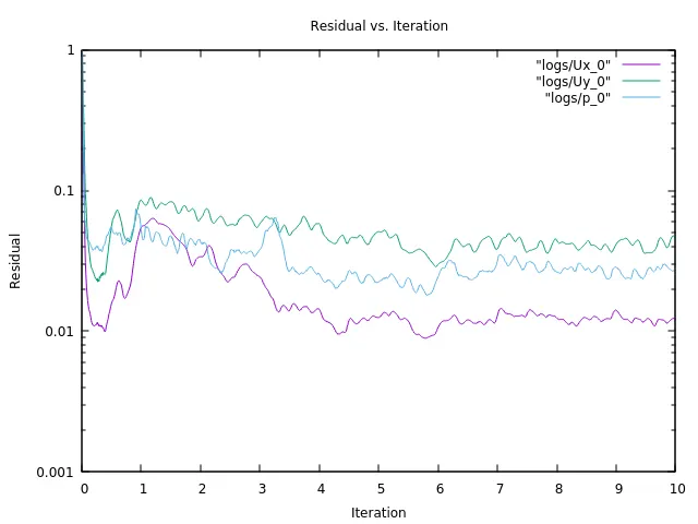
POST-POSTPROCESSING & RESULTS -
1. Mesh Generated -
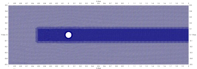
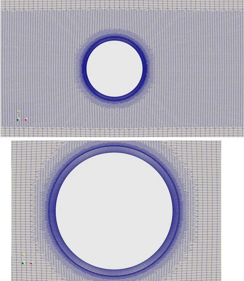
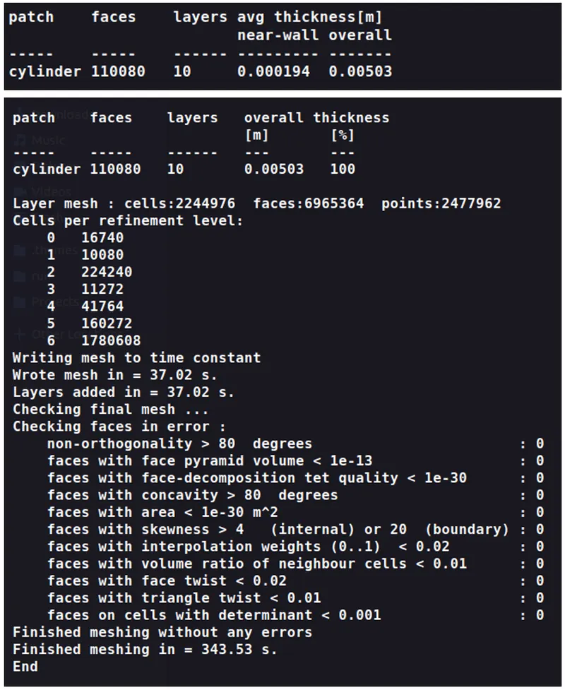
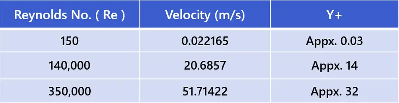
2. Outputs and Results for -
A) Re =150
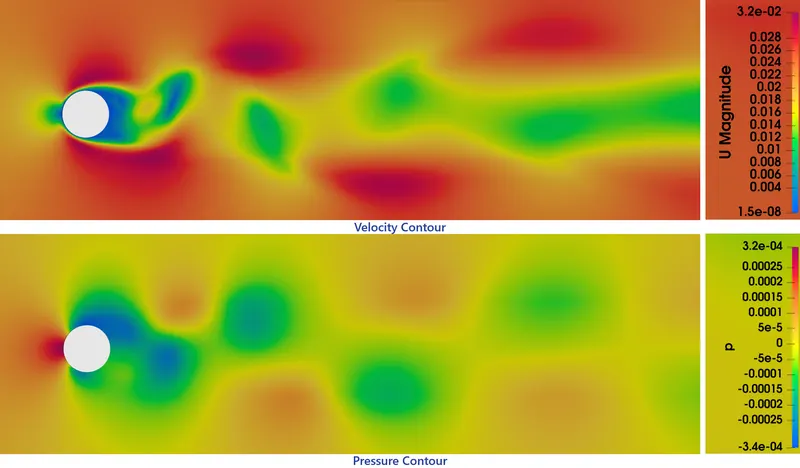
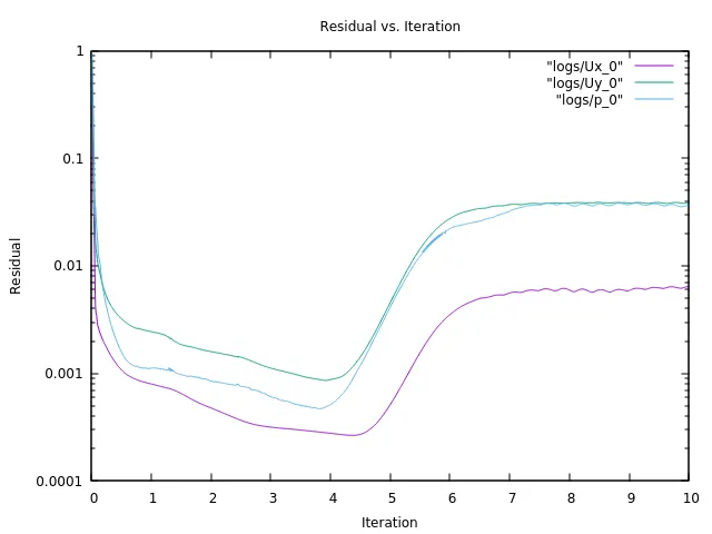
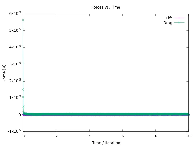
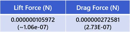
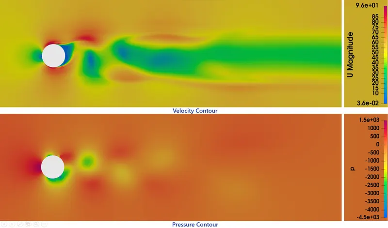
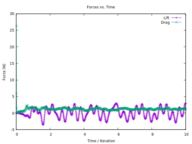
B) Re =140,000
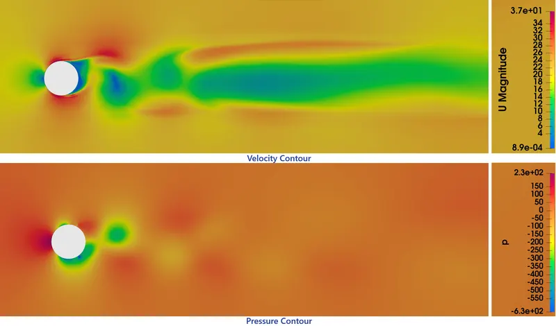
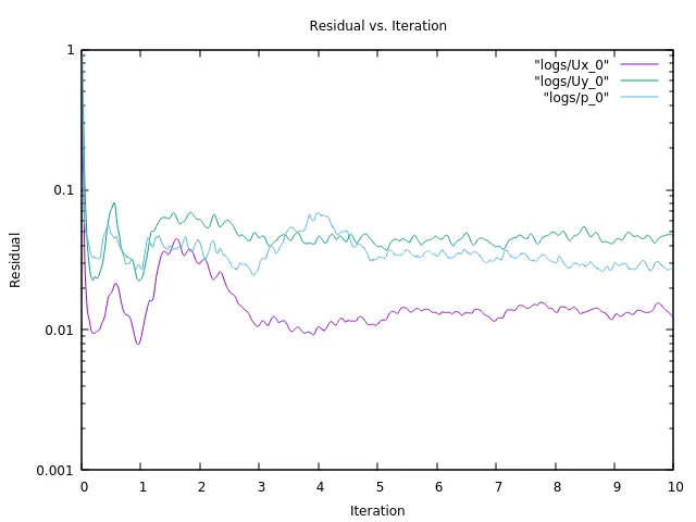
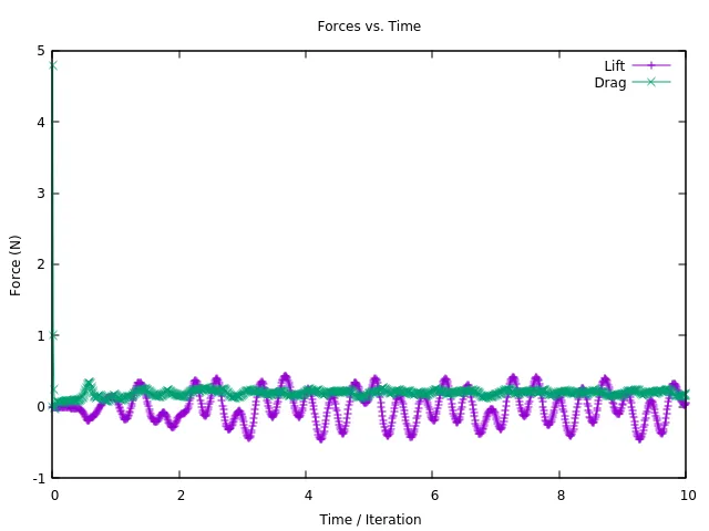
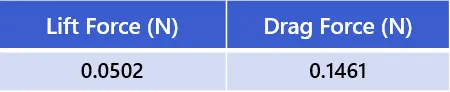
C) Re =350,000

3. Comparison with Experimental results -
Following is the Wind tunnel and experimental data from the research papers,
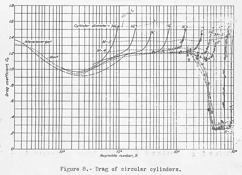
Taken Reference for the Re 150 ( Ref. [13] )

( Ref. [14] )
RESULTS :
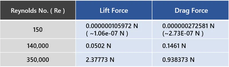
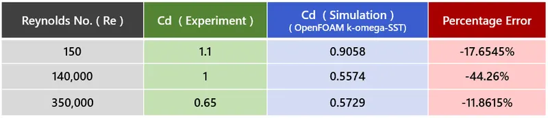
- Above there is the comparion of the results(Coefficient of Drag) with available experimental data with simulation data and calulating the percentage error.
- As we can see, that the `C_d` for the Reynolds no.s 150 and 350,000 the accuracy is quite near less than 20% compared to the Re = 140,000.
- One of the main reason for the higher error at Re = 140,000 is that it is lying iin transtion regime Partly laminar and then turbulent after the detachment. Therefore it's very difficult get accuracy at transition flow compared to fully laminar flow and the fully turublent flow. For the transition flow there is a turbulence model 'Transition K-Omega-SST' or 'K-Omega-SST LM' which introduces the concept of intermittancy. Transition SST model is based on SST k−ω transport equations coupled with two additional transport equations: one for intermittency 'γ' and the other for the transition Reynolds number 'Re θt'.
- The factors that can reduce error is meshing. Here, we have used a common mesh for all three flow regime, so as the Reynold no. goes up the first layer thickness is gonna reduce lower to satisfy Y+ condition inorder to capture near wall flows. In this project we have used snappy Hex mesh which is nice tool generate faster mesh with complex surface geometry, but one can create optimum structured or unstructered mesh as per the particular case inorder to get more accuracy.
- And coming to postprocessing, we can see the different contours for the different flow regimes, and can see vortex formations at the wake region and vortex shedding for the different flow speeds.
CONCLUSION :
As we have come to the concluding part of the project, we have successfully performed the simulation for the different flow regimes around the cylinder. We were able to see the generation of 2D-Snappy-Hex Mesh in openfoam for the cylinder and also adding the layer near wall zone. Postprocessing and visualizing the Kármán vortex street at 3 different reylond no. flows. At last, we saw and compared the accuracy of the results with the experimental results, and opens more area to work to see areas of accuracy improvents and doing the same with different turbulence models and compare the results.
REFERENCE :
- Flow instability and vortex shedding, https://youtu.be/xnr-yRcpnBs
- Vortex shedding and its control | Prof. S. D. Sharma, https://youtu.be/ahohd8ceGR4
- Dynamics and Control of Flow around Circular Cylinder, https://www.youtube.com/watch?v=pW0JfEBE9h8
- How to simulate a Flow around Cylinder - Von Karman in OpenFoam, https://youtu.be/YfK53PKpdgE
- Snappy hex Mesh tutorial, https://youtu.be/x5l9aEUm-LI
- Simulation setup, https://youtu.be/CuGYRYbB_Uw
- Lecture 7: Turbulence Modeling, Introduction to ANSYS Fluent, Ansys Tutorial. https://www.academia.edu/36090206/Lecture_7_Turbulence_Modeling_Introduction_to_ANSYS_Fluent
- Plotting Residuals in OpenFOAM; https://lordvon64.blogspot.com/2014/10/how-to-plot-residuals-in-openfoam.html
- Plotting Forces; https://github.com/openfoamtutorials/OpenFOAM_Tutorials_/tree/master/HowToPlotForces
- D.H Mudimeli; 'Boundary Layer Separation from a Circular Cylinder'; https://www.researchgate.net/publication/332963726_Boundary_Layer_Separation_from_a_Circular_Cylinder
- E Amalia, M A Moelyadi, M Ihsan; 'Effects of Turbulence Model and Numerical Time Steps on Von Karman Flow Behavior and Drag Accuracy of Circular Cylinder'; https://iopscience.iop.org/article/10.1088/1742-6596/1005/1/012012
- I. Rodríguez, O. Lehmkuhl, J. Chiva, R. Borrell, A. Oliva; 'On the flow past a circular cylinder from critical to super-critical
Reynolds numbers: Wake topology and vortex shedding'; https://doi.org/10.1016/j.ijheatfluidflow.2015.05.009 - John Stack; 'Compressibility Effects in Aeronautical Engineering'; https://ntrs.nasa.gov/citations/20070026133
- NACA TN 3083; Noel K. Delany and Norman E. Sorensen; 'Low-Speed Drag Of Cylinders Of Various Shapes.' https://ntrs.nasa.gov/citations/19930083675
- George W. Jones, Jr., Joseph J. Cincotta, Robert W. Wu Zker; 'Aerodynamic Forces on A Stationary and Oscillating Circular Cylinder at High Reynolds Numbers'; https://ntrs.nasa.gov/citations/19690007972