Structural Modelling using Etabs 2018
The architectural drawings for a G+7 residential building in zone 5 has been provided. The floor plan is the same for all 7 floor levels. Possible column positions have also been provided. Conceptualize a framing plan layout and then model the building in Etabs. The following architectural drawings have been provided:
- Typical floor plan – The location and thickness of the brick walls and the use of the
space (for estimating live load) can be obtained from this plan - A building section through the staircase and lift core is provided
- Parking layout in the ground floor – the column/shear wall arrangement must not
obstruct entry/exit of vehicles.
The following loadings are to be taken into account: - Brickwall made of AAC blocks
- Finishes – floor tiles of 75 mm thickness
- Live loads as per IS 875 part 2
- Water tank of 20 KL above the staircase at Mumty level
- Lift Machine room at mumty level above lift core
The structural model must comply with provisions of IS 1893 and IS 13920.
Run a modal response spectrum analysis and check analysis results of the etabs model for inter-storey drift requirements, vertical & planar irregularities, minimum shear wall requirements, maximum axial load ratio for column and shear walls, effective moment of inertia for beams
and columns etc.
Aim – to model an building with all seismic considerations, based on the architectural inputs. And to make the structural model must be comply with provisions of IS 1893 and IS 13920.
Procedure –
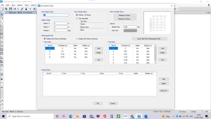
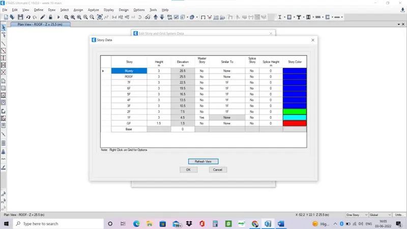
Open ETABS and plan the grid and storey according to the given architectural plan.
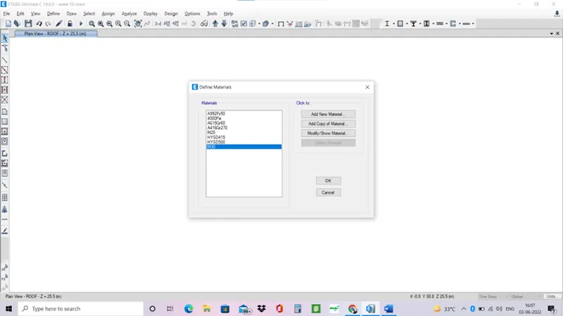
Now the material properties are defined.
Grade of concrete = M30
Longitudinal reinforcement = HYSD500
Shear reinforcement = HYSD415
Now define section properties.
Column = 400 x 400 and 400x600 and moment of inertia at 0.7
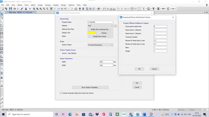
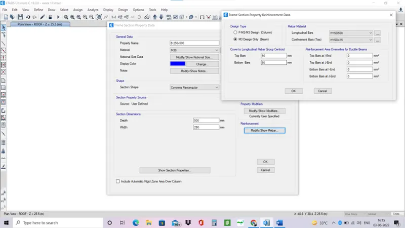
Beam = 250 x 500 and moment of inertia at 0.35
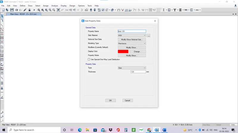
Slab = 120mm and 175mm
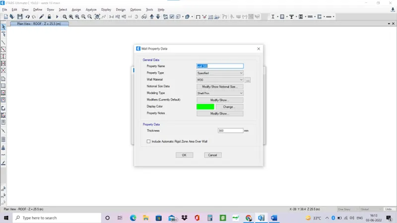
Shear wall = 300 mm
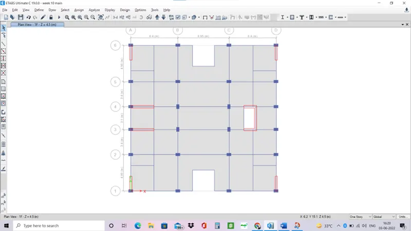
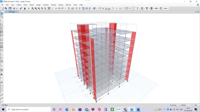
Column, beams, slabs and shear wall is placed accordingly to the given architectural plan.
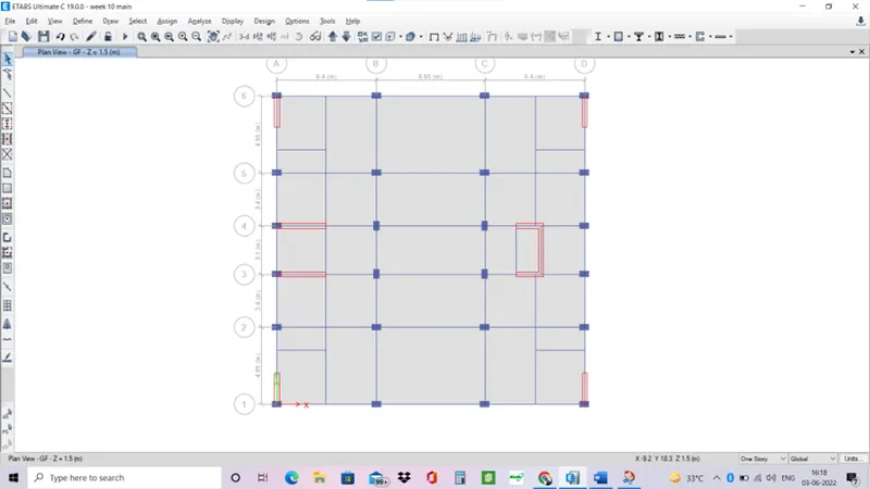
Make changes according to given elevation ctrl+R (replicate) and ctrl+m (move) and edit option to break sections and shells.
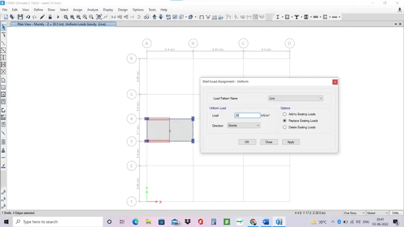
Now assign loads on the building.
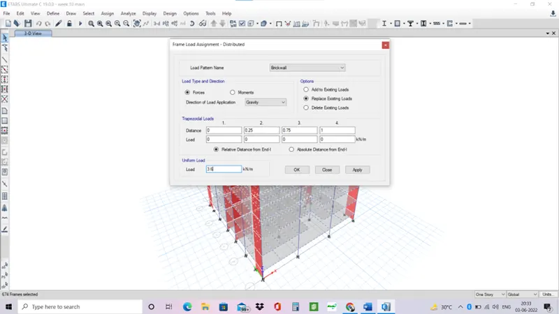
Apply brick wall loads to all the beams 3.6 kN/m
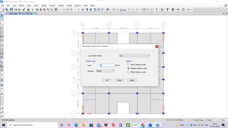
Apply live load for rooms, kitchen, bathroom etc for 2 kN/m and 3kN/m for passage and balcony stairs etc.
Apply floor finish load of 1.5 kN/m
And, for water tank on top for 20 kN/m on mumty level.
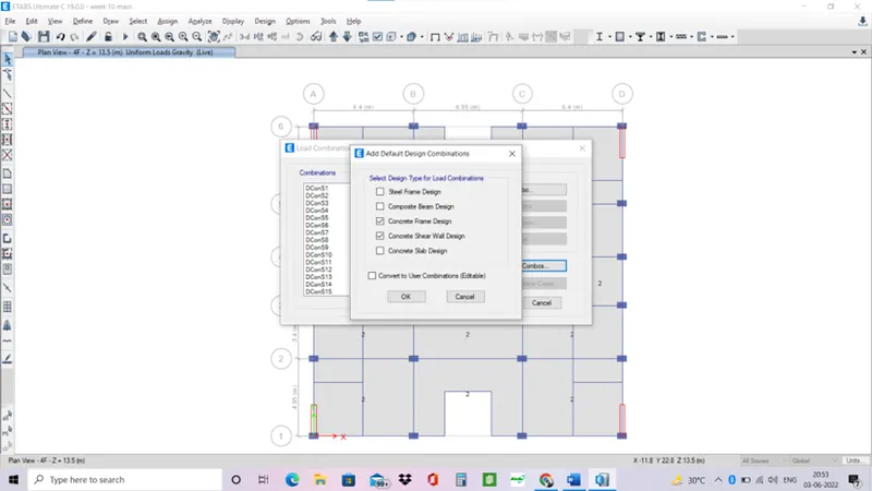
Add load combinations for concrete frame design and concrete wall design.
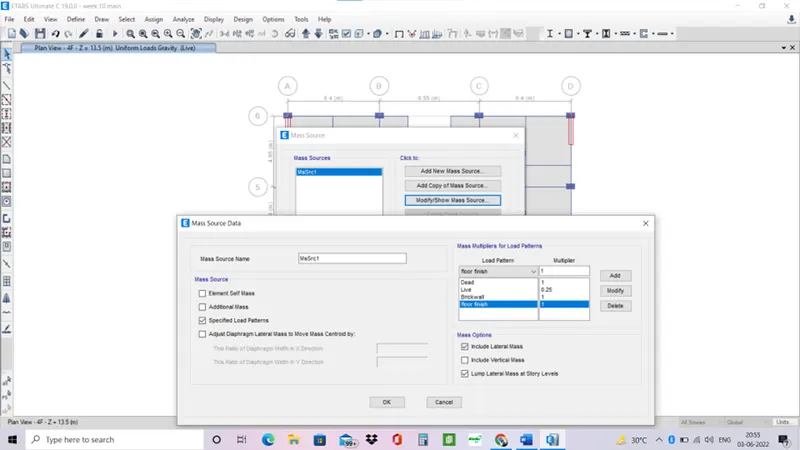
Add mass source
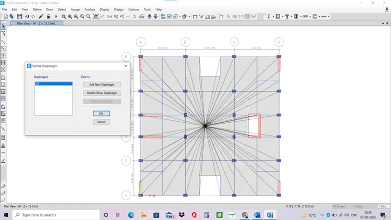
Add diaphragm to the model
Add response spectrum for x and y direction in load cases.
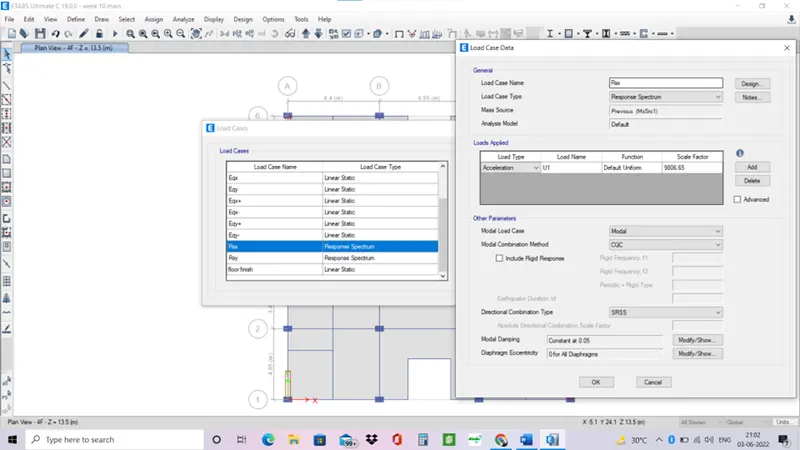
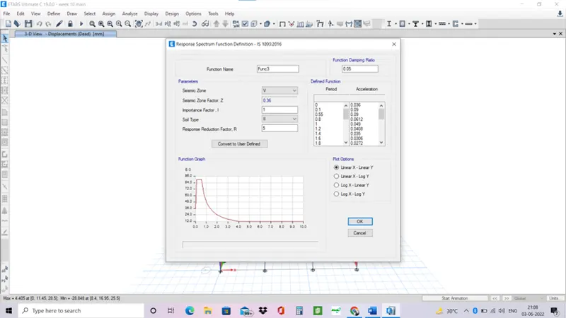
Response spectrum
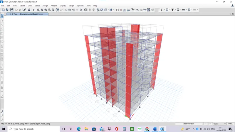
Run the analysis on the model and deformed shape is obtained.
Check the model with compliance from IS 1893 and IS 13920.
Results
- Modal mass participation for first 3 model dominates at least 65% in both x and y direction.
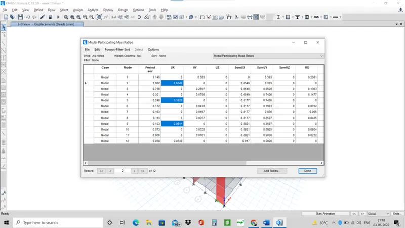
In x direction it easily satisfies wheras in y direction it just barely reaches 66% but okay.
- 10% difference in mode 1 and mode 2
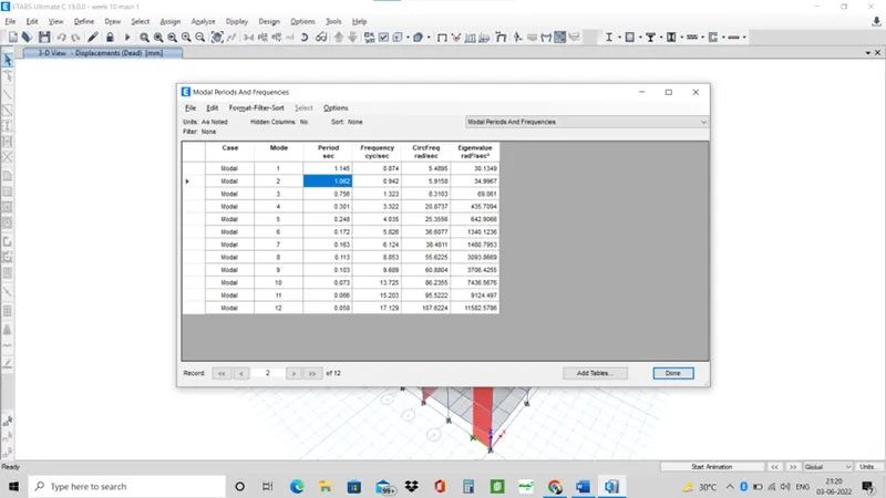
Not satisfied therefore changes are to be to done to satisfy this.
- Principal modes be greater than torsional mode
Mode 1 and mode 2 are greater than mode 3 therefore satisfies.
- Inter storey drift ratio limited to 0.004 in both x and y direction.
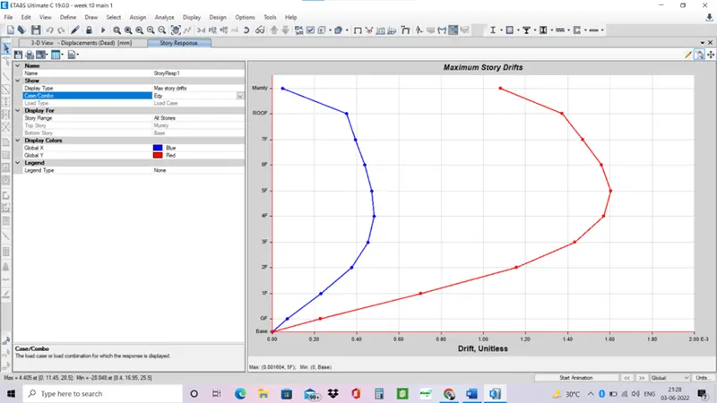
As we can see the drift ratios are less than 0.004 in both direction therefore satisfies.