Structural Modelling using Etabs 2018
AIM :
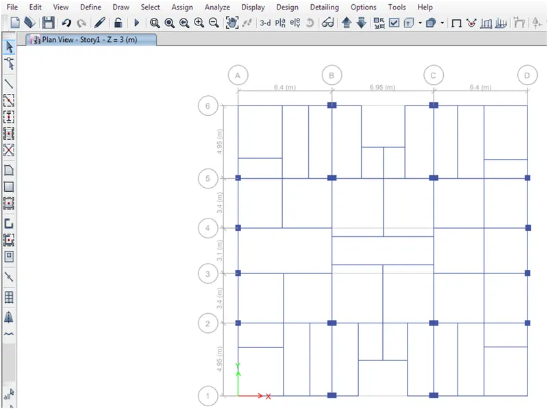
The architectural drawings for a G+7 residential building in zone 5 has been provided. The floor plan is the same for all 7 floor levels. Possible column positions have also been provided. Conceptualize a framing plan layout and then model the building in Etabs. The following architectural drawings have been provided:
Introduction : Etabs help us to design and detailing the building elements like beam , column , shear wall and other parameters
Procedure :
-
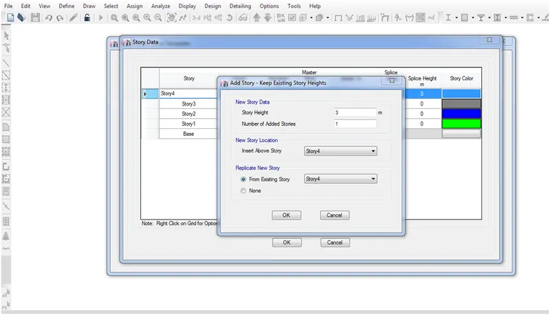
Change the number of story of building as 8 and 1 terrace
-
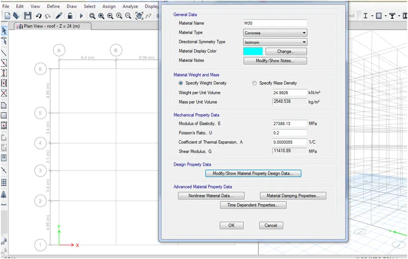
Material define go to define material property add new material click on it and M30 material
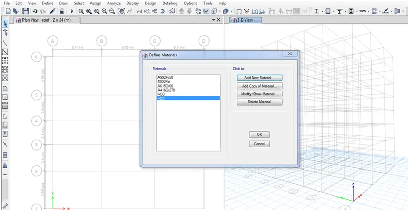
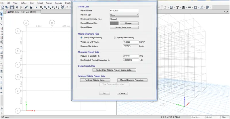
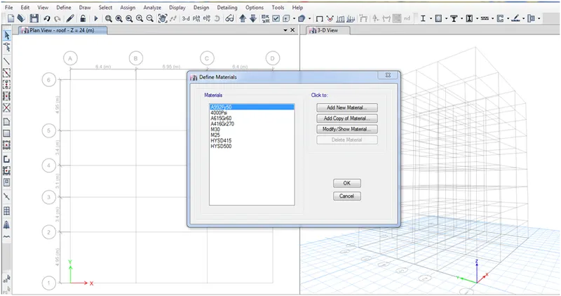
- Rebar material fe415 and fe500
- Define beams and column size of column are 400 x 400 and 400 X 600
- Size of beam is 300 X 500 and 250 x 450
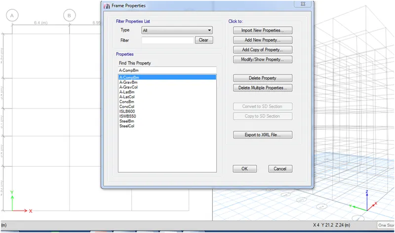
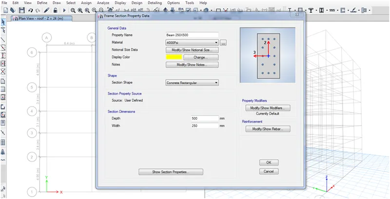
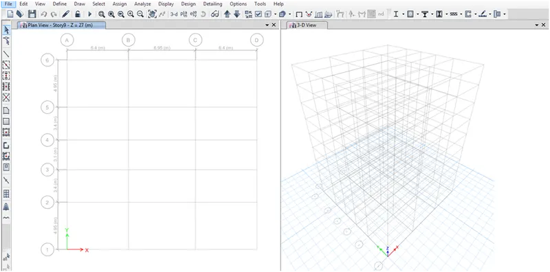
- Depth of beam is 500 and 250 shown in the above pic
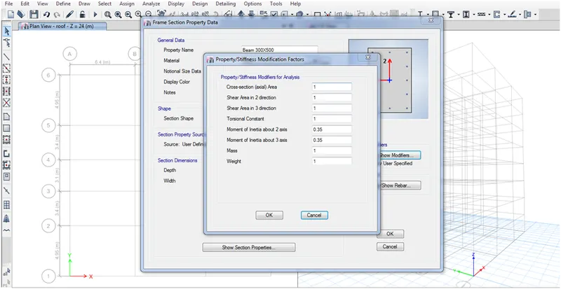
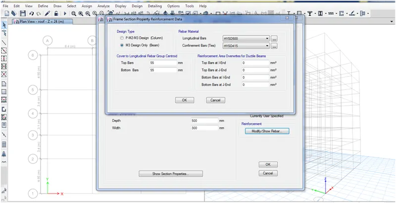
- For the main bar the dia of bar is fe500 and fe415 for the shear tensile
- Cover will be 55 mm on top and bottom will be more conservative on the main bar
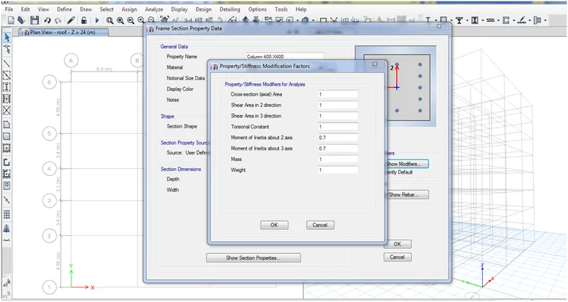
- For column we need to provide the mi as 0.7 or 70 %
- And cover for the column are 40 mm
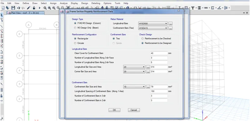
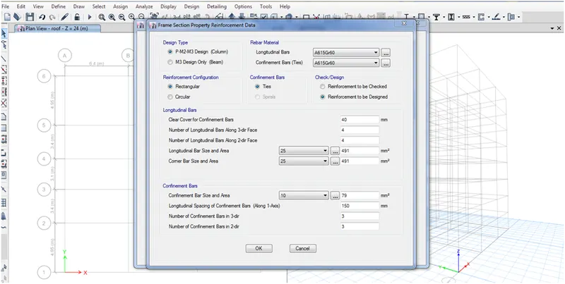
- Add main bar as 25 mm and corner bar as 25 mm and and clear cover as 40 mm and spacing of confinement bar as 100 mm spacing
- Number of confinement bar in direction 3 as 2 because the dimension of column as 400 so min 300 mm spacing are given in confinement bar
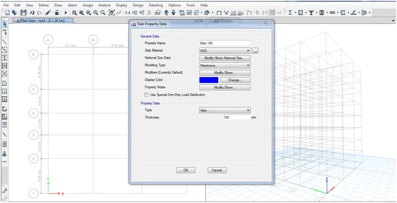
For the slab the modeling type membrane and thickness is 150 mm
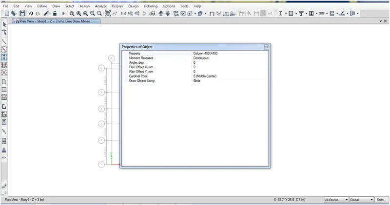
- For column at the column 400 X 400 are to added so that the corner or phiryphery the load are less so need lees dimesnsion column for all stores
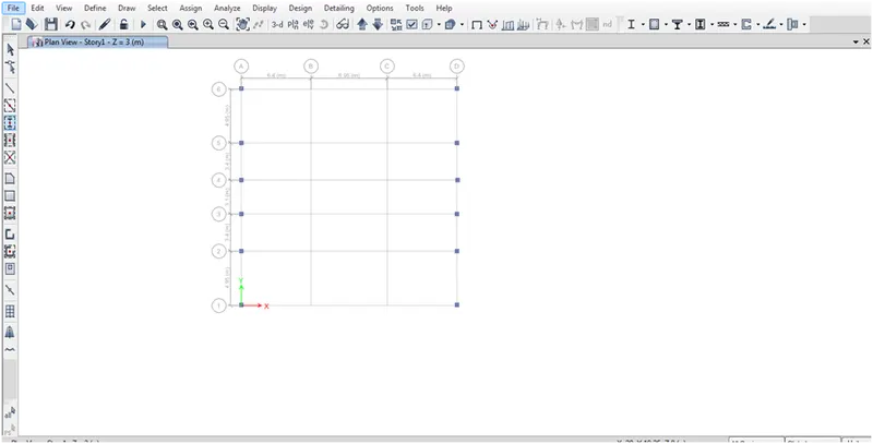
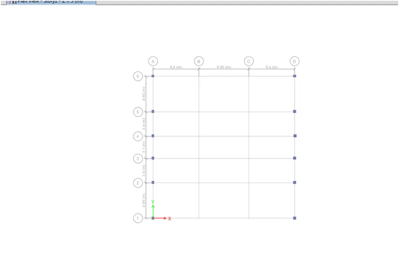
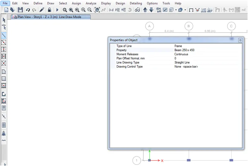
Select beam as 250X450 mm in by selecting the beam draw
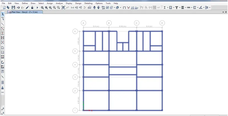
- Floor secondry beam command replicate CTRL + R
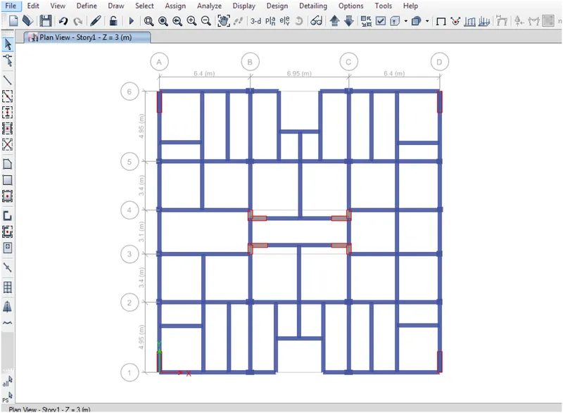
- shear wall draw by go to draw drop down draw wall and select the type of wall
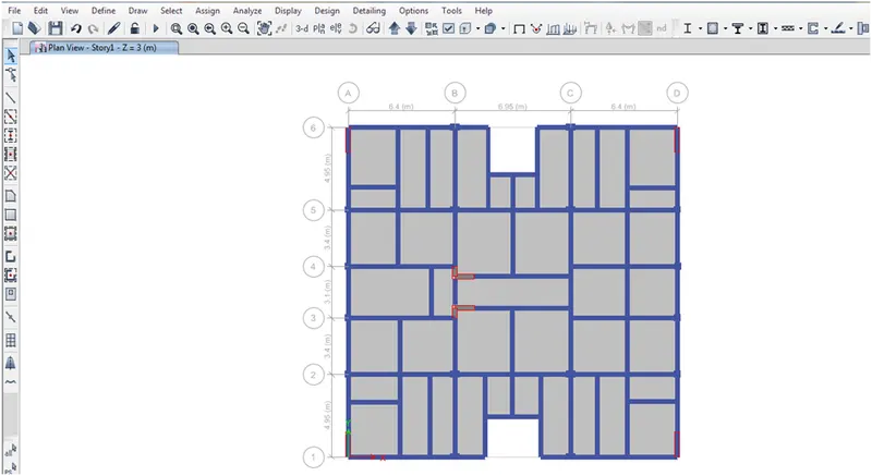
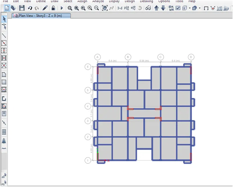
- Drawing cantilever beam by using mirror command
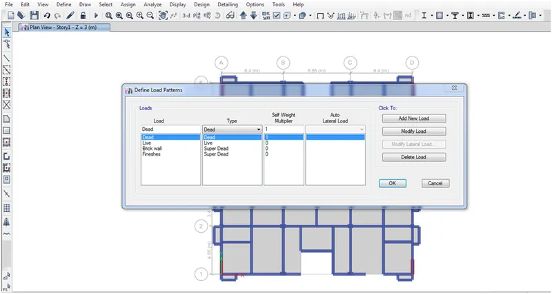
- Go to define drop down and load pattern
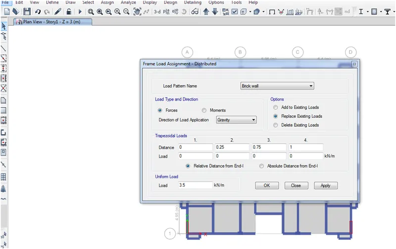
- Assign , frame load, Distributed load select load pattern and load as 3.5 KN
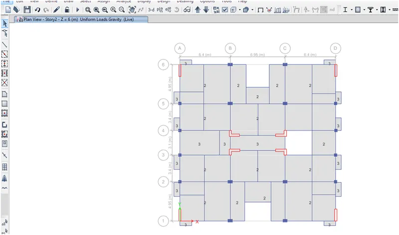
- For the residential building the load at the balcony and the corridor are to be add 3 kn as per IS 875 part 2 and remaining room are 2 KN
- Go to Assign shell load and load type select live load and 3 kN and 2 KN
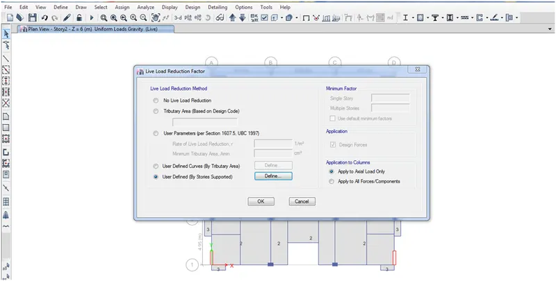
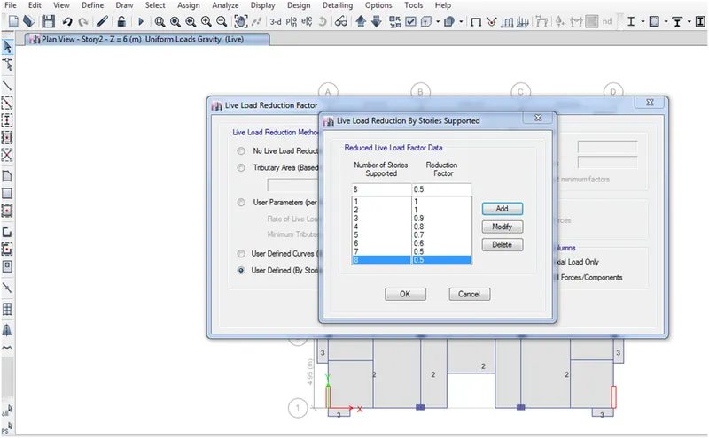
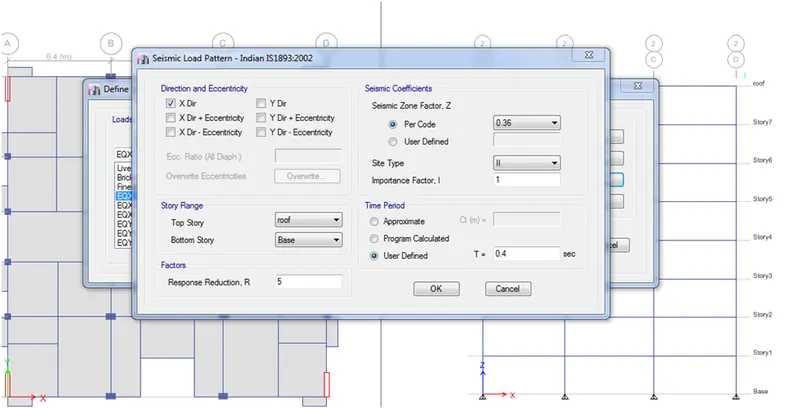
T =0.09/ROOT H
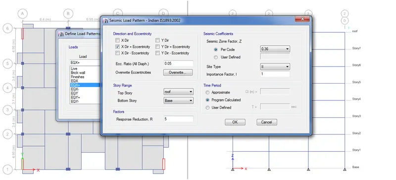
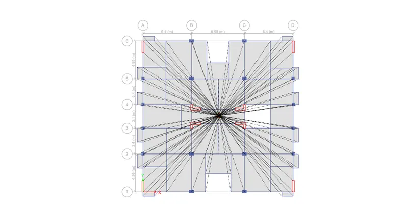
- Diaphram go to select select by object and floor , assign shell diaphragm D1 ok
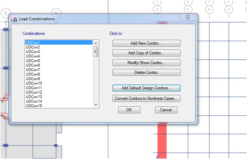
- Load combination as user defined for concrete and shear wall
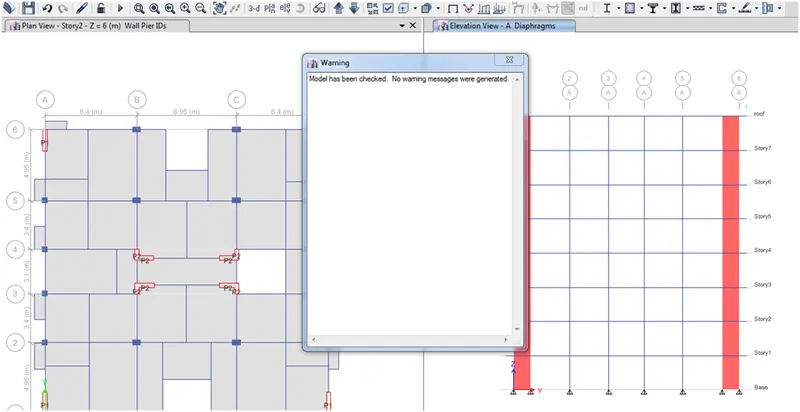
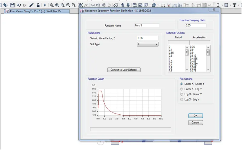
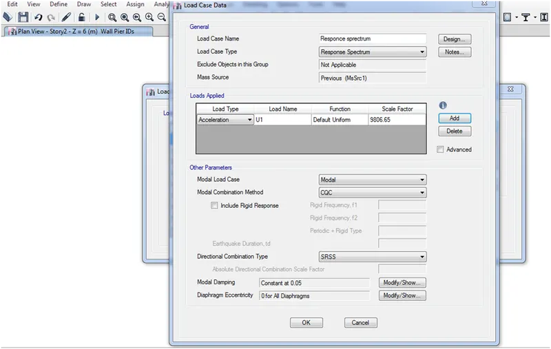
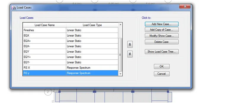
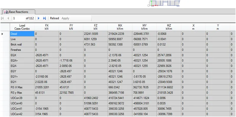
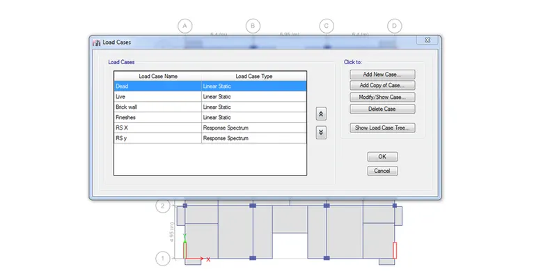
- Here response spectrum is almost equal to the seismic zone so no need to increase the scale factor
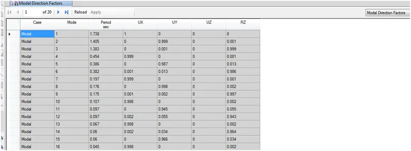
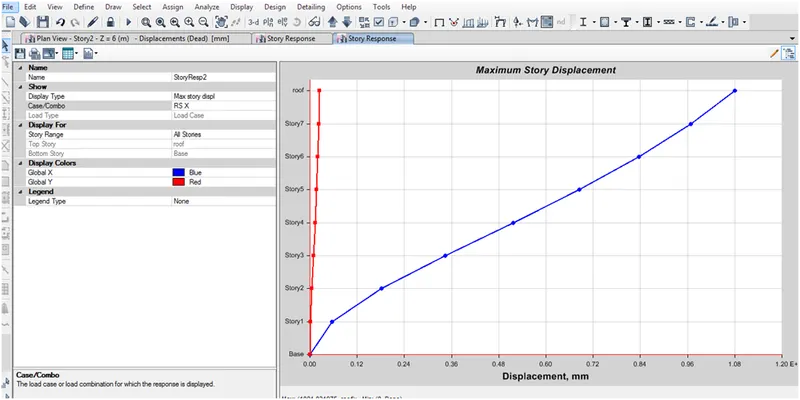
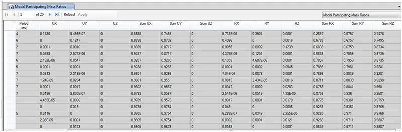
- Max 15 mode are sufficient for the this is about the 93 percent
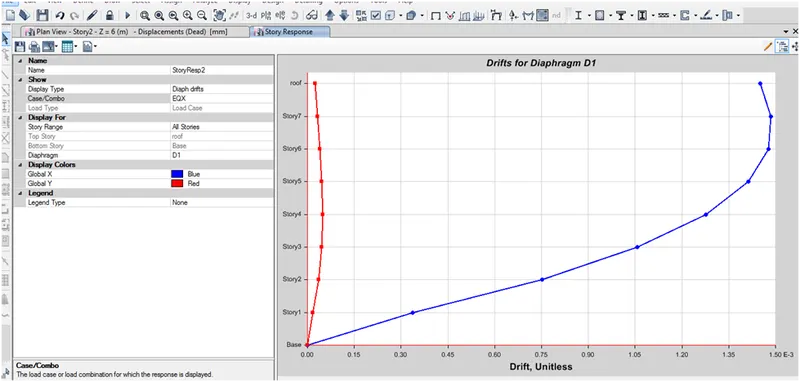
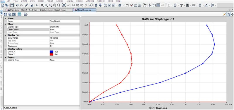
- Before adding shear wall to the lift portion the drift portion Is about the 8 but after adding wall it reduced to 1.5