Structural Modelling using Etabs 2018
AIM:- to model the structure confirming to the IS CODE 1893 and IS CODE 13920 for the given architectural plan of G+7 residential buidling
GIVEN DATA:-
- drawings of the typical floor plan, section view of the building, and parking layout
- a brick wall made of AAC blocks
- finishes- floor tiles of 75mm thickness
- water tank above the staircase at mumty level
- machine room above the lift core
- live load should be considered as per IS 875 part 2
ETABS MODELING
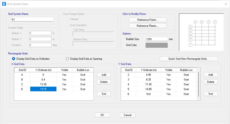
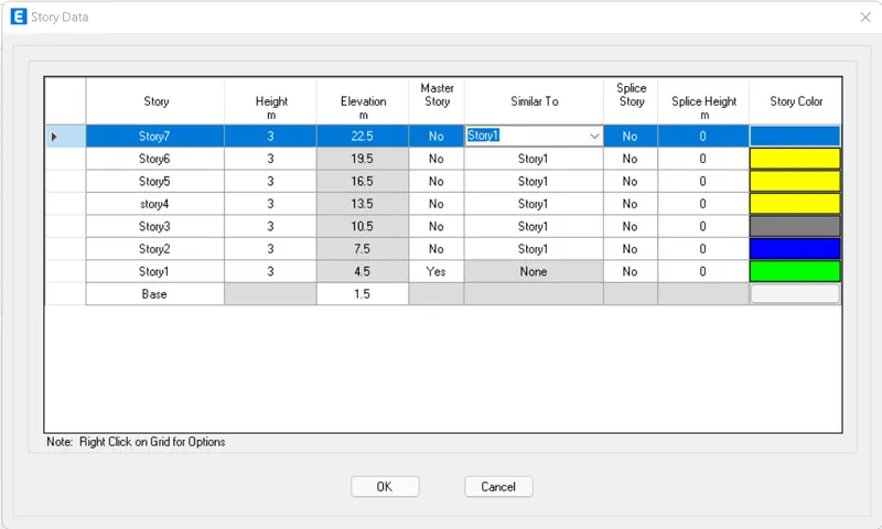
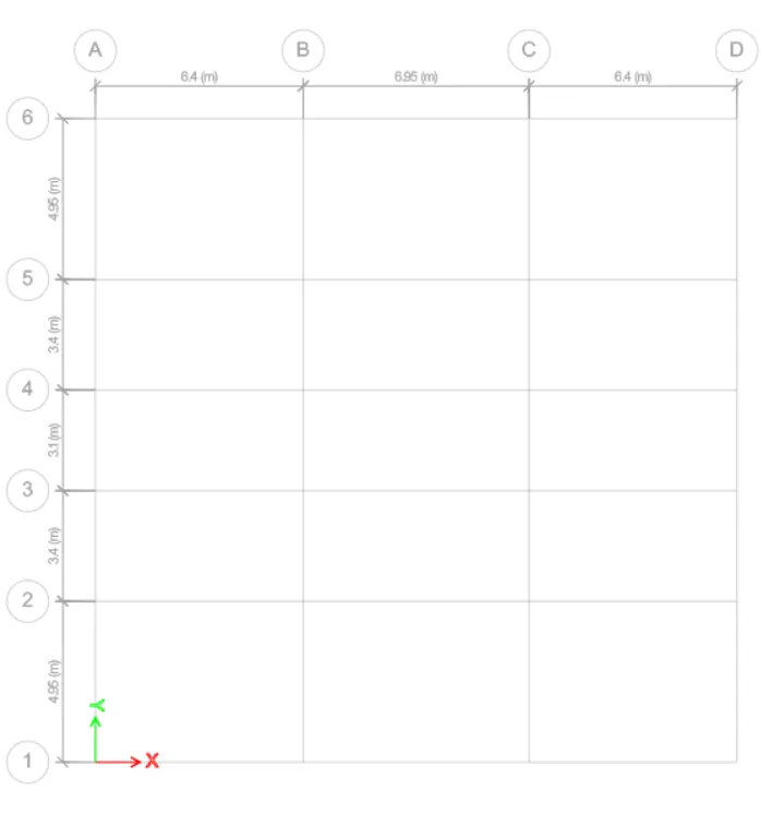
TO ADD GRID AND STORY DATA
- open etabs > go to a new model
- click on edit grid and story data
- click on custom grid data to add grids
- click on custom story data to add elevation details
- then click on ok
TO DEFINE MATERIAL PROPETIES, SECTION PROPETIES
- go to define> material properties
- click on add new property
- add a grade of concrete like M30
- add a grade of longitudinal reinforcement as HYSD500
- add a grade of shear reinforcement as HYSD415
- click on ok
- then go to define>section properties>frame sections
- click on add new property
- add the size of the beam as 300 X 550 with inertia as 35%
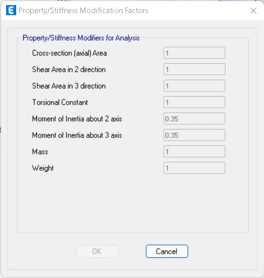
- add the size of the column as 450 x 600 with initial inertia as 70%
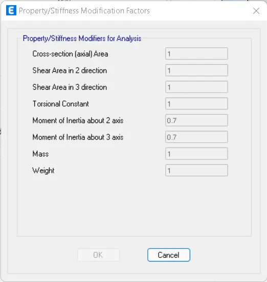
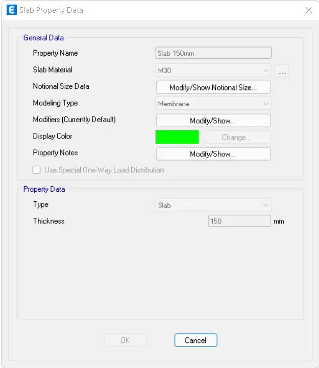
- Click on define>section properties>shell sections
- add the thickness of the slab as 150mm
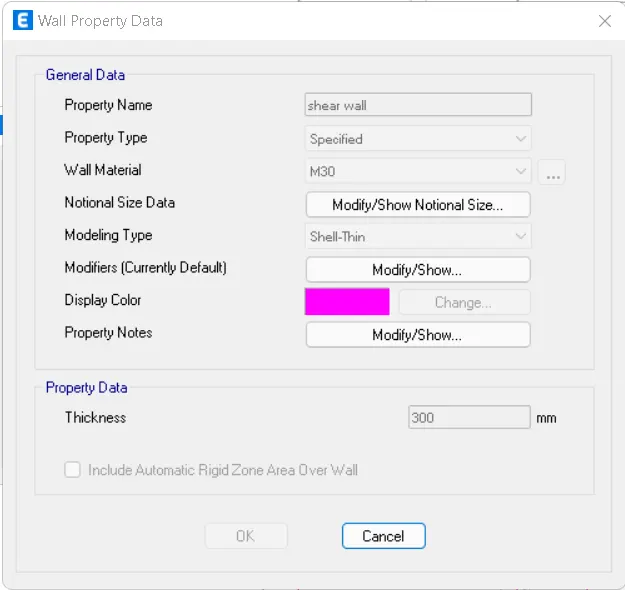
- go to define>section properties>wall sections
- define the thickness of the shear wall as 300mm
- click on ok
TO DEFINE LOAD PATTERNS AND COMBINATIONS
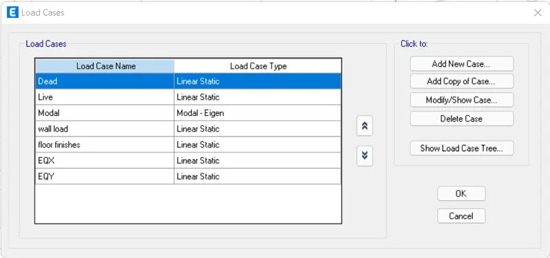
- go to define>load patterns
- add dead load, live load, wall load, floor finishes, and earthquake loads
- then go to load combinations
- click on add default design combination
- select concrete frame design
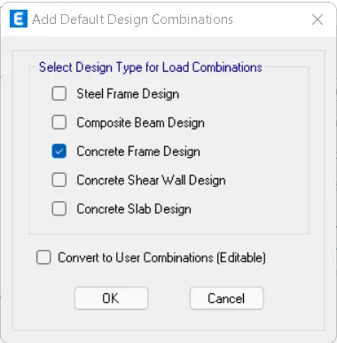
- click on ok
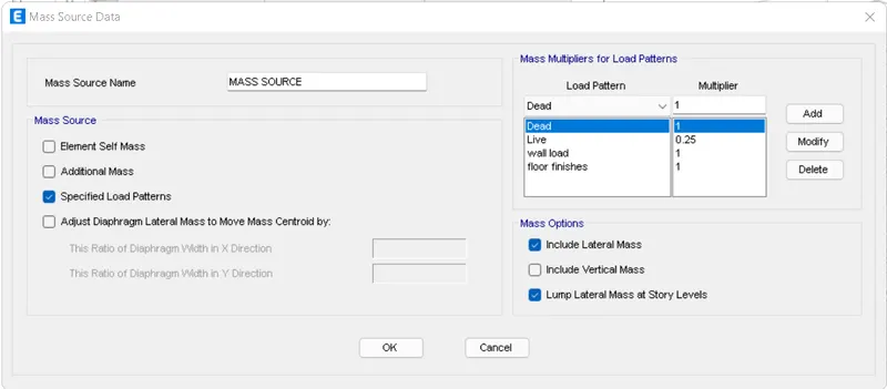
- add mass source also
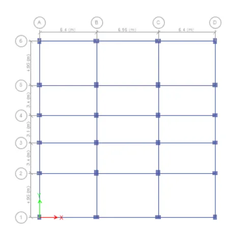
TO MODEL THE STRUCTURE ADDING BEAMS, COLUMNS AND ORIENTING THE COLUMNS
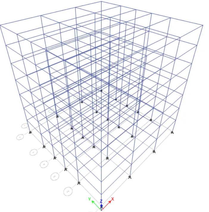
TO MODEL THE STRUCTURE BY ADDING SECONDARY BEAMS USING REPLICATE
- to copy the beam element
- go to edit > replicate
- select the element and specify the distance to add the secondary beam
- then divide/break the connecting beam
- to divide/break the beam
- go to edit> edit frames
- click on divide frames
- select break at intersections with selected frames and joints
- Click on apply and oK
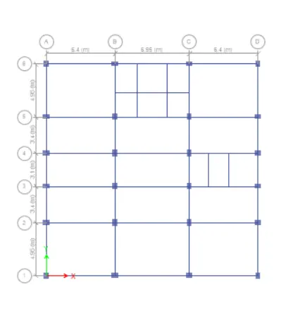
TO ADD SHEAR WALLS
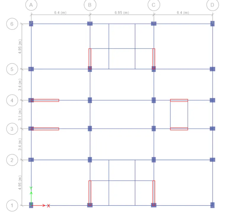
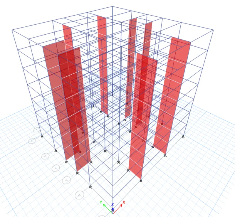
add the shear walls to the model with a thickness of 300mm such that they are positioned symmetrically doesnot exceed the 0.2% of the floor area of the plan and doesnot disturb the architechtural plan and access to the parking
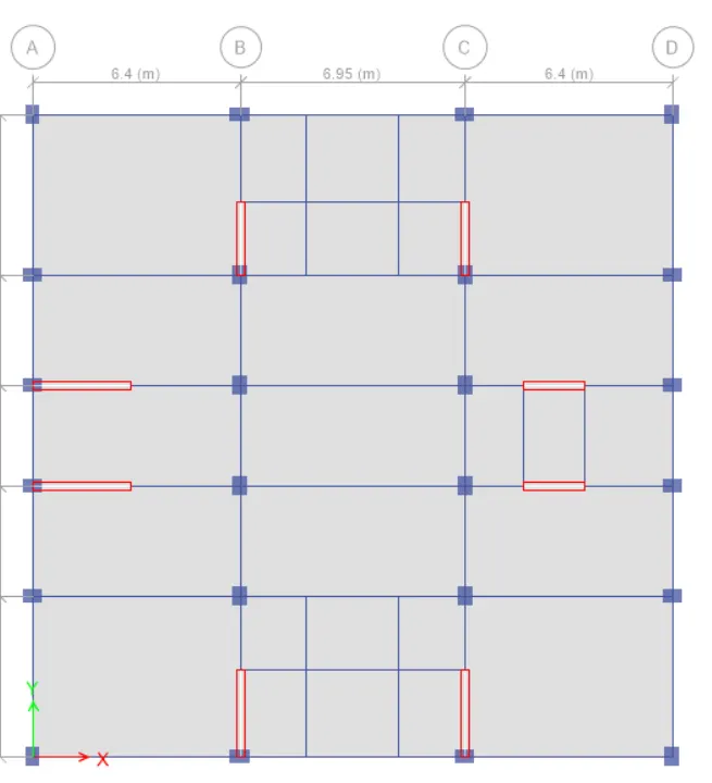
TO ADD SLAB PANELS AND ALSO EDIT THE PANELS TO CREATE OPENINGS
- add slab element to all the panels
- then select the slab element and all other frame sections in a panel
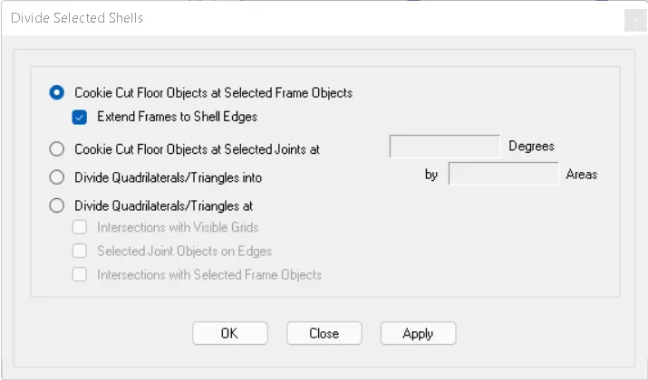
- go to edit> edit shells
- click on divide shells
- select on cut floor objects and selected frame objects
- Click on apply and okay
- then the slab element is divided as per the frame object
go to edit
select edit shells>divide shells
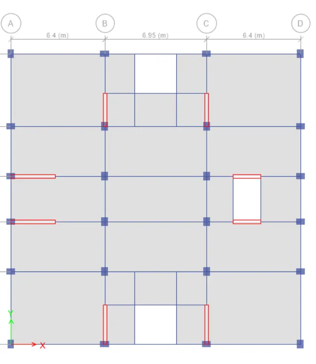
TO ASSIGN LOADS TO THE MODEL
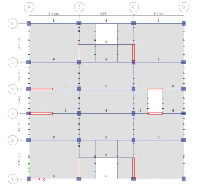
- select all the beam elements
- go to assign>frame loads
- specify the wall load as 6kn/m^2 for the AAC blocks
- click on ok
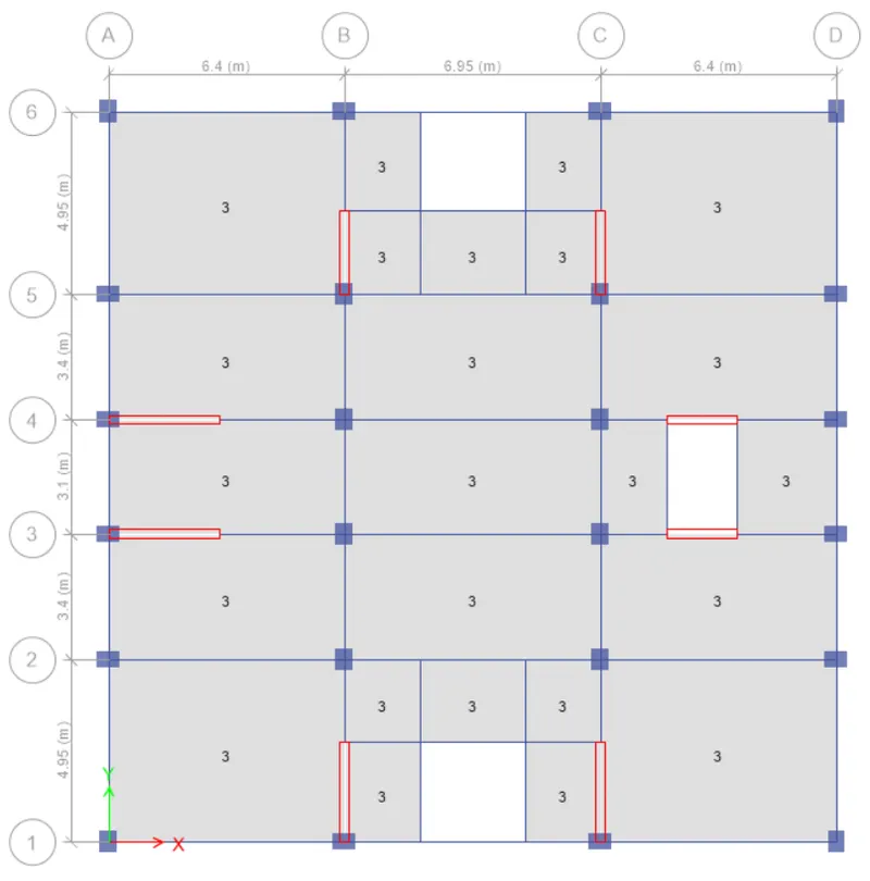
- select all the slab panels
- go to assign>shell loads
- specify the live load as 3kn/m^2 for the residential plan as per IS 816
- specify the load for the floor finishes as 1.25kn/m^2
- assign diaphragms
- click on ok
TO PERFORM ANALYSIS AND DESIGN THE MODEL
- click on run analysis
- after the analysis has been completed
- go to concrete frame design
- click on start design check
- after the design has been done
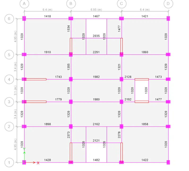
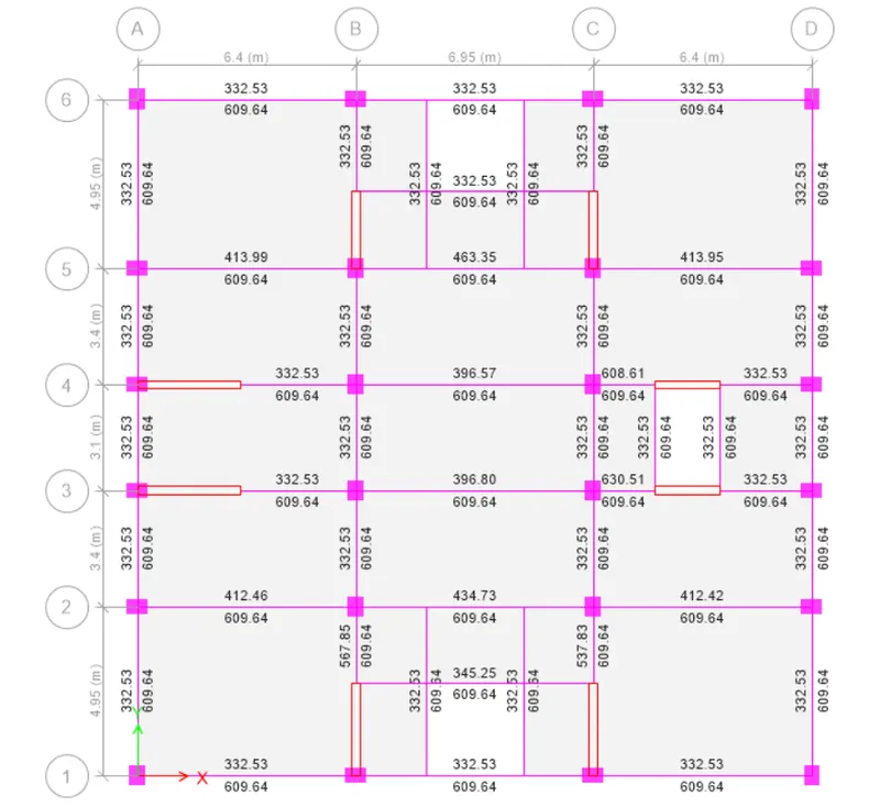
- go to display design information to view longitudinal and shear reinfocement details
Longitudinal reinfocement details
Shear reinforcement details
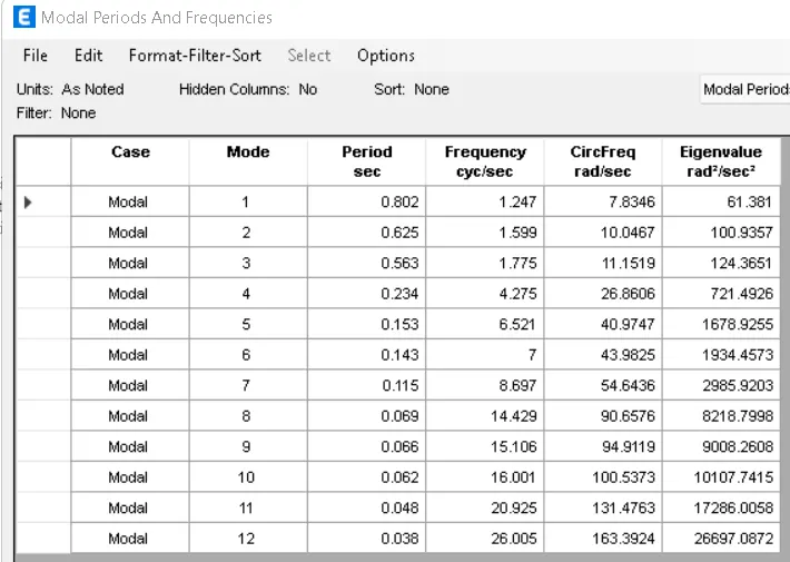
Modal period and frequency table
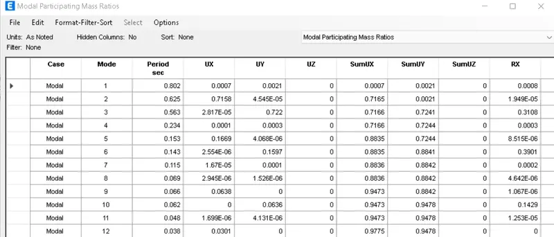
Modal mass paticipating ratio table
TO VIEW RESPONSE SPECTRUM
to go display
response spectrum
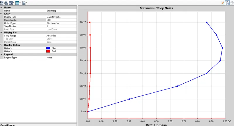
the below mentioned graph is max story drifts for the corresponding EQX
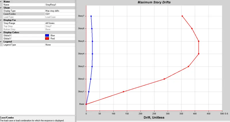
the below mentioned graph is max story drifts for the corresponding EQY
RESULTS:-
- acheived 90% of the modal mass paticipation within the first 3 modes
- principal modes are greater than torsional mode
- inter story drifts are within the limits
- mode 1 and mode 2 differ by 10%