Structural Modelling using Etabs 2018
The architectural drawings for a G+7 residential building in zone 5 has been provided. The floor plan is the same for all 7 floor levels. Possible column positions have also been provided. Conceptualize a framing plan layout and then model the building in Etabs. The following architectural drawings have been provided:
- Typical floor plan – The location and thickness of the brick walls and the use of the
space (for estimating live load) can be obtained from this plan - A building section through the staircase and lift core is provided
- Parking layout in the ground floor – the column/shear wall arrangement must not
obstruct entry/exit of vehicles.
The following loadings are to be taken into account: - Brickwall made of AAC blocks
- Finishes – floor tiles of 75 mm thickness
- Live loads as per IS 875 part 2
- Water tank of 20 KL above the staircase at Mumty level
- Lift Machine room at mumty level above lift core
The structural model must comply with provisions of IS 1893 and IS 13920.
Run a modal response spectrum analysis and check analysis results of the etabs model for inter-storey drift requirements, vertical & planar irregularities, minimum shear wall requirements, maximum axial load ratio for column and shear walls, an effective moment of inertia for beams
and columns etc.
AIM: To model and analyze the G+7 building using ETABS by applying Load cases and combinations for the given floor plan drawings.
PROCEDURE:
Step1: First set the Grids and Story data according to the given information.
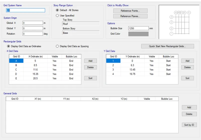
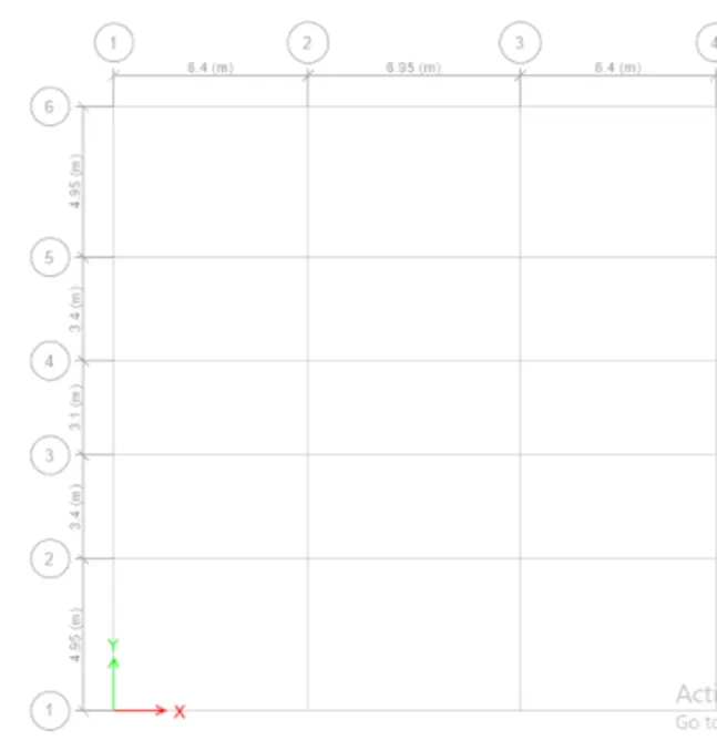
Step2: Now define the concrete material, steel material.
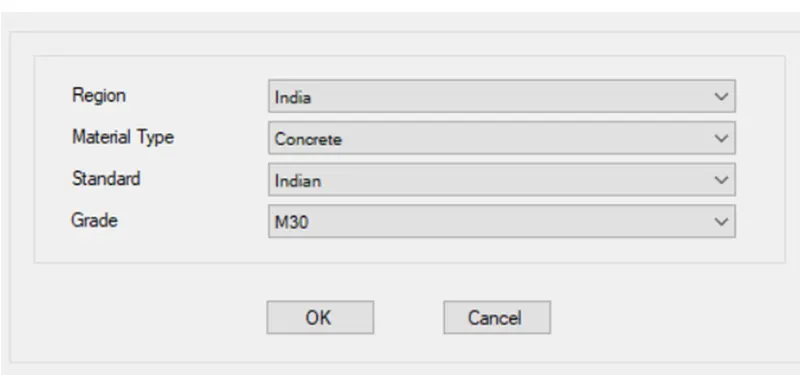
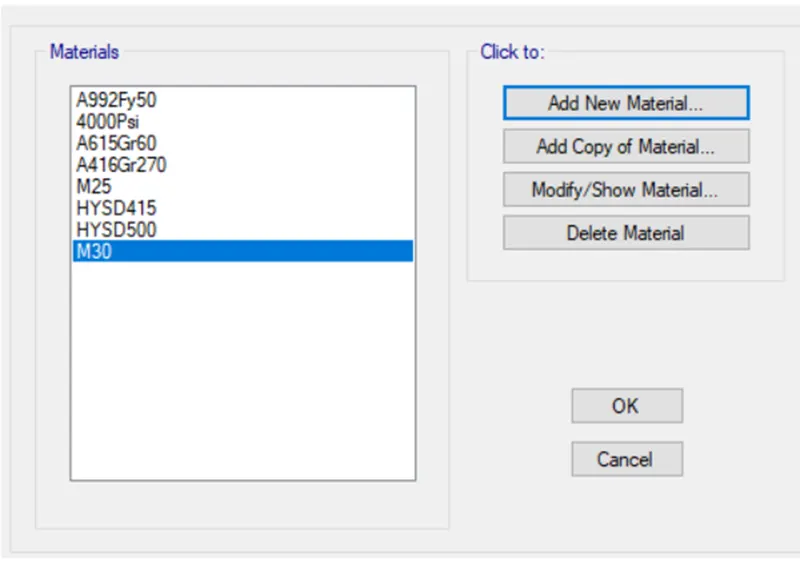
Step3: Now define the section properties.
Beam- 250x500mm
Column- 400x400mm
Column – 300x550mm
Slab- 125mm
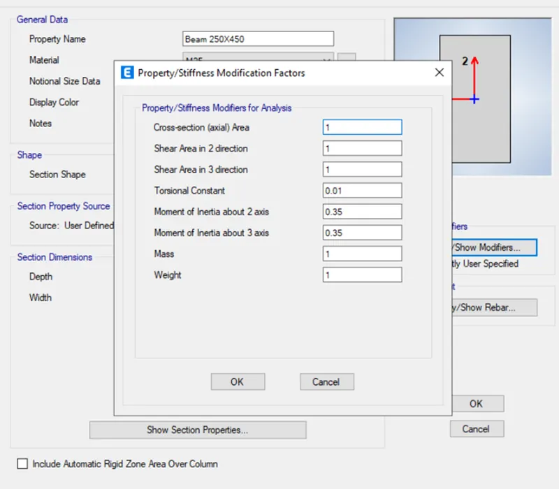
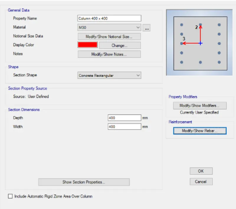
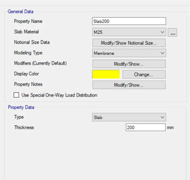
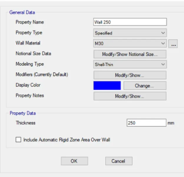
Step4: Now define the wall property of thickness 250mm.
Step5: Now place the defined columns and beams at appropriate places according to the plan given using quickdraw column and beams tools accordingly.
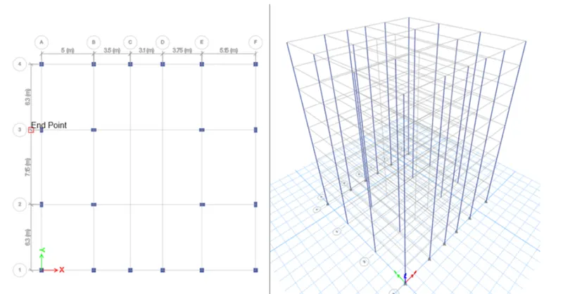
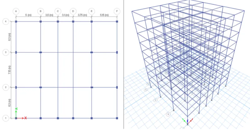
Step6: Now draw the slab & also the shear wall according to IS codes.
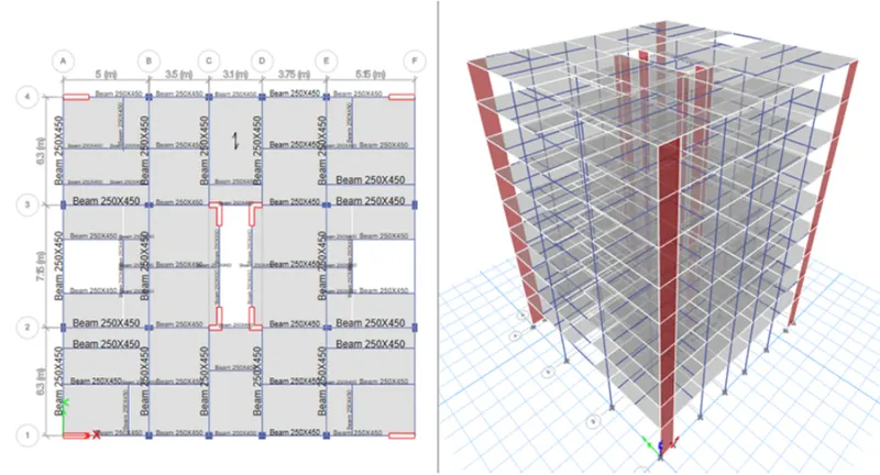
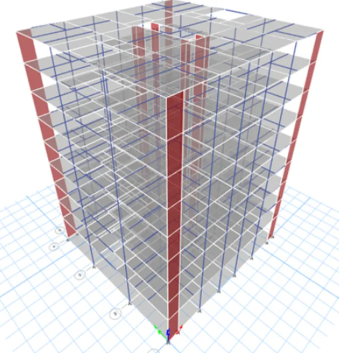
Step7: Now define the load cases.
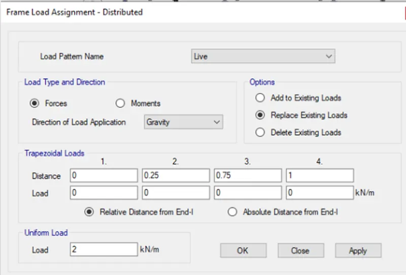
Dead Load, Live load of 2kN/m^2, a Brick load of 3.5kN/m^2, Floor finish load of 1.2 kN/m^2.
And apply each load to the model accordingly.
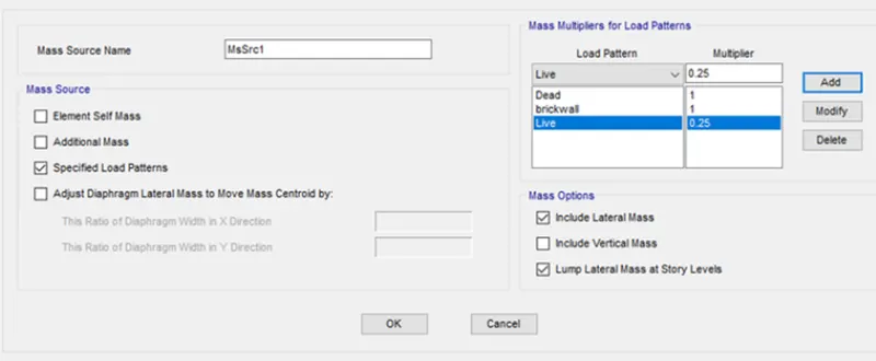
Step8: As per table 10 the mass source of the live load is up to 3kN/m^2. So we can add a mass source of 0.25 for live load.
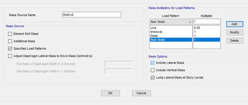
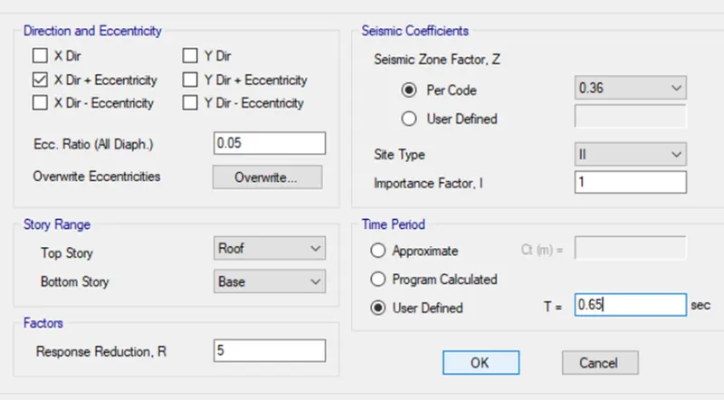
Step9: Define the earthquake loads as EQX and EQY.
Step10: Now define the diaphragm to the model.
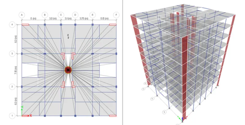
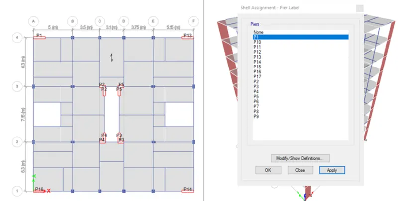
Step11: Now the shear walls are pier labeled with the appropriate number.
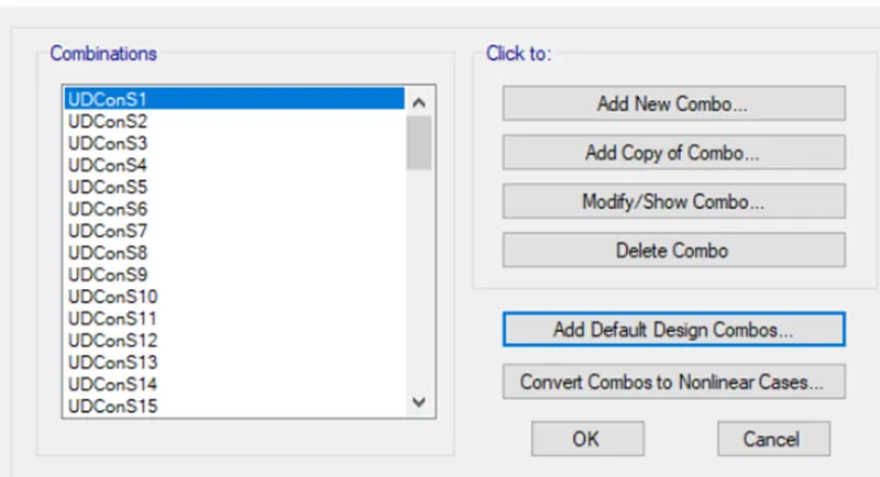
Step12: Now define the load combinations for the model.
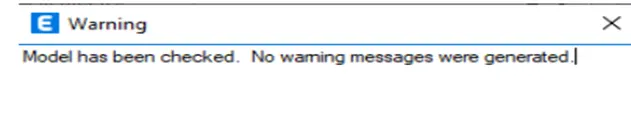
Step13: Check the errors and warnings in the model.
Step14: Add the load cases with response spectrum in both X & Y directions.
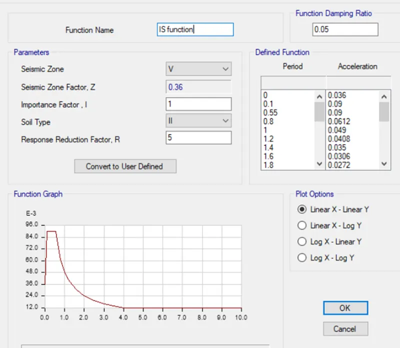
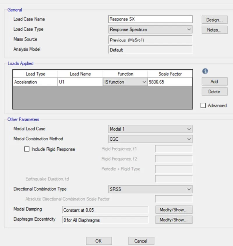
Step15: Now run the analysis.
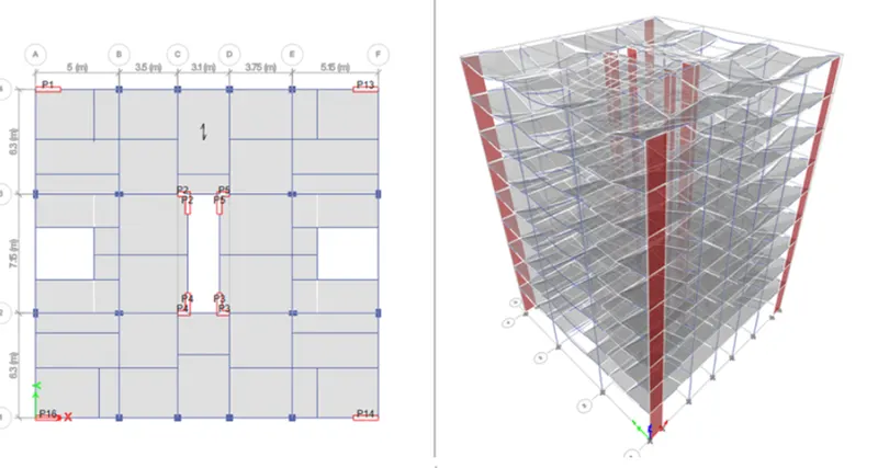
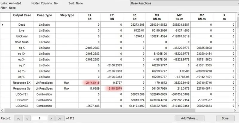
Step16: Check the base reactions after running the analysis.
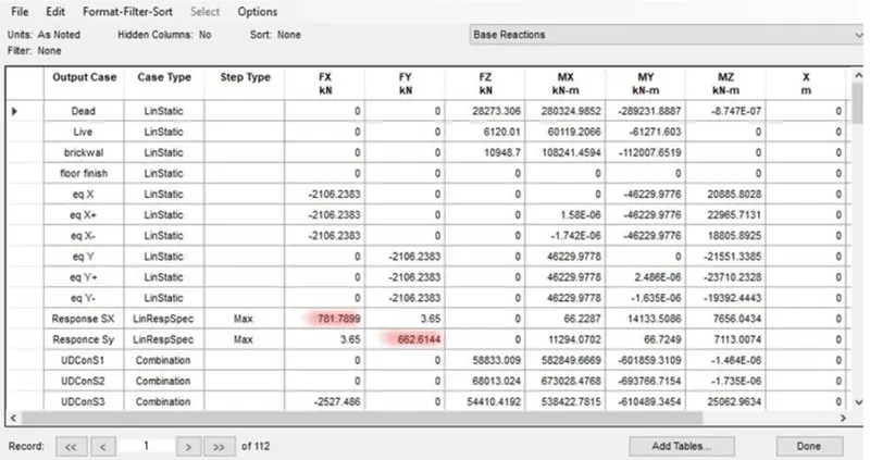
Correcting the response spectrum in X & Y directions by correcting the scale factor.
In X = (2110/780) X9806.65 = 26528.25
In Y = (2110/660) X9806.65 = 31351.56
Base reactions after correcting the scale factor is shown below.
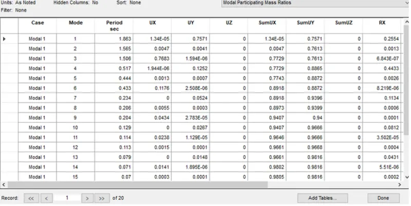
Step17: Model participating ratios are:
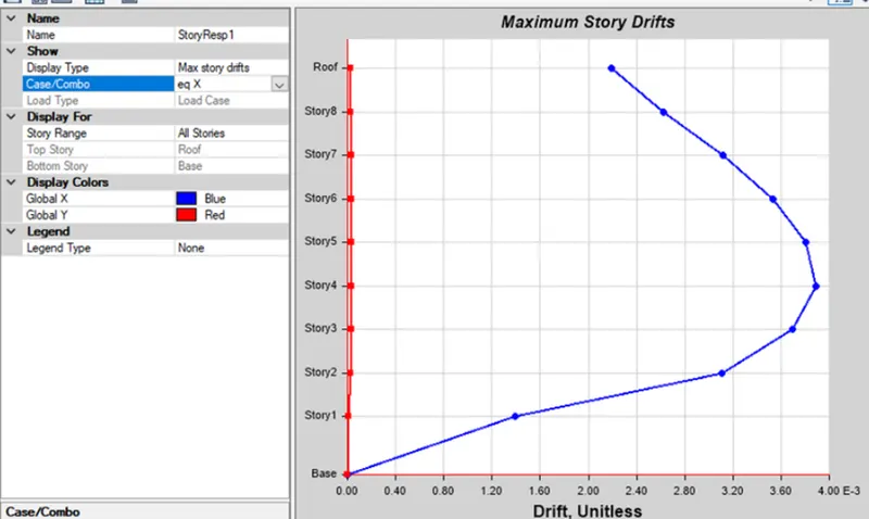
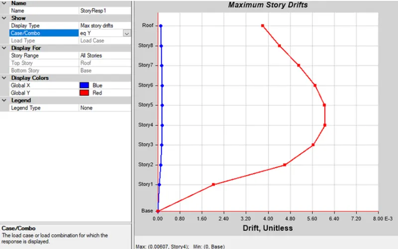
Step18: Maximum Drift in EQX and EQY directions.
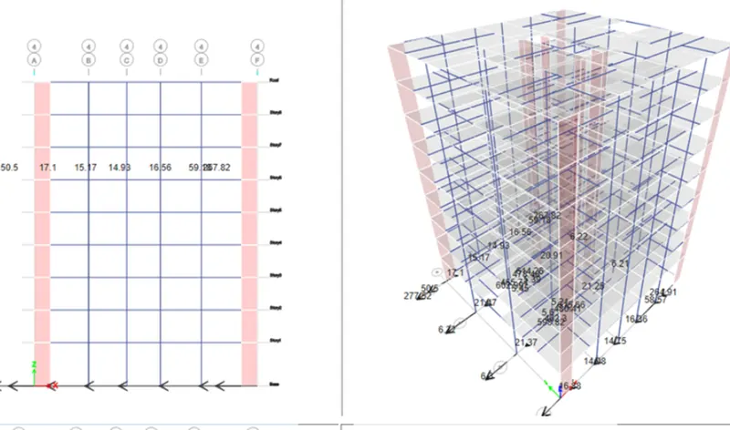
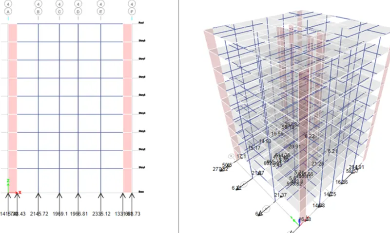
Step19: Checking the horizontal and vertical loads
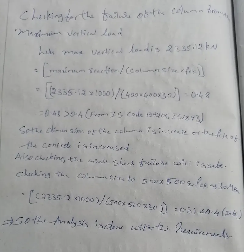
RESULT: Thus, as required the structural framing plan and ETABS modeling is done with seismic force assignment. And also ETABS model is analyzed and checked for failures.