Structural Modelling using Etabs 2018
Aim: To model and analyze the G+7 residential building from the given architectural drawings using the ETABS
Introduction:
- ETABS is an engineering software product that caters to multi-story building analysis and design.
- Modeling tools and templates, code-based load prescriptions, analysis methods and solution techniques, all coordinate with the grid-like geometry unique to this class of structure.
- Basic or advanced systems under static or dynamic conditions may be evaluated using ETABS
- ETABS modeling is the generalization that multi-story buildings typically consist of identical or similar floor plans that repeat in the vertical direction.
Step 1:
- First we have to open the etabs software.
- Next click on the file option at the left side top corner and select the new model
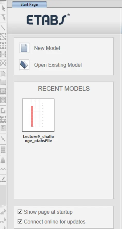
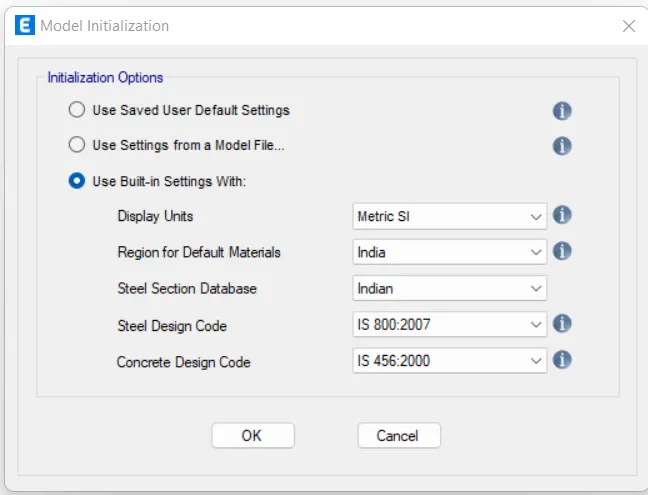
- After selecting the new model the new tab opens, in that tab we have to select 'Use Built-in Settings with' option
- After setting the model Initialization the templates tab will opens and, select the Grid only and press ok.
- Next we need to do the settings in Grid system data
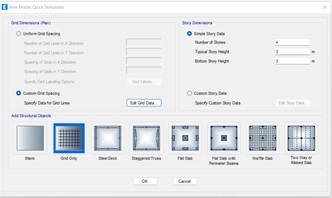
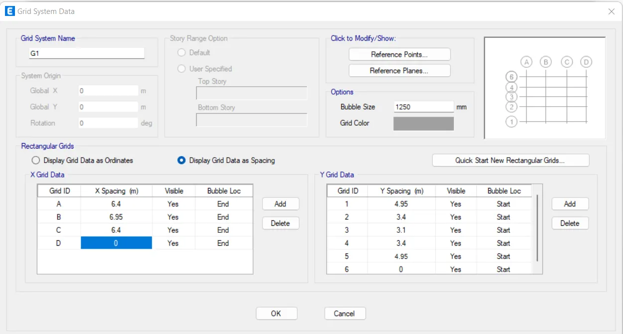
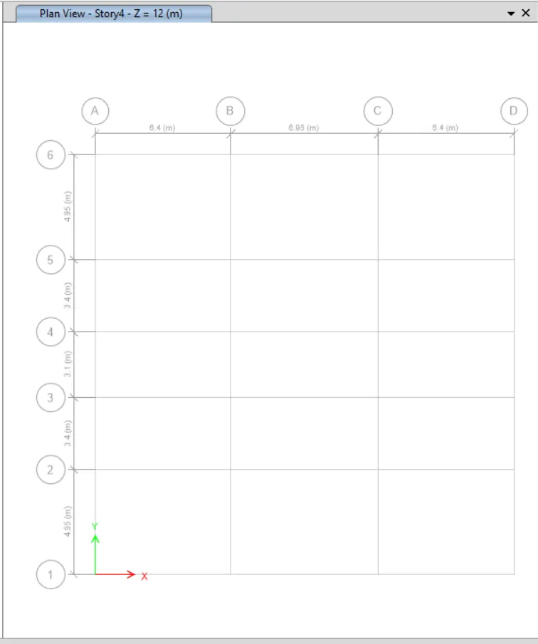
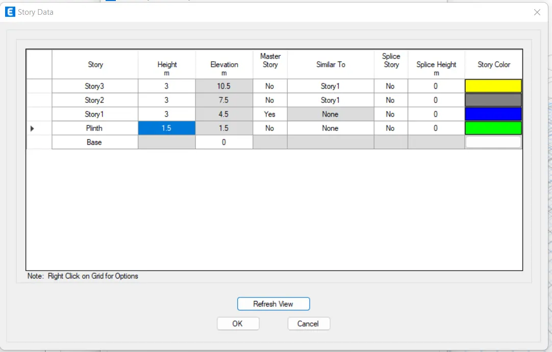
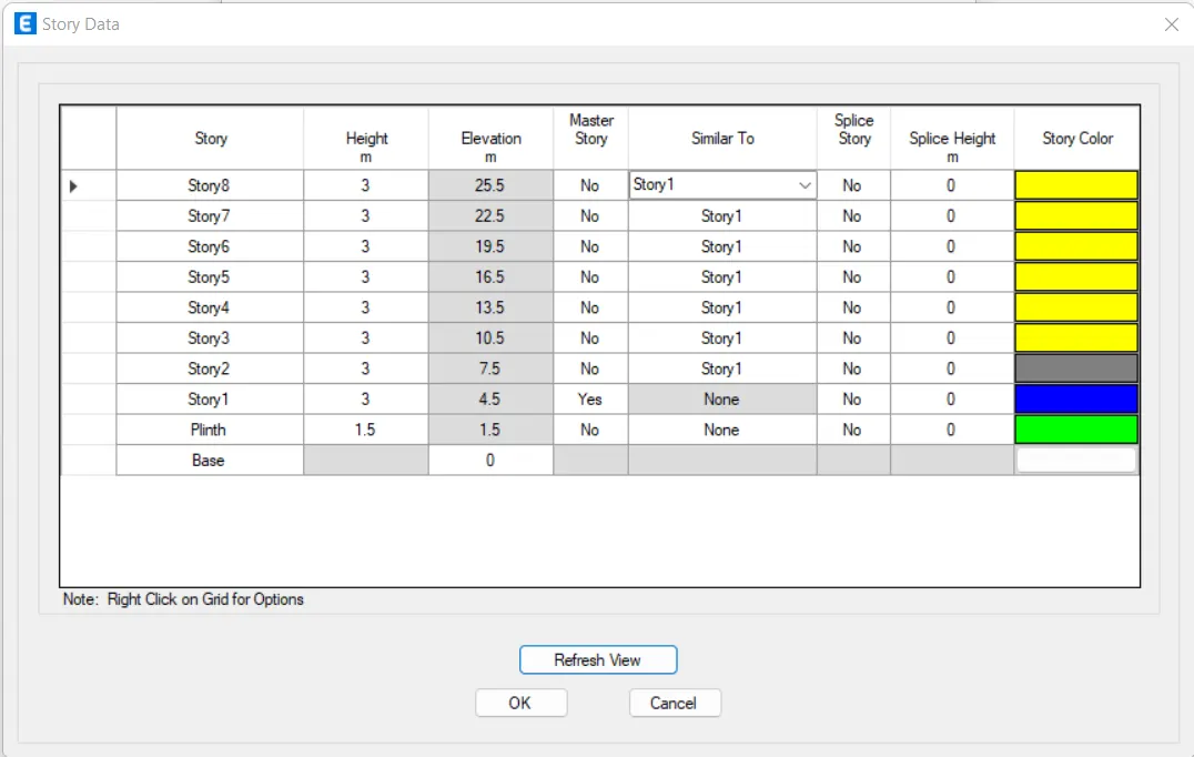
- Next we need to add the stories upto 7 story in the Story Data
- The 7 stories are added in the Story Data
Step 2:
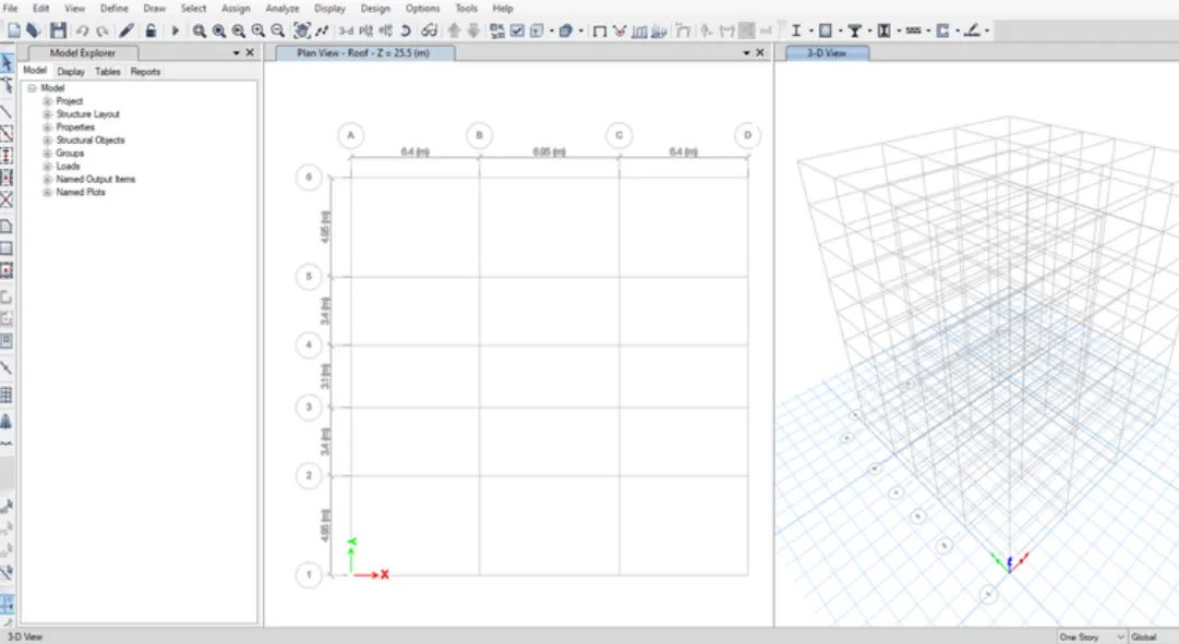
- Next the plan views are visible in the etabs screen
- Next we need to open the 3d-view, as shown in the below figure.
Step 3:
- Next we need to define option and select material properties
- After selecting the material properties the new tab appears, then we add new materials by selecting the Add new material option
Step 4:
- Now we need to add material type as concrete and grade as M25
- Next we need to check the material property data
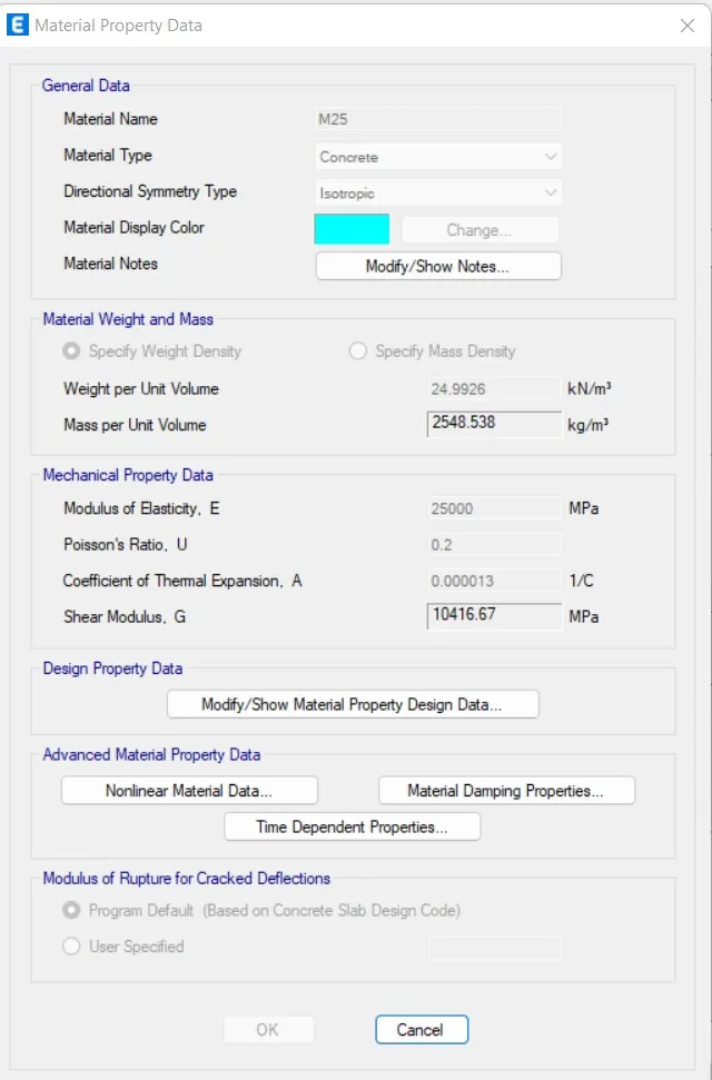
Step 5:
- Now we need to add new material type as rebar and grade as HYSD Grade 415.
- Next we need to check the material property data
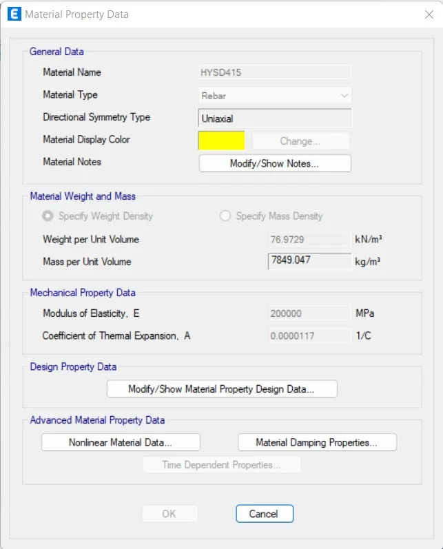
Step 6:
- Now we need to add new material type as rebar and grade as HYSD Grade 500.
- Next we need to check the material property data.
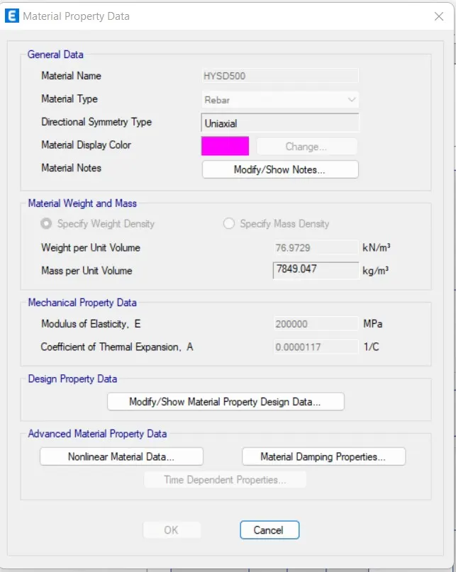
Step 7:
- Now we need to select the section properties and click on the frame sections
Step 8:
- After selecting the frame sections the new tab will be visible, in that we need to select the Add New Property
- After selecting the Add New Property, the new tab appears.
- In that new tab we select the Rectangular shape type in concrete
- Next the frame section property data will be visible, In that we add beam size as B250x450, as shown below.
- Next we need to select the Modify/Show Rebar option
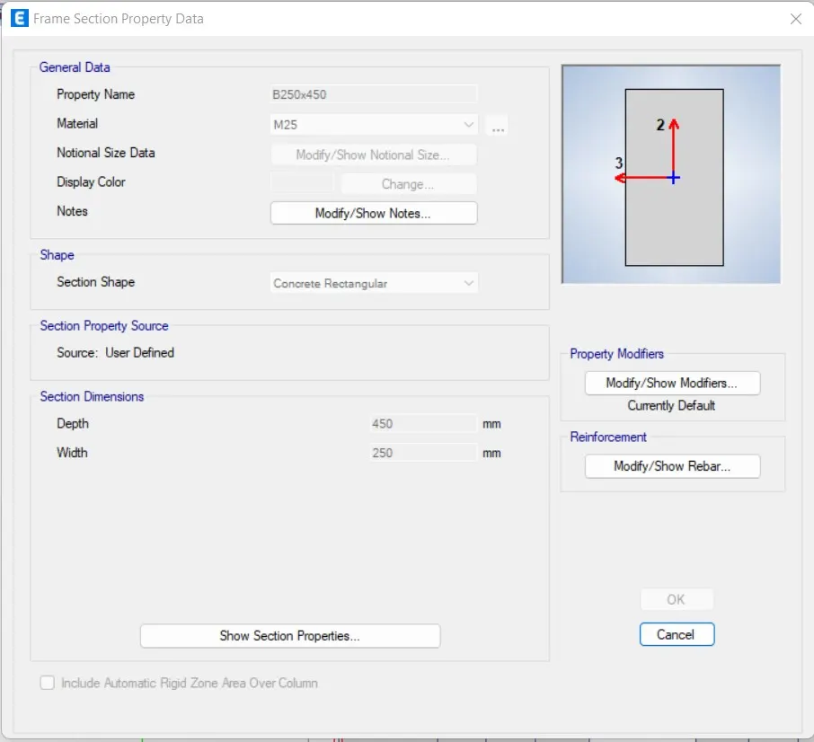
- After selecting the Modify/Show Rebar option the new tab appears, In that we select the design type as M3 Design only (Beam).
- Next we select longitudinal bars with the grade of HYSD500.
- Next we select Confinement bars with the grade of HYSD415.
- Again we have to select Rectangular shape type in concrete
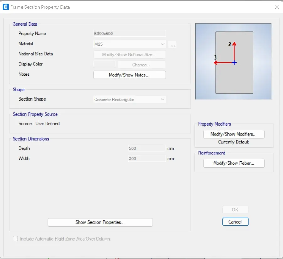
- Next the frame section property data will be visible, In that we add column size as B300x500
- Next we need to select the Modify/Show Rebar option
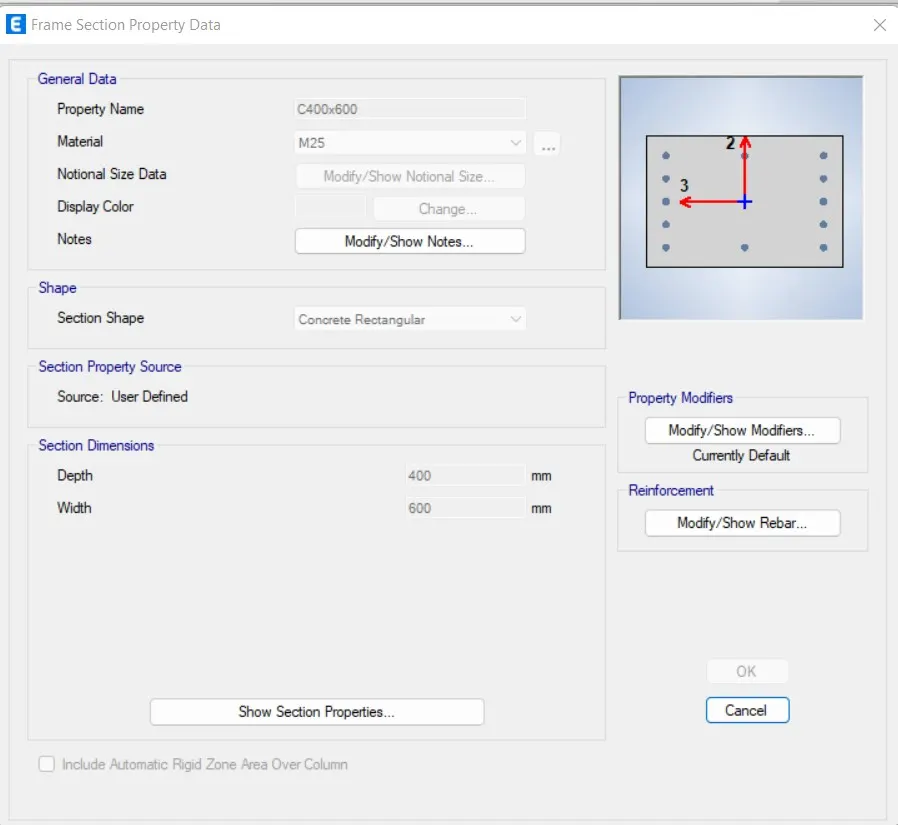
- Again we have to add the another column size as 400X600 in the frame section property data
Step 10:
- Next we select the slab section option from the section properties
- Next the slab properties tab will be vissible, In that we select the Modify/Show Property option
- After selecting the Modify/Show Property option, the new tab appears.
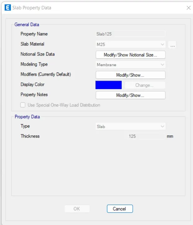
- In that we need to put the slab name as Slab 125, it means slab with the thickness of 125mm.
- And we take the concrete grade as M25
- Next we have to click the ok option.
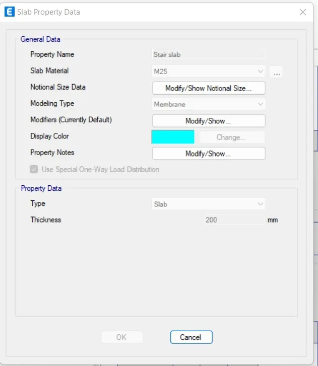
- Now we take the slab thickness separately for staircase with the thickness of 200mm
Step 12:
- Next we need to add the columns using the Quick draw columns option

Step 13:
- Next we need to add the beams using the Quick draw beams option
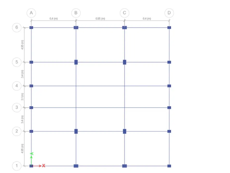
Step 14:
- Next we need to add the secondary beams using the Quick draw beams option
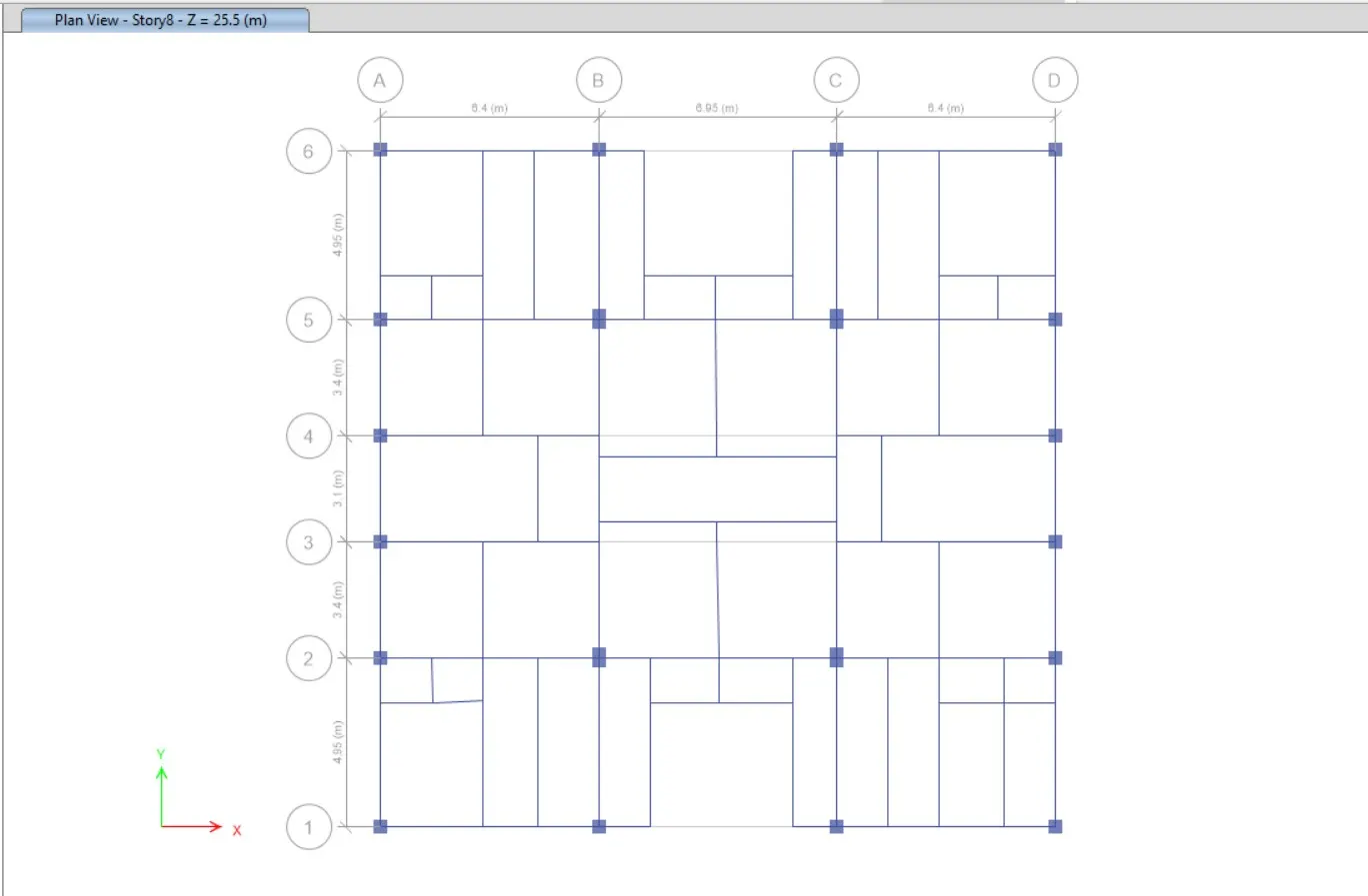
Step 15:
- Next we need to add the slabs using the Quick draw floor/wall option
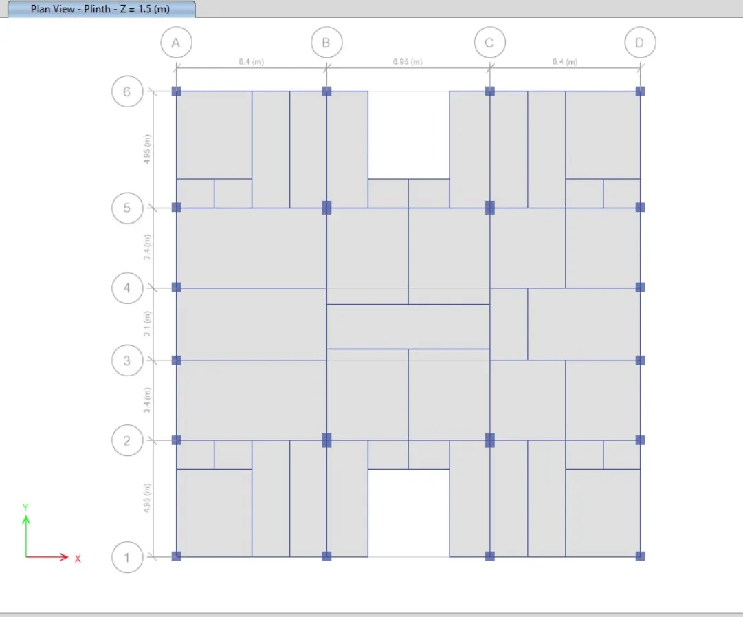
Step 16:
- Next we add the shear walls in required locations in the residential building
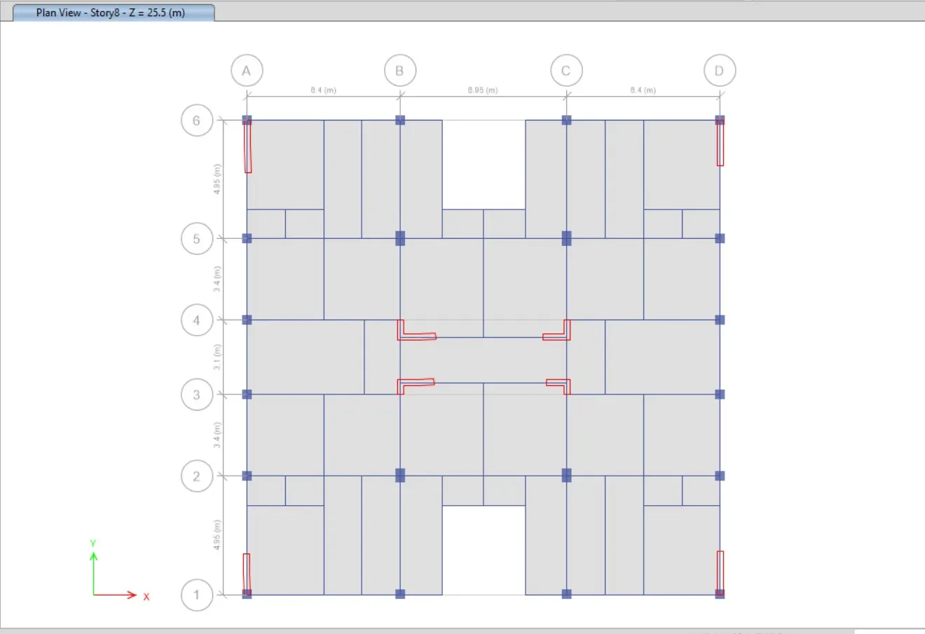
Step 17:
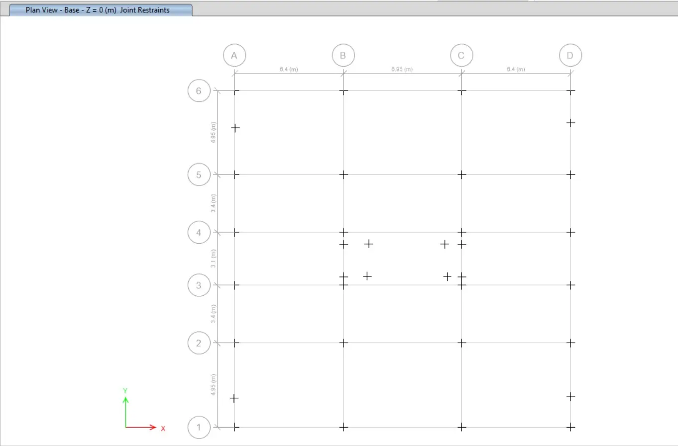
- Now we go to the base plan and select all base joints.
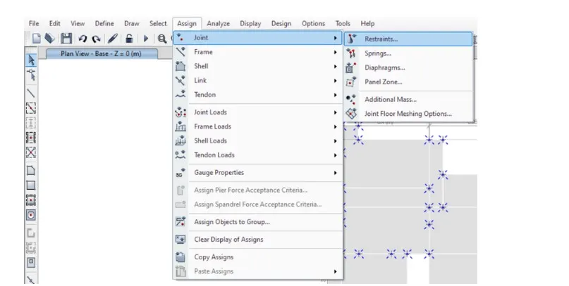
- Next we select the Restraints from joint option, as shown below.
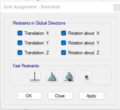
- Now we need to select the fixed joint and click on apply and then click on close button, as shown below.
Step 18:
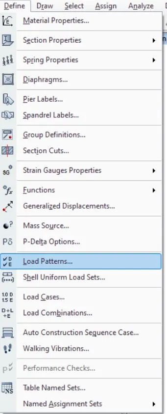
- Next we need to select the load patterns from the define option
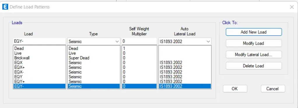
- Now we should add Dead load, live load, Brickwall load, and earthquake load.
Step 19:
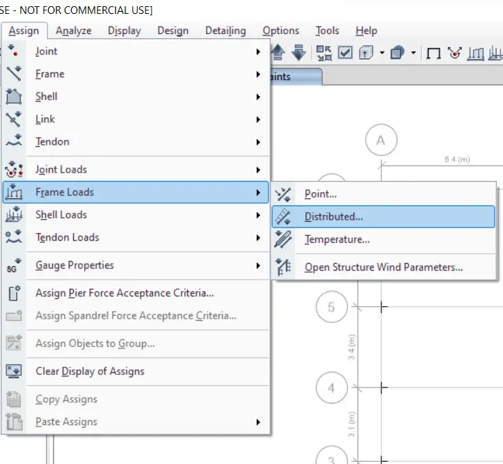
- Next we need to select the distributed load from the frame loads
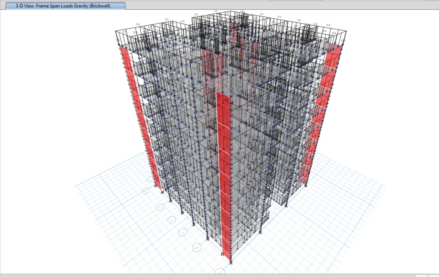
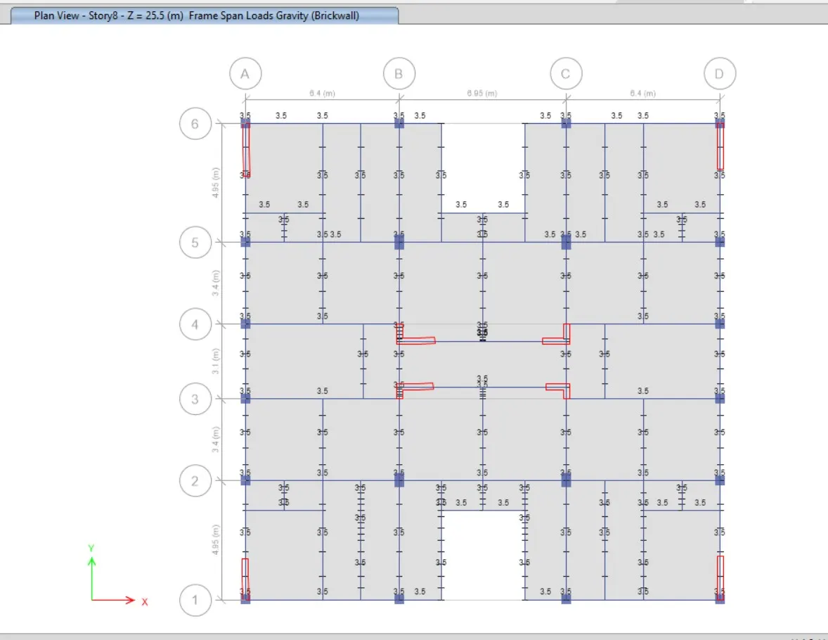
- Then after the new tab will appear, In that we select load pattern as Brickwall, and we take uniform load as 3.5 kN/m and then click on the apply button and close.
Step 20:
- Next we have to click on the assign option and then select shell loads, from the shell loads we select the Uniform option
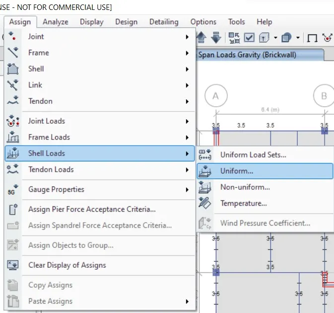
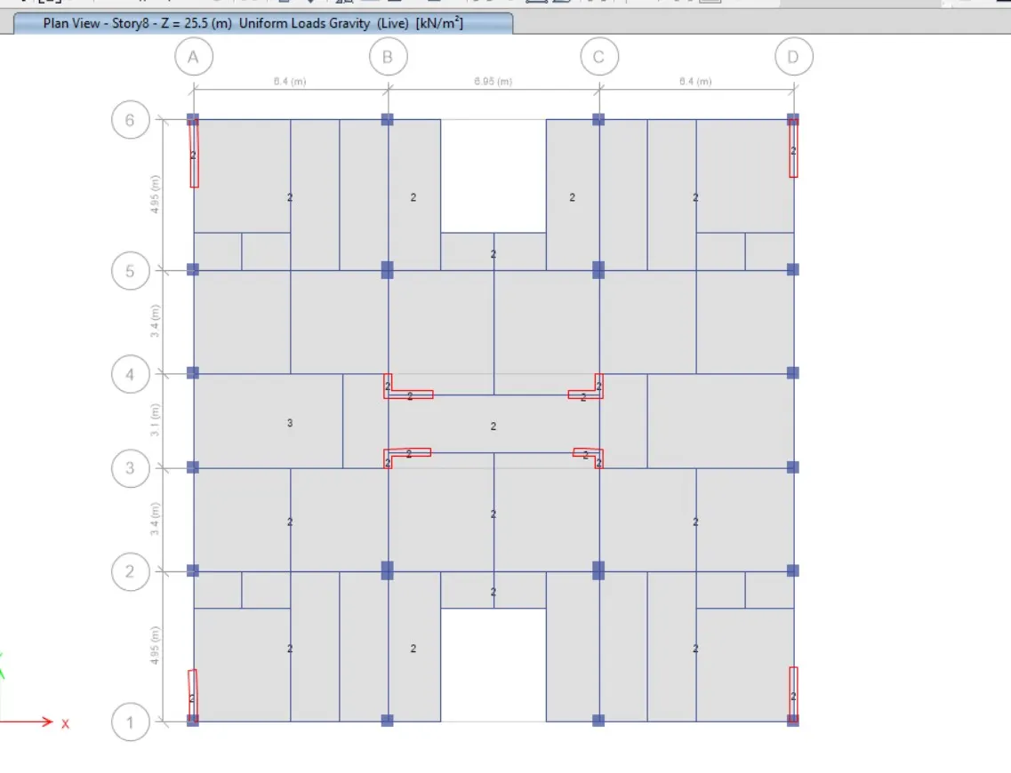
- Here we apply the 3kN/m2 live load for the staircase portion, lift core area.
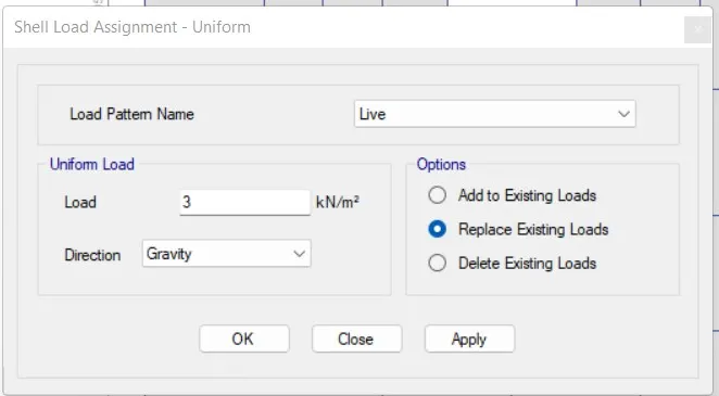
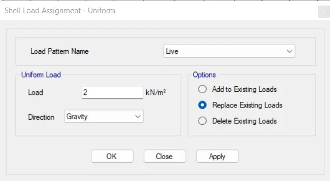
- Next we apply the 2kN/m2 live load for the remaining portions in the residential building
Step 21:
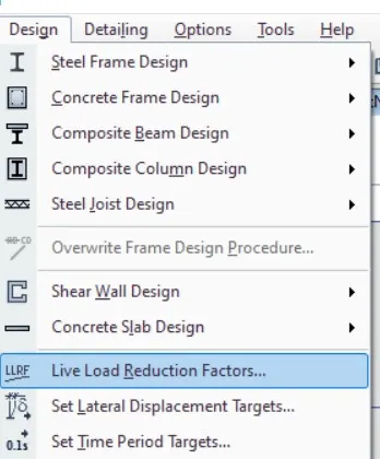
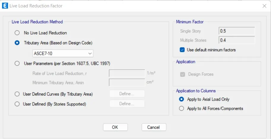
- Next we have to select live load reduction factors from the design option
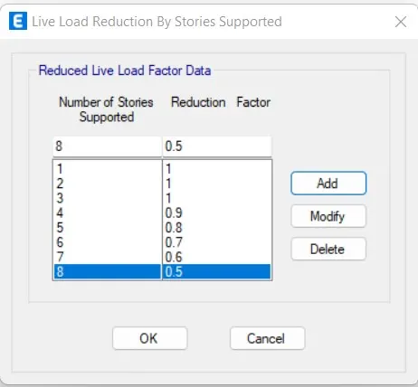
- Now we add the reduction factor by decreasing 10% from 1st floor to last
Step 22:
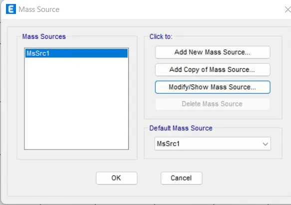
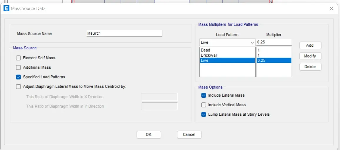
- Next, from the define option we select the mass source
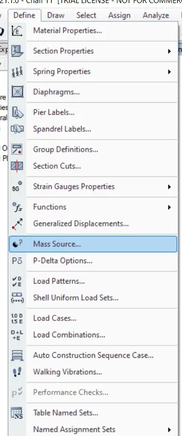
- Next we add the load patterns in the Mass Source Data
Step 23:
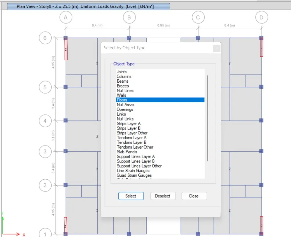
- In the select option we select object type option
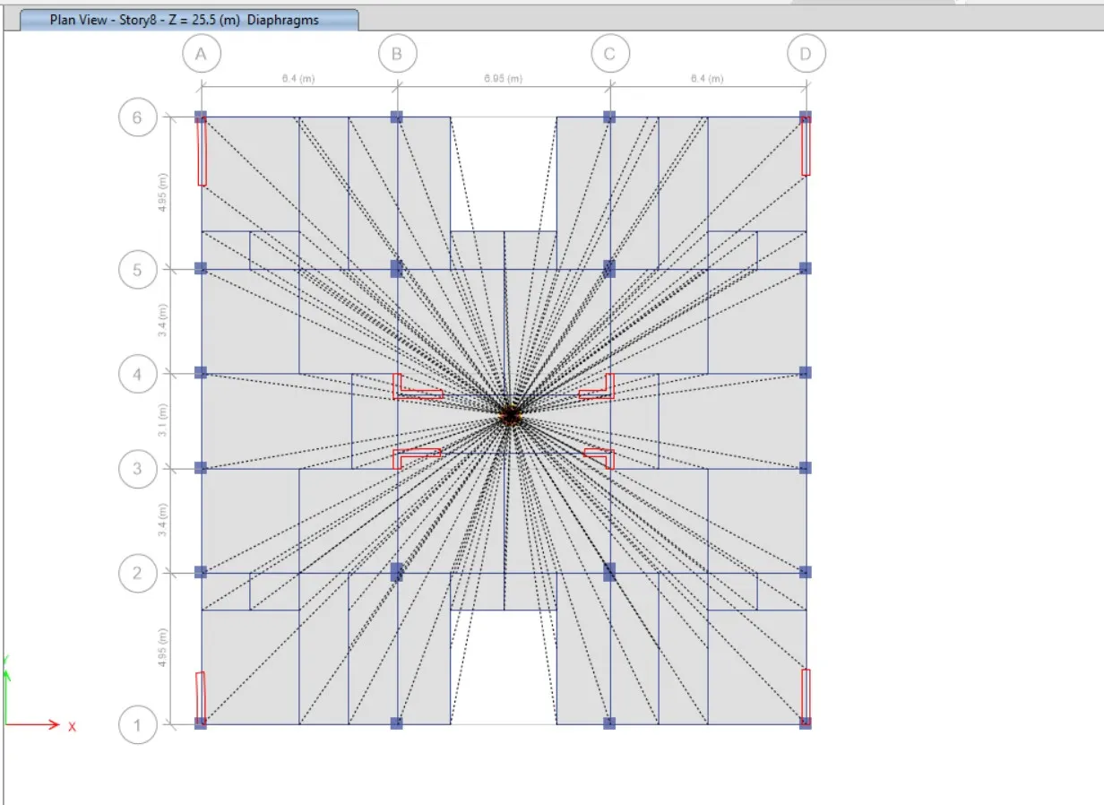
- After selecting the object type option, the new tab will be visible, In that select the floors and click on the select button and close.
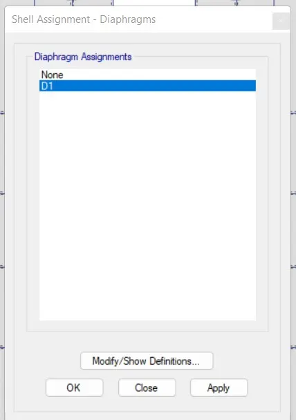
- Next we have to select the Diaphragms from the shell option
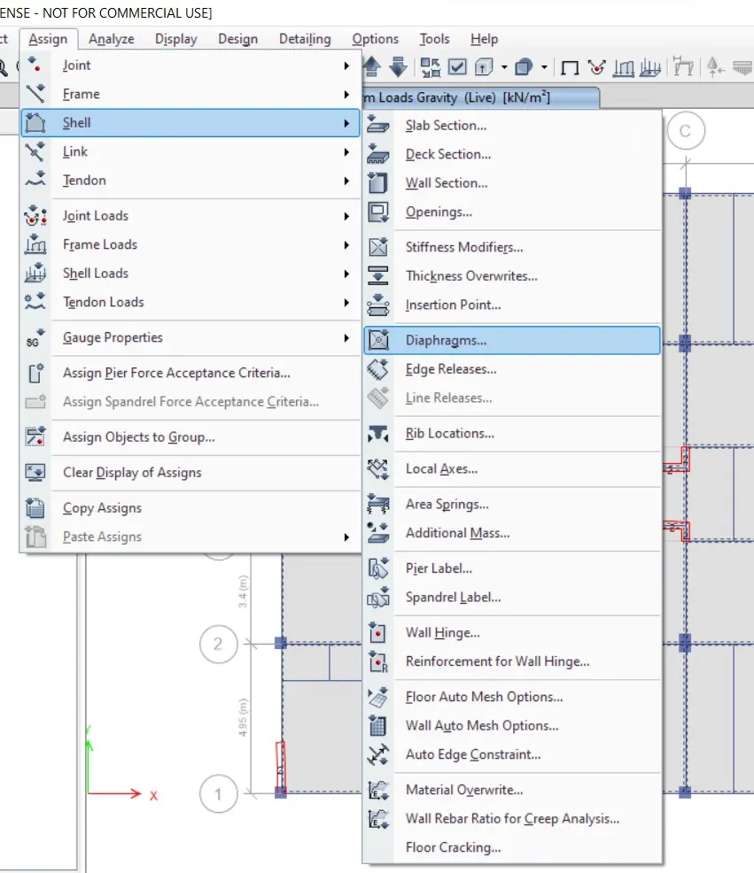
- After selecting the diaphragms the new tab will appear, in that select D1 and click on the apply button and close.
Step 24:
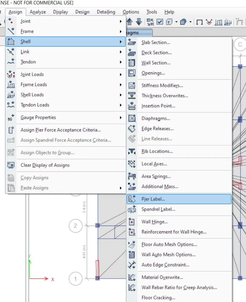
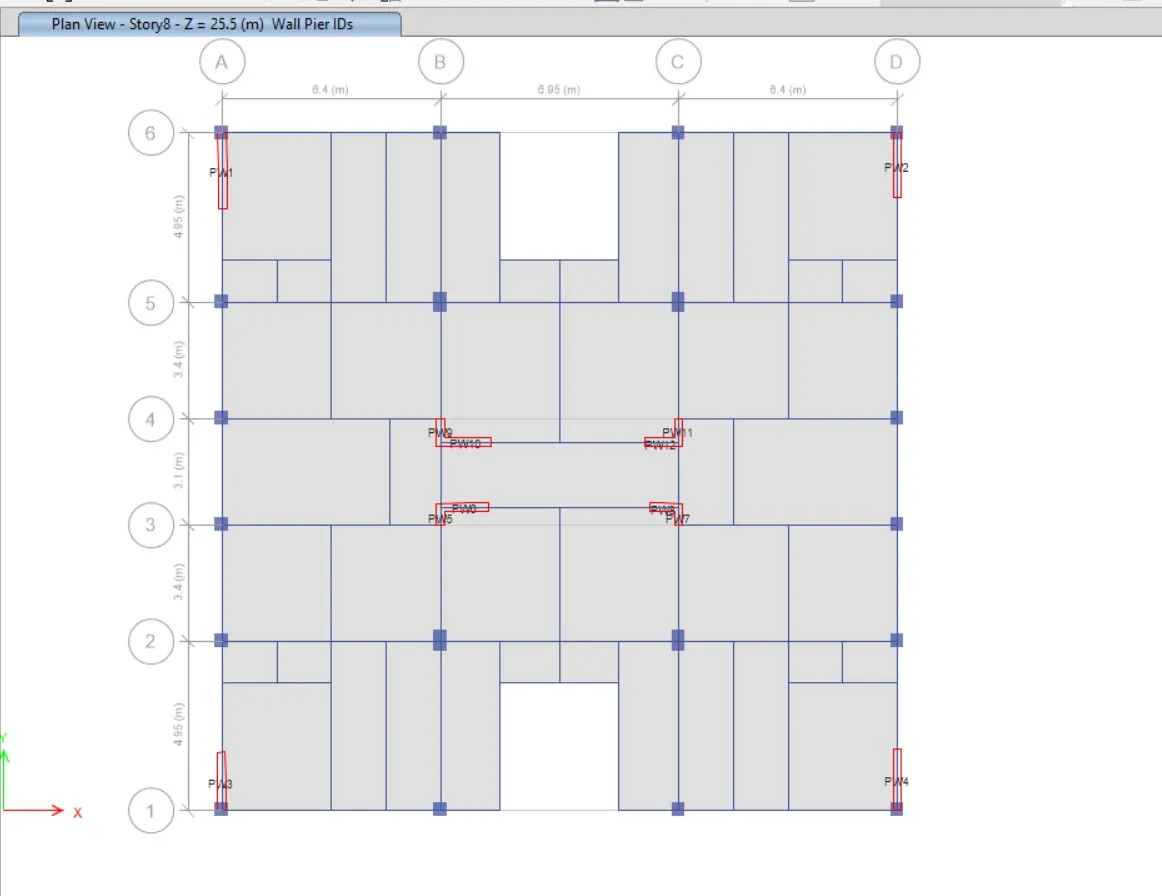
- Next we have to select the Pier label from the shell option
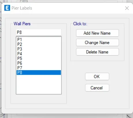
- Before going to the shear wall design we have to assign the names for the shear walls
Step 25:
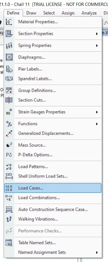
- Next, from the define option we select the load combinations
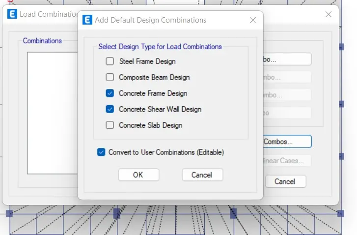
- After selecting the load combinations the new tab is visible, In that we select 'Add Default Design Combos' option.
- Next we select "concrete frame design" & "concrete shear wall design" in the 'Add Default Design Combinations'
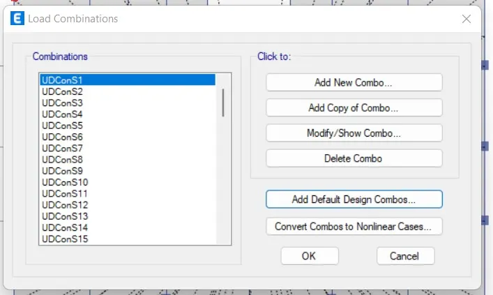
- Now we can see here that the load combinations are visible
Step 26:
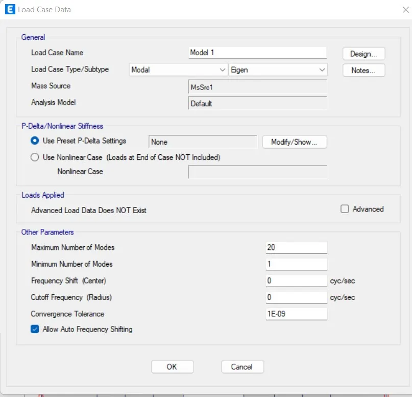
- Next we select the Modal cases from the Define option
- After selecting the Modal cases the new tab is visible, In that we give modal case name as Modal 1 & we give the maximum number of modes as 20
Step 27:
- Next we have to check the model by clicking the check model option
- After the model is checked, then the warning tab will be visible and it tells that there is no warning messages
Step 28:
- Now we select the Response spectrum from the Functions from define option
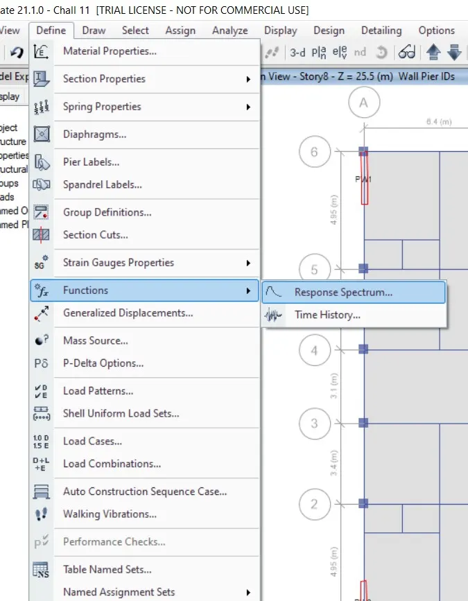
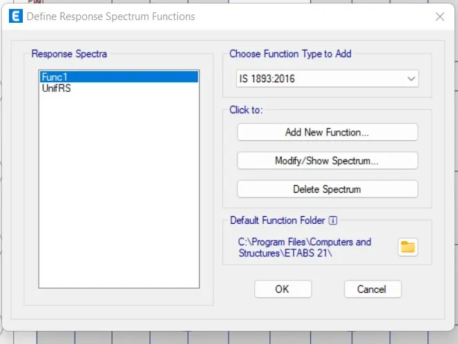
- After selecting the Respnse spectrum the new tab is visible, In that we choose IS 1893 2016 from the 'Choose function type' and click on the Modify/Show spectrum option, as shown below.
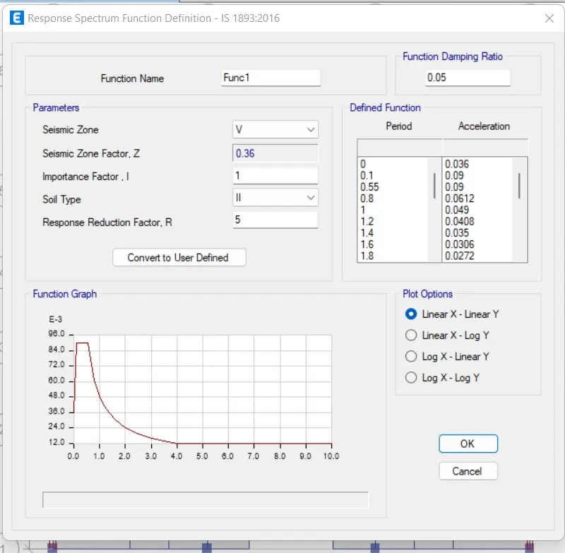
- After selecting the modify/show spectrum option the new tab will be visible, In that we give the Function name as 'IS FUNCTION' and remaining details will be set by the software itself,we don't need to change any of the details in that response spectrum function tab
Step 29:
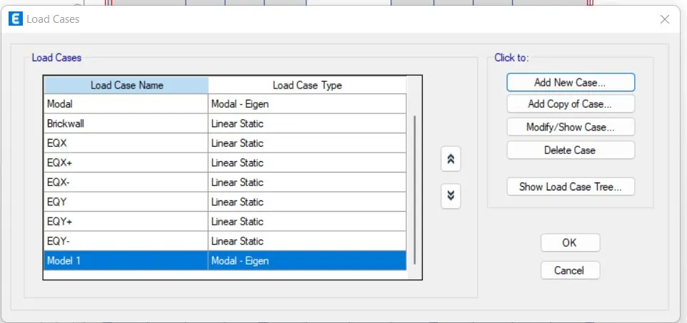
- Next we have to select the Load cases from the Define option
- Next the Load cases tab will be visible, In that we select the 'Add new case'
- Now we have to enter the details of load case in the 'Load case data'
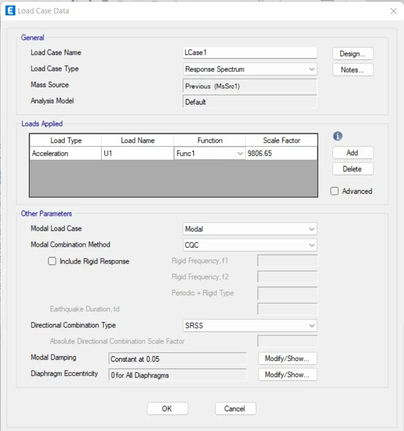
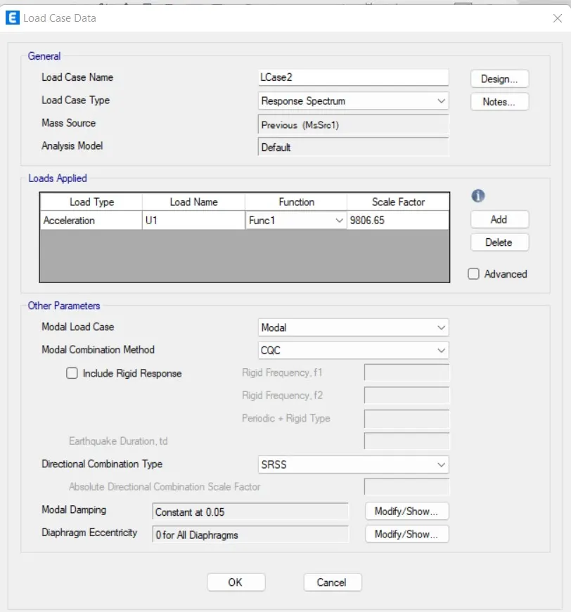
- Now we have to do the run analysis
Step 30:
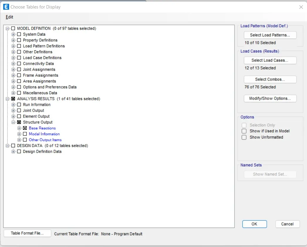
- Next, from the display option we select the show tables option
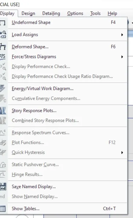
- After selecting the show tables option the new tab will be visible.
- Now we select the Base Reactions and click on the ok button
- We put the above values as scale factor for response spectrum at X and Y directions in the load case data.
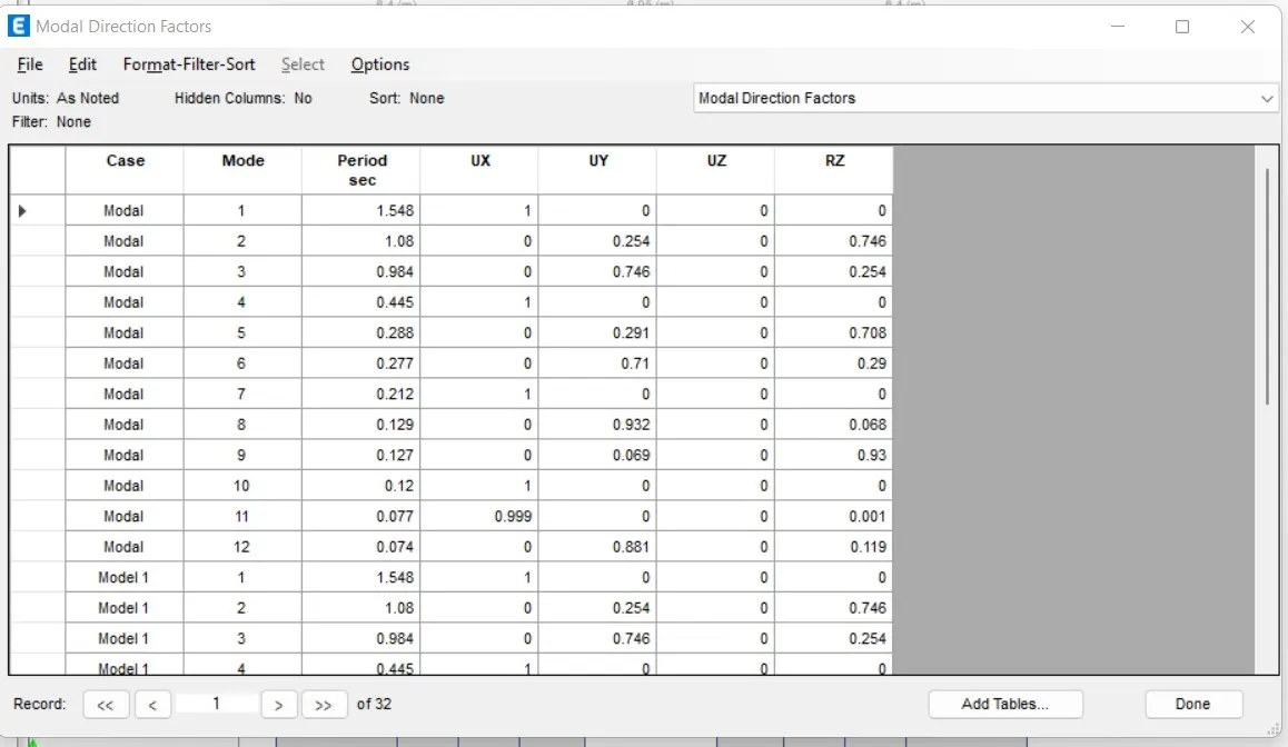
- After these values for response spectrum as scale factors at X and Y directions in load case data
Step 31:
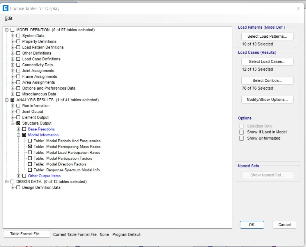
- Next, from the display option we select the show tables option
- After selecting the show tables option the new tab will be visible.
- Now we select the Modal Participating Mass Ratios and click on the ok button
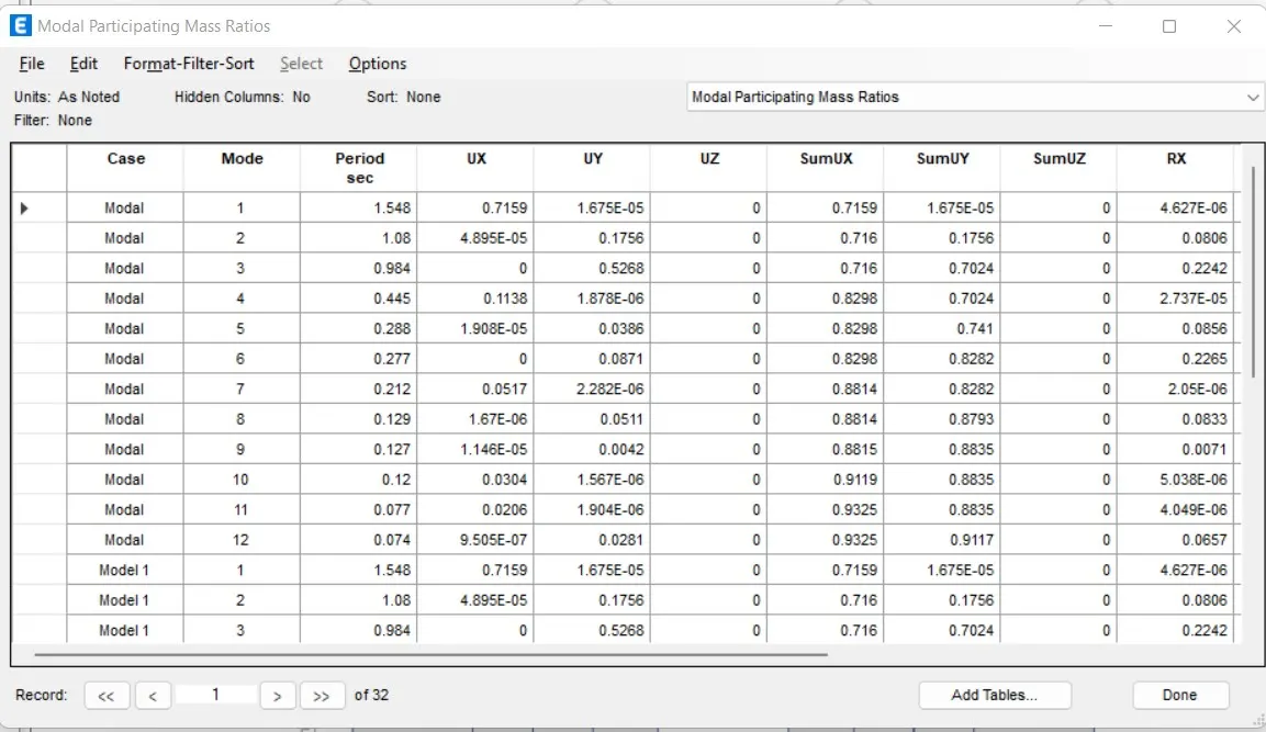
- Now the Modal Participating Mass Ratios table will be visible
Step 32:
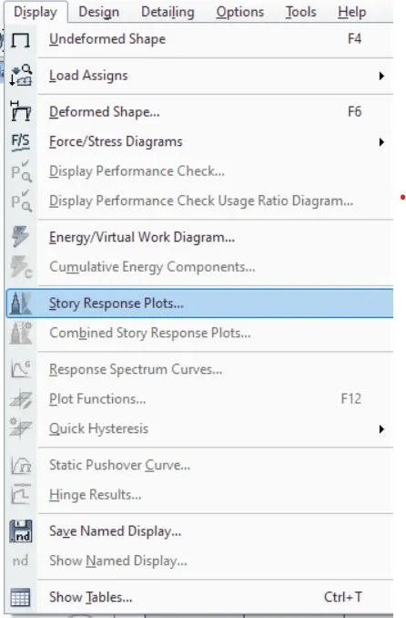
- Next we select the Story response plots from the Display option
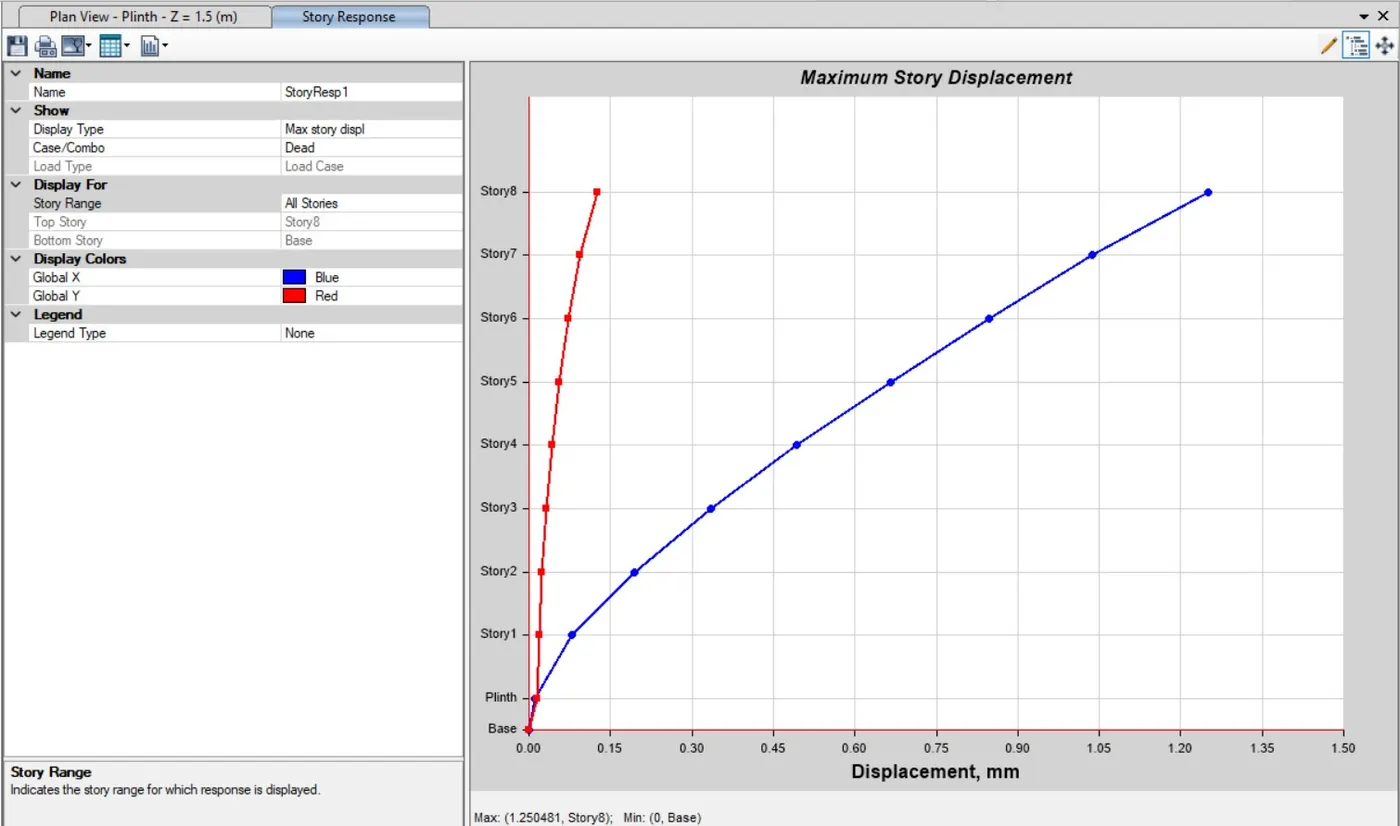
- The story response for maximum story drifts
Step 33:
- Next we open the select plan view tab and select the base floor
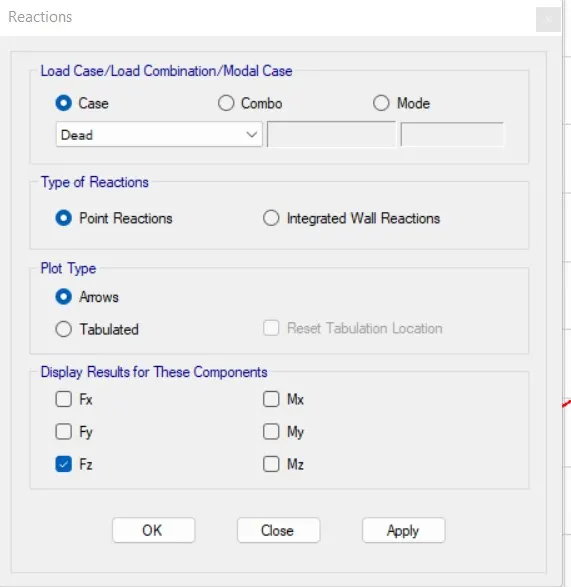
- Next we have to open the reactions tab, then we select the eartquake load towards X-direction(EQX) in the load case, then click on the ok buttion
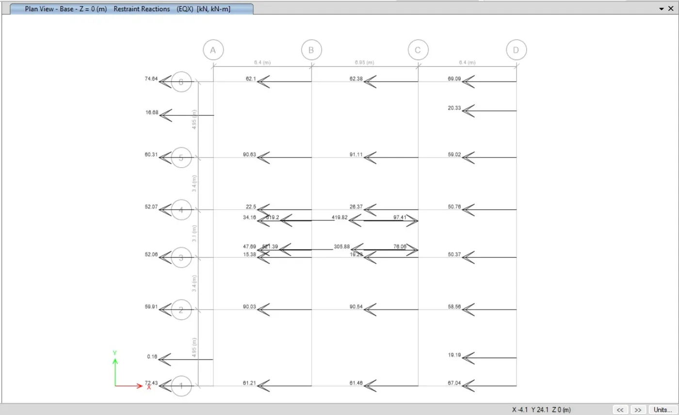
- Now the base shear reactions will appear
- When we divide the base shear taken up by the shear wall divided by the total base shear of building will get the % of the shear forces taken up by the shear wall.
- And if that is less than 80%, then the more shear walls we need to add to the structure.
Result :
- In order to find the % value for the load capacity of the shear wall which is taken by shear wall with the base shear of the building,if the number of the % is 80%, there is no need to provide more shear walls.But if the percentage is less than 80% then we have to provide more shear wall in our structure.
- Finally the The G+7 residential building model has been analysed successfully.
******************