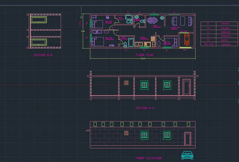
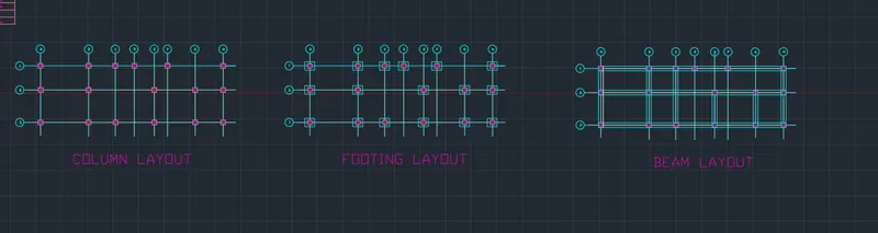
Project 1 _Creating an Architectural plan for the provided plot size and develop relevant basic structural drawings
Aim:
1. To draw the architectural drawing of a residential building
- Floor Plan
- Elevation
- Section
2. Structural drawing of a residential building
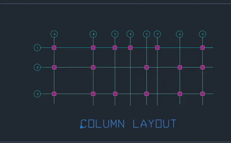
- Column Layout
- Footing Layout
- Beam Layout
Introduction:
The buildings are planned based on the site plan. The structural drawing is about to give the detailed layout of foundation, columns and beams. The proposed residential plan comes under EAST Facing and size for about 18.3mx6m.
Commands used :
- Limits
- Units
- Extend
- Circle
- Layer
- X-line
- Line
- Offset
- Fillet
- Hatch
- DIMLINEAR
- Text
- Design center
- Trim
Procedure :
1.Architectural drawing :
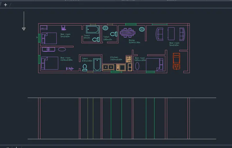
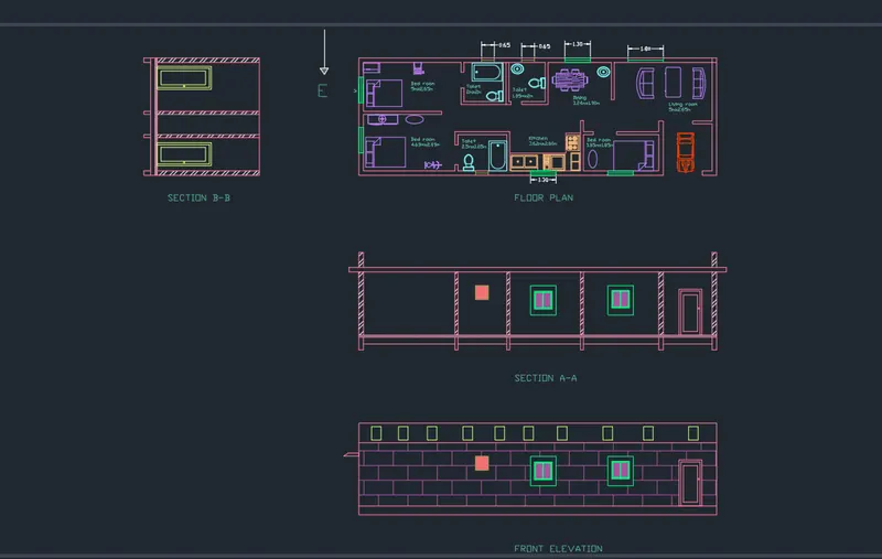
a. Floor Plan
Step 1 :
- Open the Autocad file and set as metric units
- Command - Startup
- Command - D to change the settings into Decimal units
- Command - UN to change the unit settings, by clicking it and select the decimal units and precision to zero
- Command - LIMITS,set the limits as per the required
- Command - Zoom and select all
Step 2 :
- Command - Line
- Specify the 1st point and draw a line along y aixs for about 6m
- Specify the next point and draw a line along x aixs for about 18.3m
- Specify the next point and draw a line along y aixs for about 6m downwards
- Select close option and form a rectangle

Step 3 :
- Command - Offset
- Specify the 1st point and select the through option and object and specify the offset distance for about 0.23m of wall thickness.
- Repeat the same process and form the offset distance for all the four sides wall thickness
- The main entrance is in east direction
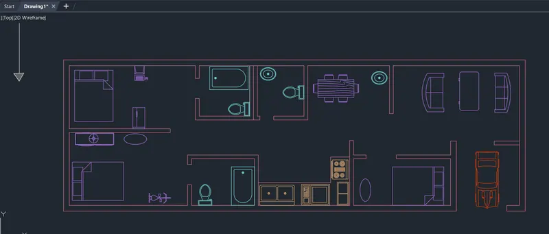
- specify the offset distance for all the rooms for the layout.
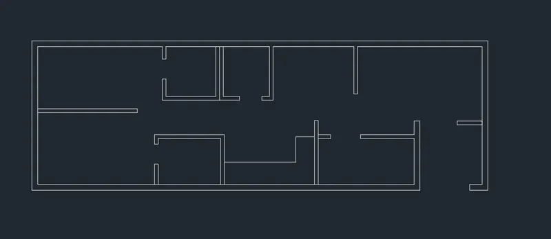

Step 4 :
- Command - DC (design centre)
- Select to add the components for the layout, pick and place it wherever required
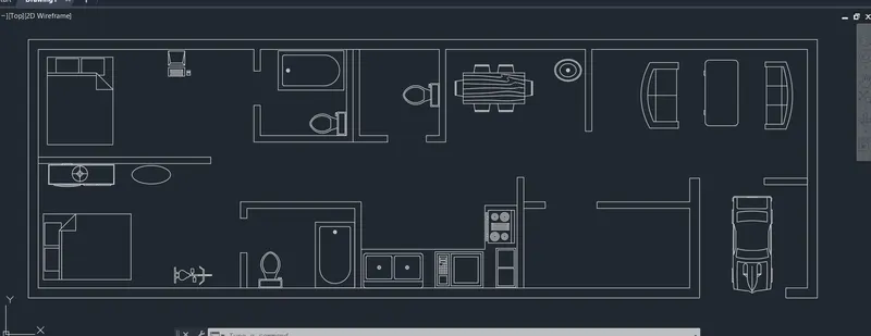
Step 5 :
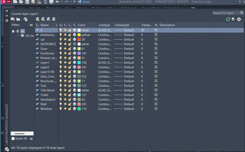
- FRom the Toolbar select The layer properties and create a new layer for all the objects in the layout
Step 6 :
- Command - Line
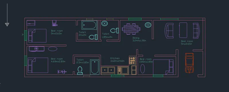
- SPecify the 1st point and draw the windows for the required plan
- Command - TEXT
- Specify the 1st point and enter the height of the text and rotation angle as 0 and enter the text to name the rooms for the plan.
Step 7 :
- Command - Line
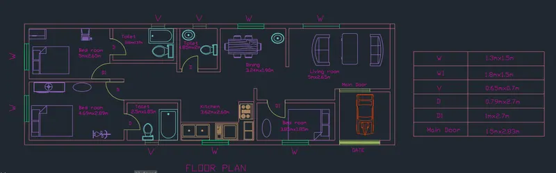
- Specify the 1st point and draw the line for the doors required
- Command - Circle
- SPecify the 1st point of circle and draw circle of radius to form a door
- Command - Trim
- Select the object and trim the unwanted lines
b. Elevations :
Step 1 :
- Command - Xline
- Project the lines from the floor plan
- Draw a horizontal line to represent the ground surface and top level
- Command - Trim
- Select the object and trim the unwanted lines
Step 2 :
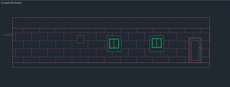
- Command - Offset
- Select the through option and object and specify the offset distance
- Offset distance of 0.45m from ground level to form the plinth level
- Offset distance of 0.30m from plinth level to form the height of the residential building
- Offset distance of 0.75m to form the parapet
- using the dc command insert the door for an height of 2.83m and also draw the door and window using the dimensions
- Command - Hatch
- Select the object ( wall of the building ) and select the code from the hatch command as BRICK
Step 3 :
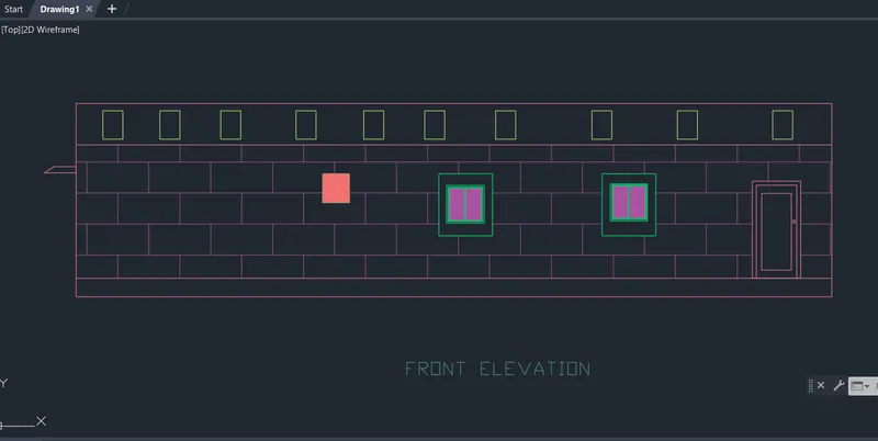
- Command - Hatch
- Select the object ( windows and ventilation) and select the code from the hatch command as solid and differentiate the colors
c. Sections :
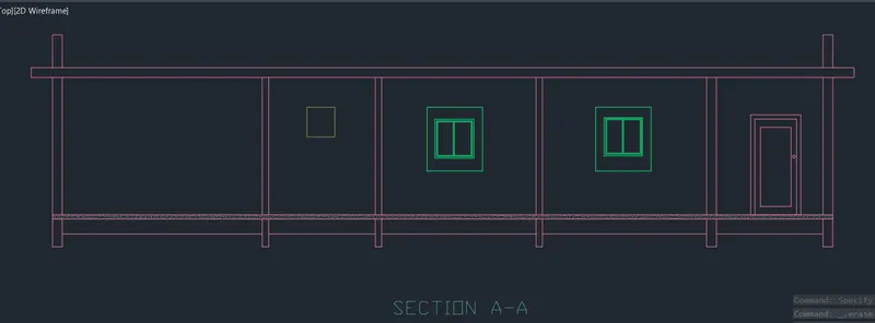
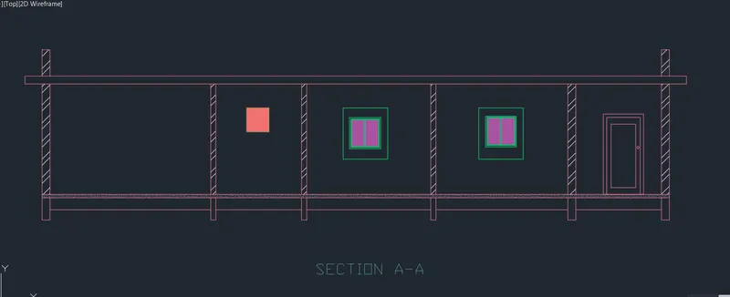
1. Section A-A
Step 1 :
- Command - Xline
- Project the lines from the floor plan
- Draw a horizontal line to represent the ground surface and top level
- Command - Trim
- Select the object and trim the unwanted lines
- Command - Offset
- Select the through option and object and specify the offset distance
- Offset distance of 0.45m from ground level to form the plinth level
- Offset distance of 0.30m from plinth level to form the height of the residential building
- Offset distance of 0.75m to form the parapet
- using the dc command insert the door for an height of 2.83m and also draw the door and window using the dimensions
Step 2 :
- Command - Hatch
- Select the object ( Wall, windows and ventilation) and select the code from the hatch command as solid & ANSI32 and differentiate it by the colors
2. Section B-B
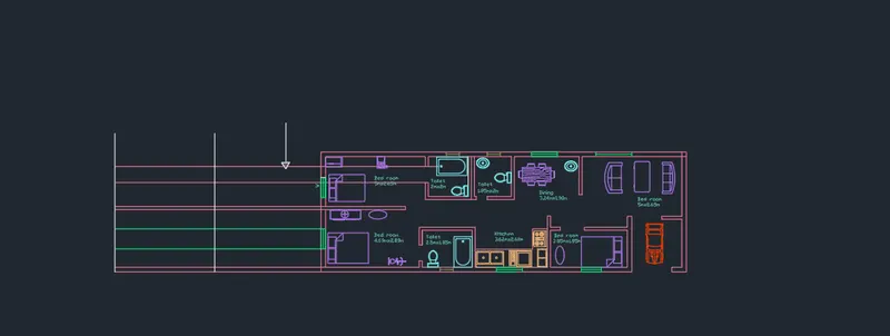
Step 1 :
- Command - Xline
- Project the lines from the floor plan
- Draw a horizontal line to represent the ground surface and top level
Step 2 :
- Command - Trim
- Select the object and trim the unwanted lines
- Command - Offset
- Select the through option and object and specify the offset distance
- Offset distance of 0.45m from ground level to form the plinth level
- Offset distance of 0.30m from plinth level to form the height of the residential building
- using the dc command insert the door for an height of 2.70m
- Command - Hatch
- Select the object ( Wall) and select the code from the hatch command as ANSI32 and differentiate it by the colors
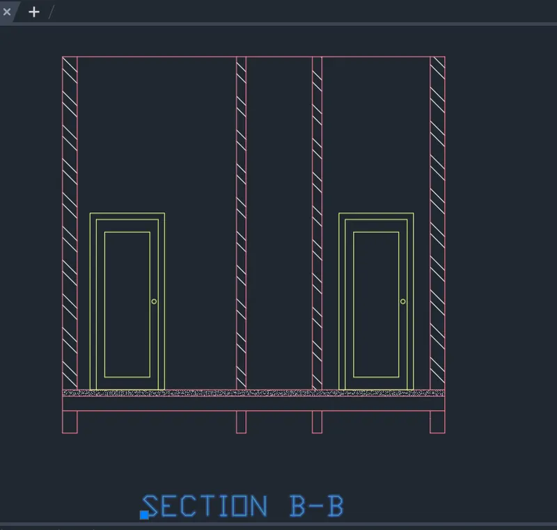
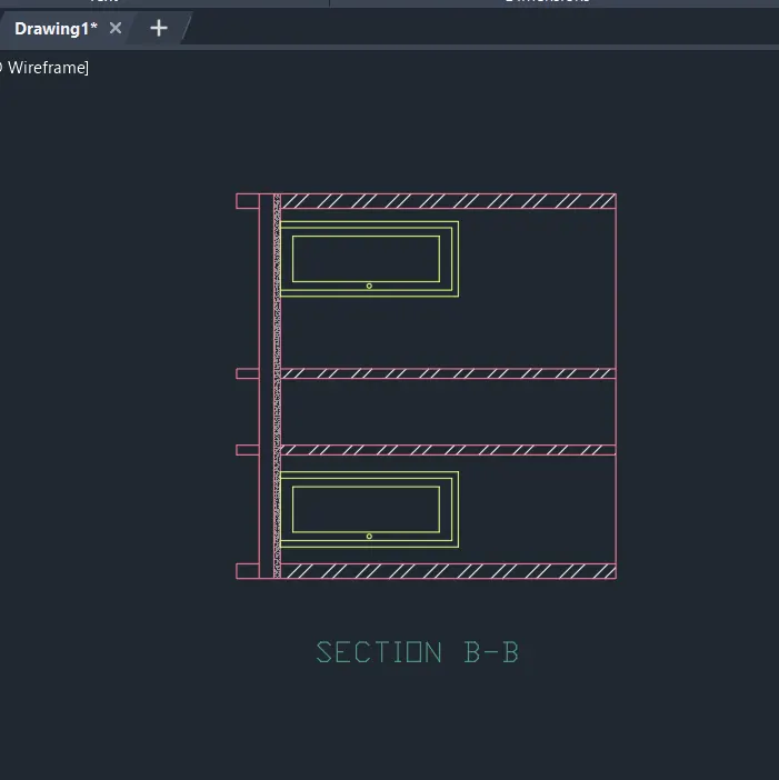
Final Result Of Plan, ELevations & Sections
2. Structural drawing of a residential building
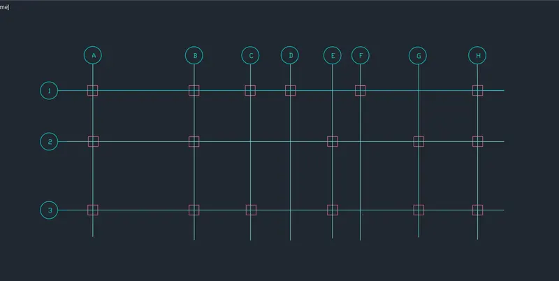
i) Column plan
Step 1 :
- Command - Line
- Draw the centre line from the wall and place the columns of dimensions intersections
- Erase the outer walls and mark the gridlines along x axis and y axis
Step 2 :
- Command - Hatch
- Select the object ( Column) and select the code from the hatch command as Solid and differentiate it by the colors
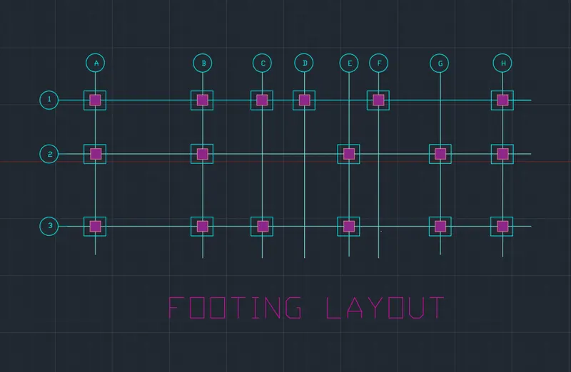
ii) Footing Layout:
- Footings are provided using the rectangle command based upon the Centre line drawing of the layout provided in the column
- Draw the rectangle of dimension
- Erase the outer walls and mark the gridlines along x axis and y axis
- Command - Hatch
- Select the object ( Footings) and select the code from the hatch command as Solid and differentiate it by the colors
iii) Beam Layout:
- Connect the columns with beams by the gridlines along x axis and y axis
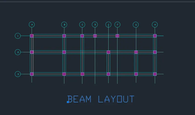
Result :
Architectural and structural drawings for the proposed residential building is completed